

Page 1
Ver. 1.1 – 4-19
Page1
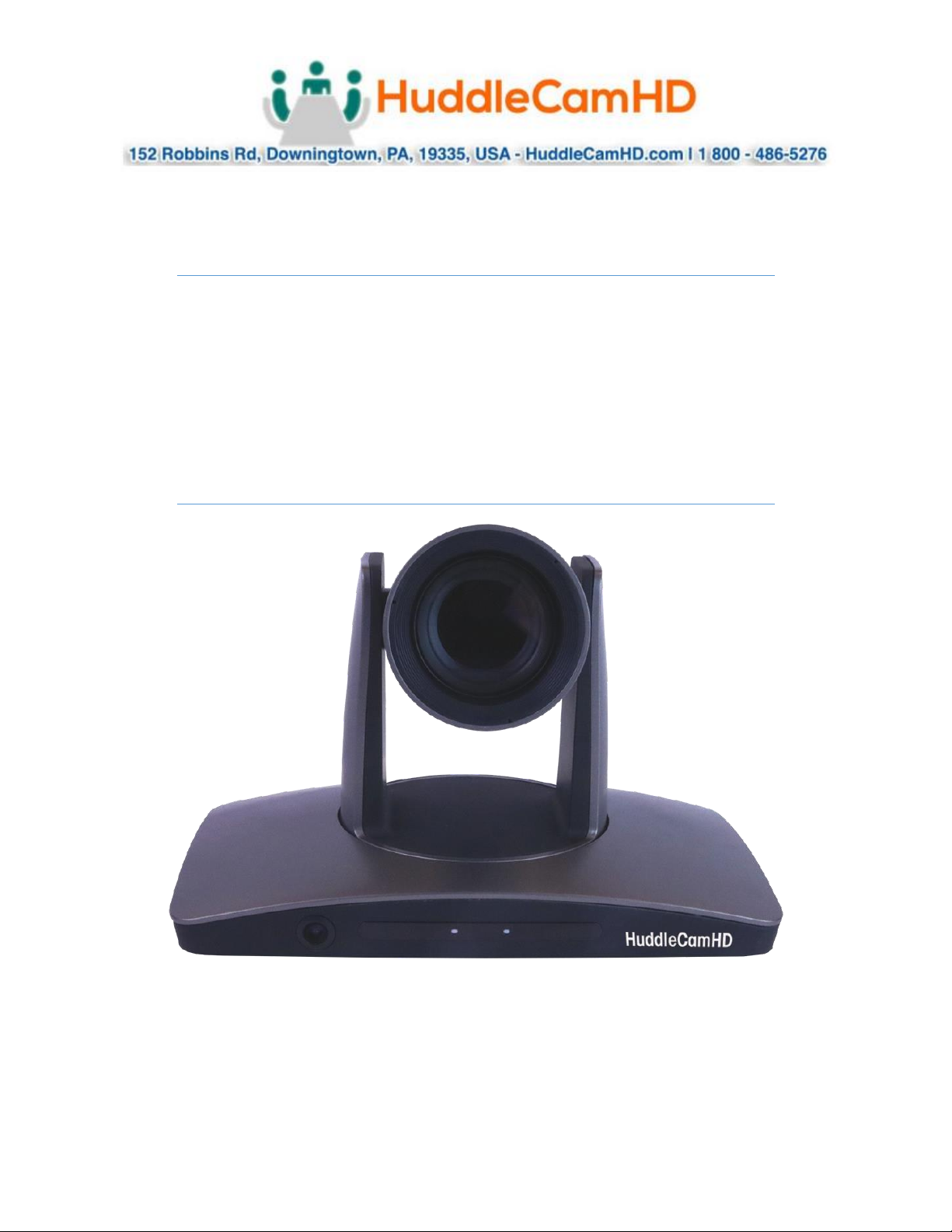
HuddleCamHD
HuddleView
Auto Framing Camera
Installation & Operation Manual
Page 2

Ver. 1.1 – 4-19
Page2
Table of Contents .
Precautions.…………………..………………………………………………….………..……………..………..………………
Page 3
Safety Tips…………………..……………..……………..……………..……………..……………..……………...........
Page 3
What’s in the Box……………..……………..………..…..……………..……………..……………..………………………
Page 3
Physical Descriptions.…………………..………………………………………………….………..……………..………….
Page 4
Front View of Camera……………..……………..……………..……………..……………..………………………….
Page 4
Rear View of Camera……………..………………....……………..……………..……………..………………………
Page 5
Basic Connection Instructions.…………………..………………………………………………….………..……………
Page 6
Network setup……………..……………..……………..……………..……………..……………..……………..….…..
Page 6
SDI Connections……………..……………..……………..……………..……………..……………..………………..…
Page 6
USB Connection……………..……………..……………..……………..……………..……………..………………...…
Page 6
DVI Connection.…………………..………………………………………………….………..……………..………..……
Page 6
Interface Descriptions.…………………..………………………………………………….………..……………..………..
Page 7
Tracking Software.…………………..………………………………………………….………..……………..…………
Page 7
Device Management Interface……………..……………..……………..……………..……………..……….
Page 7
Connect Camera……………..……………..……………..……………..………………………..………..………..
Page 9
Network Configuration……………..………………..……………..……………..……………..………………..
Page 10
Remote Configuration……………..……………..………………………..………………..………………………
Page 10
Remove Camera……………..……………..……………..……………..………………………..………..…………
Page 13
Configure Video Settings……………..……………..……………..……………..………………………..……..
Page 14
On Screen Display (OSD)
Page 17
Video……………..……………..………..……………..……………..……………..……………..…………..………..
Page 17
Exposure……………..……..……………..……………..………….……..……………..……………..…….………..
Page 17
White Balance……………..……..…………….…..……………..……………..……………..……………………..
Page 18
Pan Tilt Zoom……………..………..……………..……………..……………..……………..…………………..…..
Page 18
Systems……………..…………..…………..……………..……………..……………..……………..………………..
Page 19
Status……………..……………..………..……………..……………..……………..……………..……………….…..
Page 19
Restore Defaults……………..……………..………..……………..……………..…………………..……………..
Page 19
Using the IR Remote.…………………..………………………………………………….………..……………..…………..
Page 20
VISCA Commands.…………………..………………………………………………….………..……………..………..…….
Page 22
ACK / Completion……………..……………..……………..……………..……………..……………..………..……….
Page 22
Error Messages……………..……………..……………..……………..……………..……………..……………..……..
Page 22
Commands……………..……………..……………..……………..……………..……………..……………………..……
Page 23
Inquiry Commands……………..……………..……………..……………..……………..……………..…..…………..
Page 26
Tips & Tricks……………..………..…..……………..……………..……………..……………..…………………………...…
Page 28
Care of the Unit……………..……………..…………....……………..……………..……………..……………………..….
Page 28
Troubleshooting……………..……………..……………..……………..……………..……………..…………………..……
Page 29
Notes……………………………………………………………………………………………………………..……………………..
Page 30
Page 3

Ver. 1.1 – 4-19
Page3
Precautions .
Safety Tips .
• Please read this manual carefully before using the camera.
• Avoid damage from stress, violent vibration or liquid intrusion during
transportation, storage, or installation.
• Take care of the camera during installation to prevent damage to the camera
case, ports, lens, or PTZ mechanism.
• Do not apply excessive voltage, use only the specified voltage. Otherwise, you
may experience an electrical shock.
• Keep the camera away from strong electromagnetic sources.
• Do not aim the camera at bright light sources (e.g. bright lights, the sun, etc.) for
extended periods of time.
• Do not clean the camera with any active chemicals or corrosive detergents.
• Do not disassemble the camera or any of the camera's components. If problems
arise, please contact your authorized dealer.
• After long term operation, moving components can wear down. Contact your
authorized dealer for repair.
What’s in the Box .
Supplied Hardware .
• 12X HuddleView Camera
• Power Supply
• 3m / 9.8’ USB 3.0 A-B Cable
• User Manual
• IR Remote
• RS-232 control cable
• Software Installation Disk
Page 4
Ver. 1.1 – 4-19
Page4
Physical Descriptions .
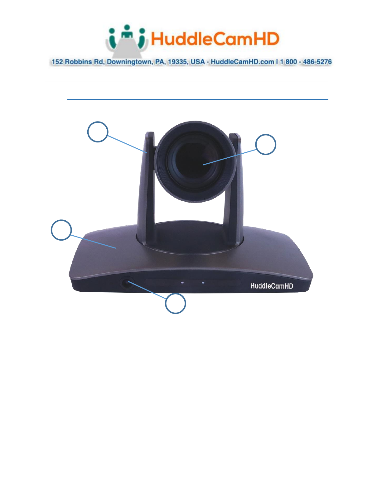
Front View of Camera .
1. Tracking Camera Head
2. Tracking Camera Lens
12X Optical Zoom
Field of View: 6.3°(Tele) ~ 72.5° (Wide)
3. Reference Camera Body
4. Reference Camera Lens
Fixed 2.4mm Lens
Field of View: 86° (Horizontal) / 52° (Vertical)
1
2
3
4
Page 5
Ver. 1.1 – 4-19
Page5
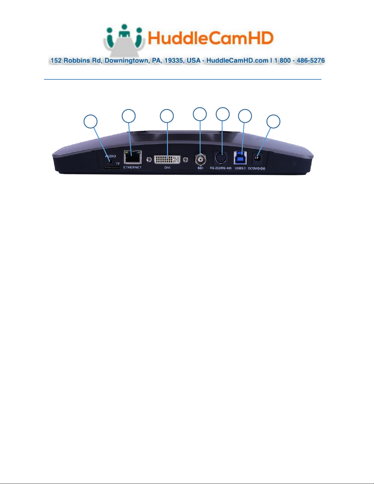
Back of the Camera .
1. Audio Line in
a. Embeds over IP Stream
2. Network Connection
a. Allows for software connection & RTSP/RTMP Streaming
3. DVI-D Connection
4. 3G-SDI Connection
5. VISCA Connection
a. Allows for joystick control of camera
6. USB 3.0 Connection
a. Note: IP Stream, DVI-D, 3G-SDI, & USB 3.0 connections are all simultaneous
7. DC12V Power Connection
3
5
6
Page 6

Ver. 1.1 – 4-19
Page6
Basic Connection Instructions .
To Configure the Camera .
1. Connect a live network connection, from a network with a DHCP server, to the camera.
2. Connect the included Power Supply to the camera.
3. Wait for camera to come to Home Position.
4. Install the HuddleView software on your Windows PC on the same network as the camera
5. Open the HuddleView software to connect to your camera
Note: To pull the main RTSP stream please use the following URL
rtsp://<camera ip>:<rtsp port>/main.h264
(example: rtsp://192.168.111.85:3750/main.h264)
Note: To pull the sub RTSP stream please use the following URL
rtsp://<camera ip>:<rtsp port>/sub.h264
(example: rtsp://192.168.111.85:3750/sub.h264)
Note: To pull the low quality 3rd or 4th RTSP stream please use the following URL
rtsp://<camera ip>:<rtsp port>/<3 or 4>.h264
(example: rtsp://192.168.111.85:3750/<3 or 4>.h264)
SDI Connection .
1. Connect an SDI cable to the SDI output on the camera.
2. Connect the SDI cable to your equipment with an available SDI input.
a. Camera will auto adjust frame rate & resolution upon connecting to a video
software
USB Connection .
1. Connect a USB 3.0 cable to the USB output on the camera.
2. Connect the USB 3.0 output to an available USB 3.0 port on your PC
a. Camera will auto adjust frame rate & resolution upon connecting to a video
software
DVI Connection .
1. Connect a DVI cable to the DVI output of the camera.
2. Connect the DVI cable to your equipment with an available DVI input.
a. Camera will auto adjust frame rate & resolution upon connecting to a video
software
NOTE: Failure to follow these sequences may result in no connection.
Page 7
Ver. 1.1 – 4-19
Page7
Interface Descriptions .
Tracking Software .
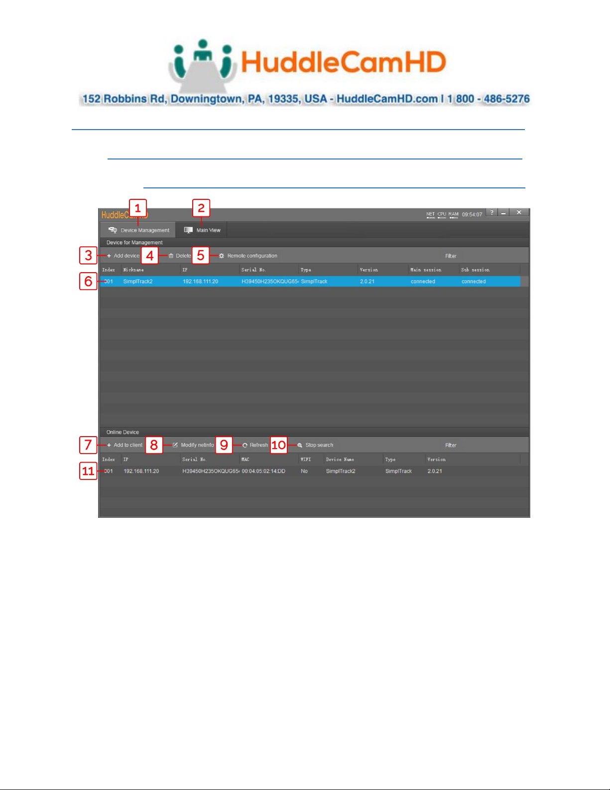
Device Management Interface .
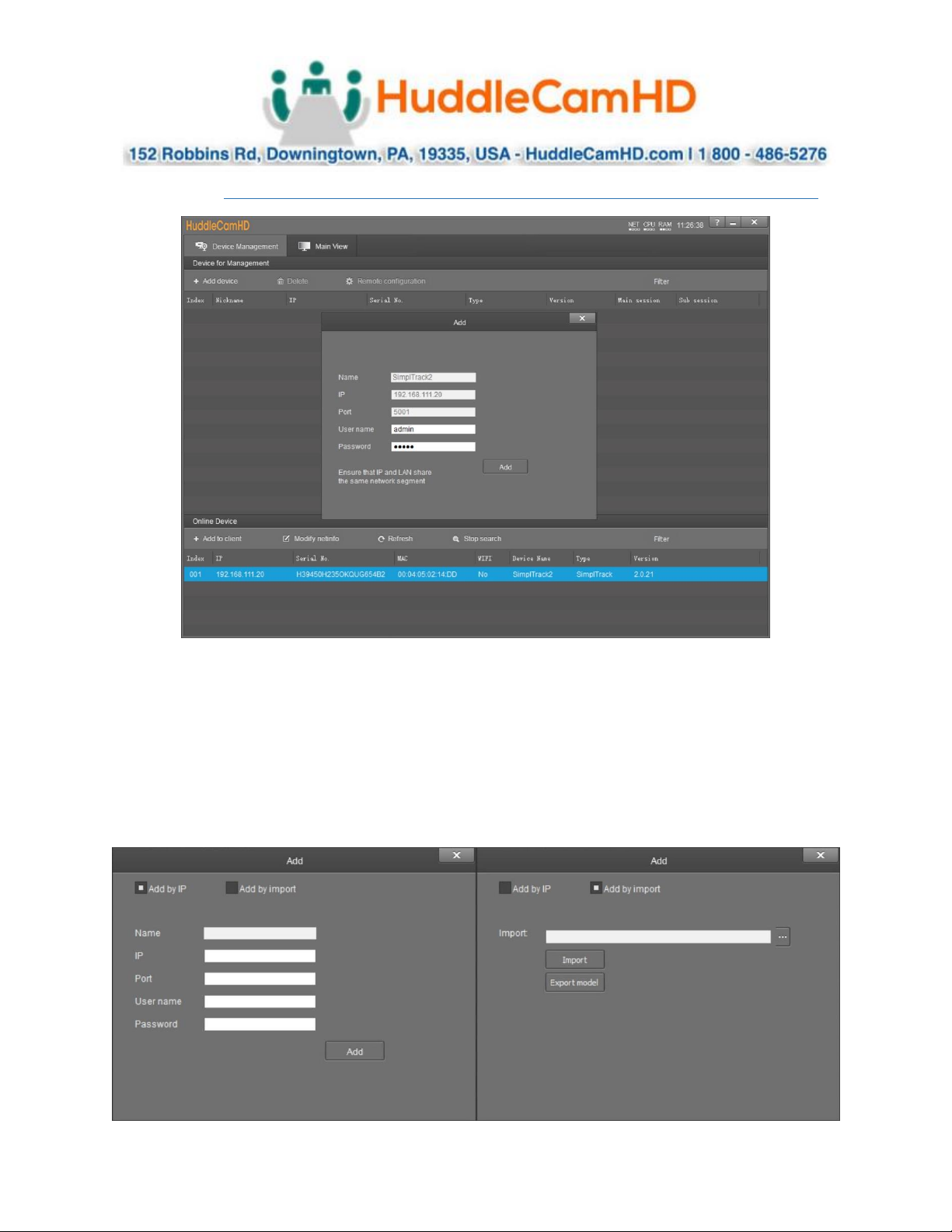
1
Device Management interface
7
Add selected camera from Online Device
section
2
Video configuration interface
8
Modify network settings of selected Online
Device
3
Manually add device using IP address, Port
number, Username & Password
9
Refresh Online Device list
4
Delete selected device from Device
Management list
10
Start/Stop searching for Online Devices
5
Configure network settings of camera
11
*Unselected* device from Online Device
section
6
*Selected* device within Device
Management
Page 8
Ver. 1.1 – 4-19
Page8
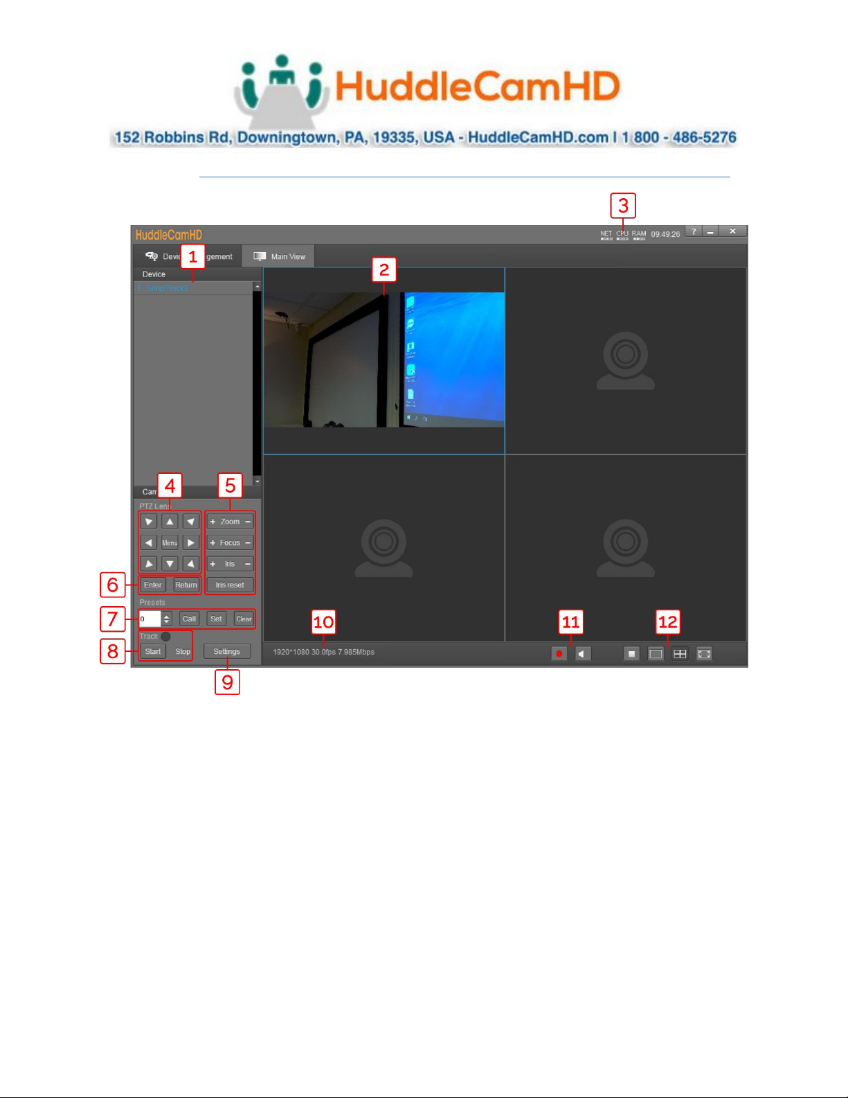
Video Configuration Interface .
1
Cameras connected to Device Management
7
Preset control
2
Camera video feed
8
Enable/Disable tracking
3
PC performance & time
9
Open tracking settings
4
Pan, Tilt, & OSD Menu control
10
Connected camera resolution & frame rate
5
Lens control
11
Enable/Disable recording
6
OSD Menu enter/return
12
Stop video, full screen, and gallery view
Page 9
Ver. 1.1 – 4-19
Page9
Connect Camera .
To add a camera to the Device Management list, you can go about this by searching in the Online
Device section, or by using the + Add Device button in the Device Management section.
When utilizing the Online Device section, you can simply click Search, and the Tracking Software will
automatically search your network for any HuddleView & SimplTrack2 cameras. Select the camera and
click + Add to Client to add it to the Device Management list.
When utilizing the + Add Device button within the Device Management section, you can connect your
camera through it’s IP address, Port number, Username & Password; or you can Import a *.csv file.
Page 10
Ver. 1.1 – 4-19
Page10
Network Configuration .
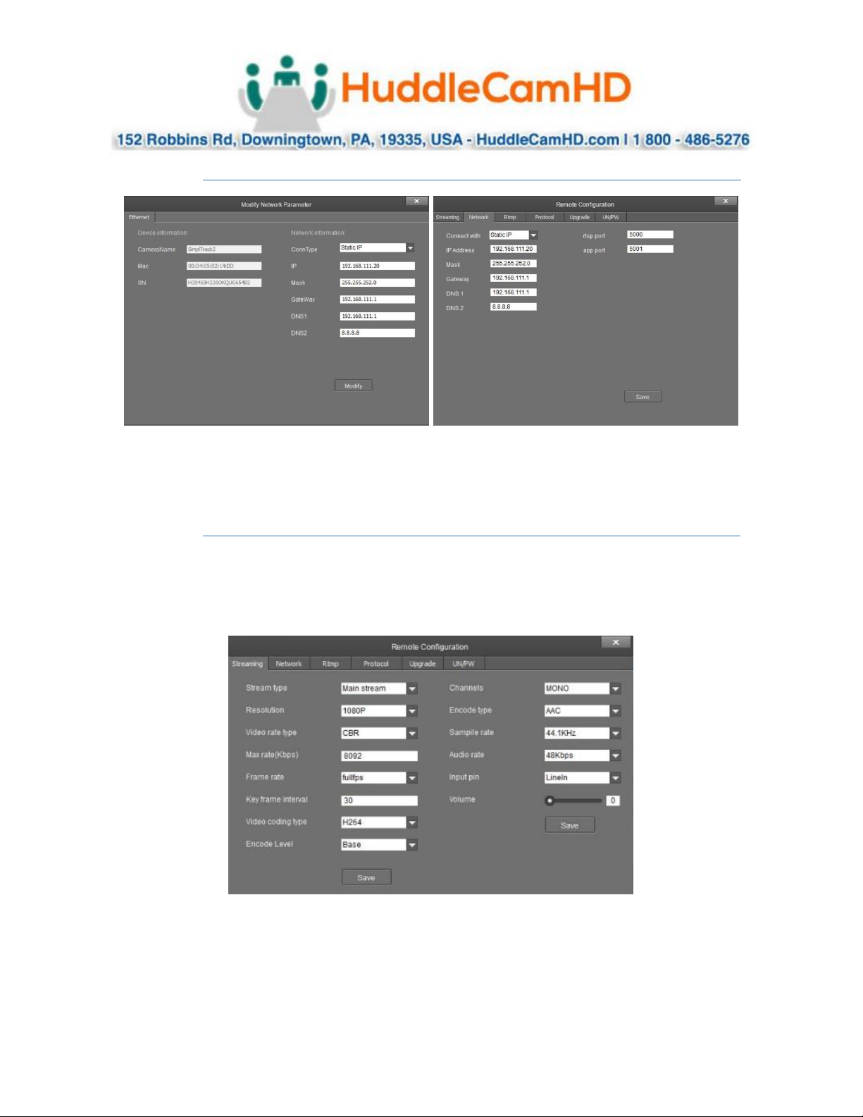
To configure the network settings, select the from the Online Device list and click Modify Netinfo. You
can also adjust the network settings of a connected camera by selecting it from the Device Management
list and clicking Remote Configuration, then traversing to the Network section.
Remote Configuration .
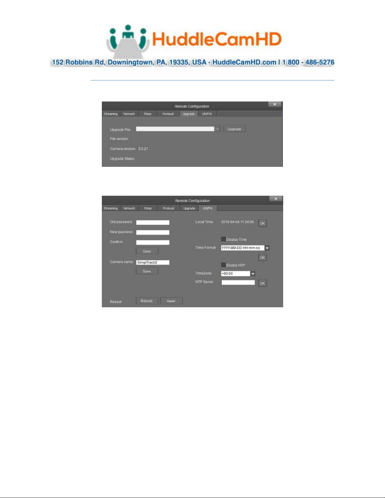
Remote Configuration includes: Streaming, Network, RTMP, Protocol, Upgrade, & Username/Password
The Streaming category allows you to configure the Main Stream (PTZ camera), Sub Stream (reference
camera), Stream 3 & Stream 4.
Page 11
Ver. 1.1 – 4-19
Page11
Remote Configuration (Continued) _
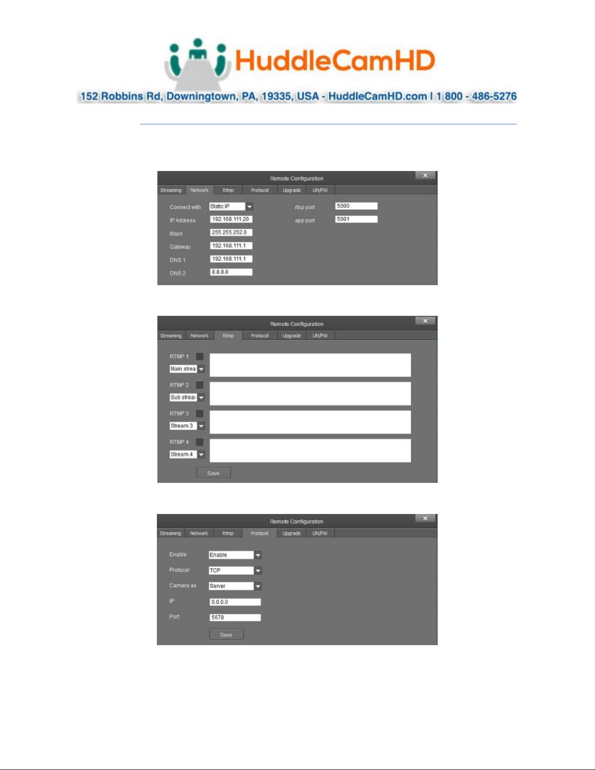
The Network category allows you to assign a dynamic or static IP address for the camera, in addition to
settings the port numbers for RTSP & control.
The RTMP category allows you to define a RTMP server.
The Protocol category allows you to set the control parameters of the camera.
Page 12
Ver. 1.1 – 4-19
Page12
Remote Configuration (Continued) _
The Upgrade category allows you to upgrade the firmware of the camera.
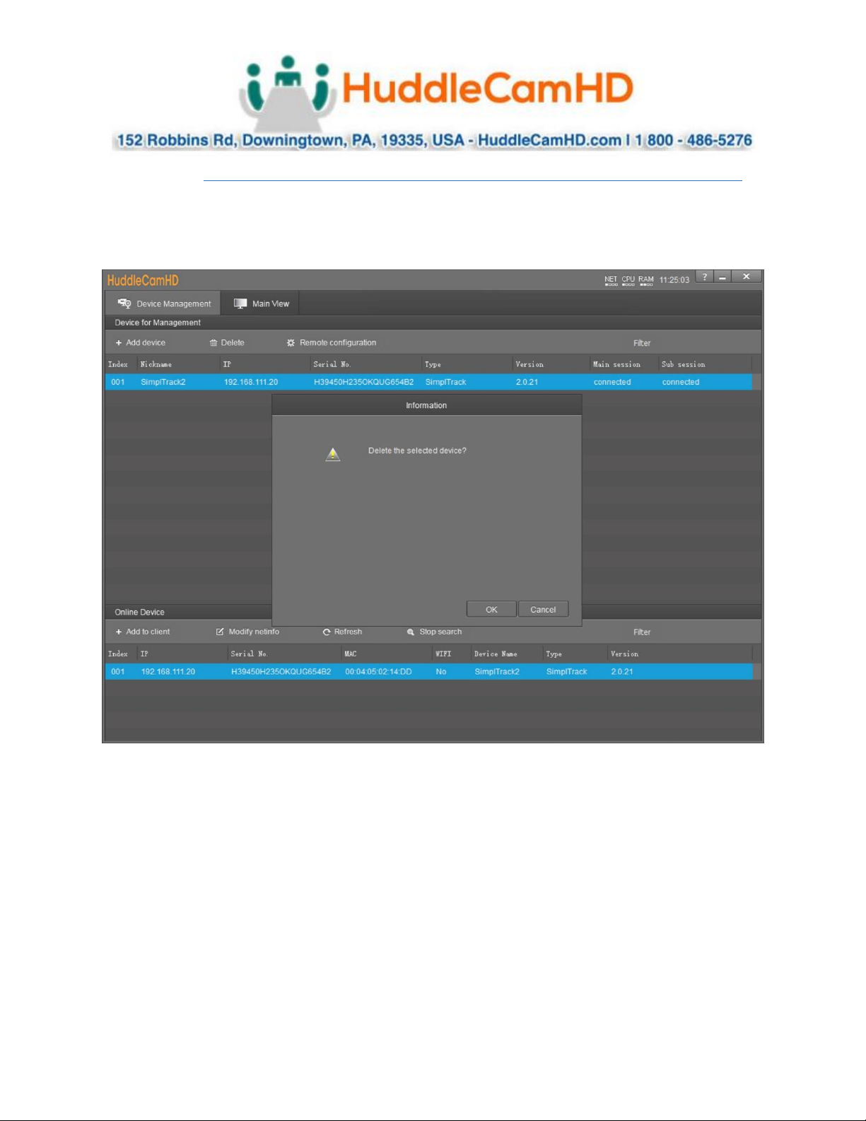
The Username/Password category allows you to change the device name, password, and adjust the
time format.
Page 13
Ver. 1.1 – 4-19
Page13
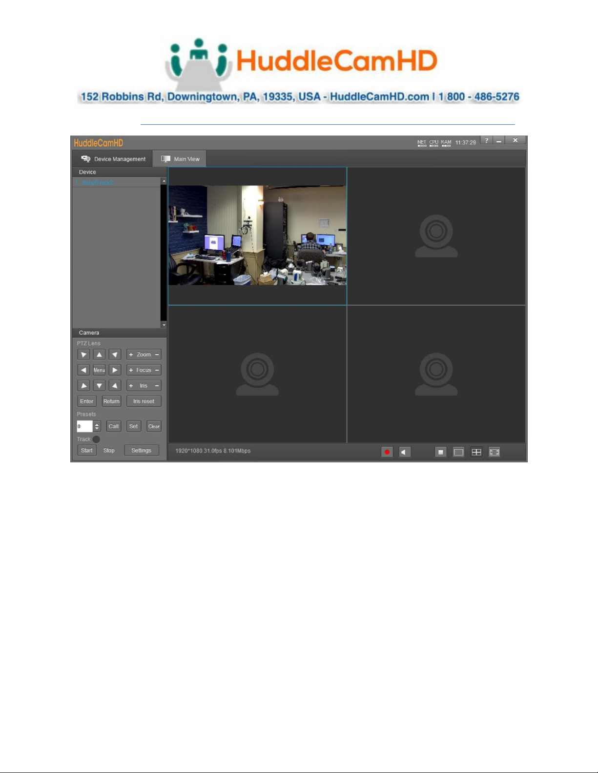
Remove Camera .
To remove a camera from the Device Management list, first select it, then click the Delete button above
the list. You will be prompted with a confirmation window to remove the camera. Click OK to remove
the device or Cancel to keep the current settings.
Page 14
Ver. 1.1 – 4-19
Page14
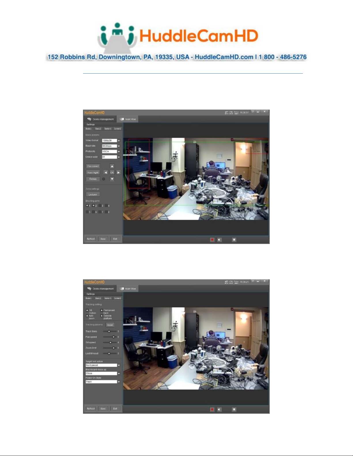
Configure Video Settings .
In the Video Interface you can view and control up to four cameras simultaneously. You have full control
over Pan, Tilt, Zoom, Focus, Iris, OSD Menu, Presets & Tracking Settings.
You must first select one of the cameras from the video feed in order to adjust the settings.
Page 15
Ver. 1.1 – 4-19
Page15
Configure Tracking Settings .
To adjust the Tracking Parameters of the selected camera, you must click the Settings button in the
tracking control area. Once opened, you can add and remove tracking & blocking zones, change video
resolution & frame rate, baud rate, control protocol, device address, and correct the position of camera.
Within Basic2 settings, you can enable or disable tilt, permanent track, auto zoom, & outside platform. In
addition, you can adjust the tracking sensitivity, pan speed, tilt speed, zoom limit, and what happens when
the camera loses its target.
Page 16
Ver. 1.1 – 4-19
Page16
Configure Tracking Settings (Continued) .
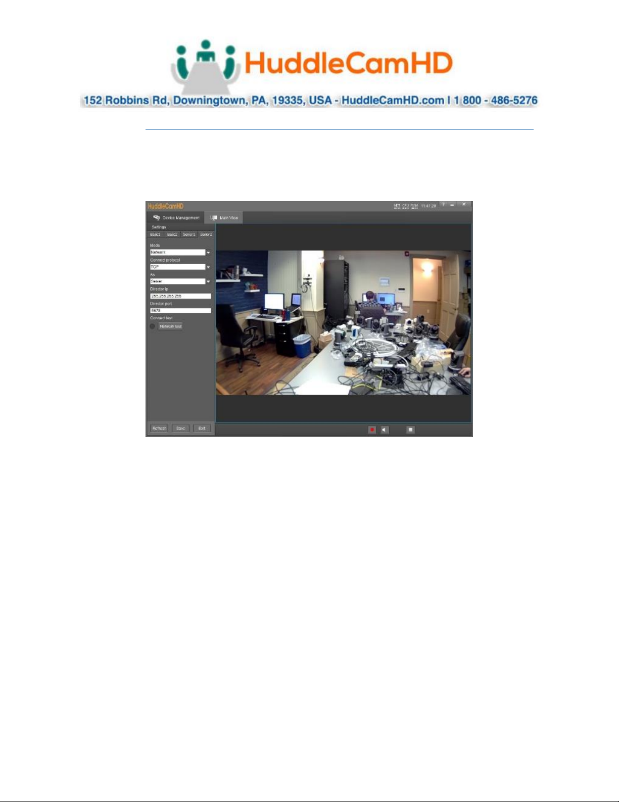
The Senior 1 settings tab is disabled and will be enabled with future updates.
Senior 2 allows for network control via TCP or UDP and allows the camera to act as a server or client for
receiving commands.
Page 17
Ver. 1.1 – 4-19
Page17
On Screen Display (OSD) .
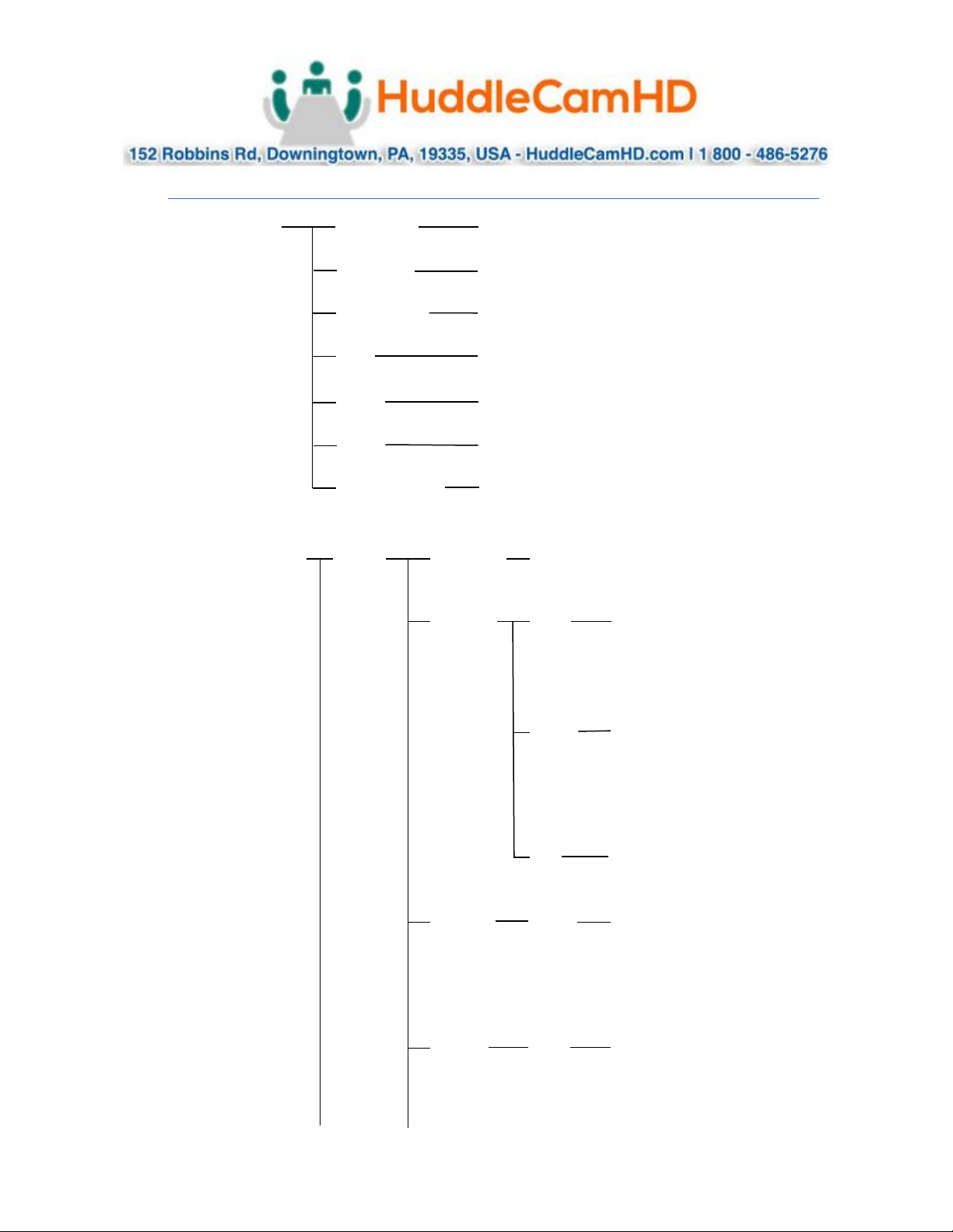
<VIDEO>
SHARPNESS
CONTRAST
0, 1, 2, 3, 4, 5, 6, 7, 8, 9, 10, 11, 12, 13, 14, 15
0, 1, 2, 3, 4, 5, 6, 7, 8, 9, 10, 11, 12, 13, 14
SATURATION
HUE
0, 1, 2, 3, 4, 5, 6, 7, 8, 9, 10, 11, 12, 13, 14
0, 1, 2, 3, 4, 5, 6, 7, 8, 9, 10, 11, 12, 13, 14
2DNR
3DNR
WIDE DYNAMIC
OFF, ON
OFF, ON, 1, 2, 3, 4
OFF, ON
<EXPOSURE>
MODE
FULL AUTO
ANTI-FLICKER
OFF, 50Hz, 60Hz
MANUAL
GAIN
0, 1, 2, 3, 4, 5, 6, 7, 8, 9,
10, 11, 12, 13, 14, 15,
16, 17, 18, 19, 20, 21,
22, 23, 24, 25, 26, 27,
28, 29, 30
SPEED
1/1, 1/25, 1/50, 1/75,
1/100, 1/120, 1/150,
1/215, 1/300, 1/425,
1/600, 1/1000, 1/1250,
1/1750, 1/2500, 1/3500,
1/6000, 1/10000
IRIS
F14, F11, F9.6, F8, F6.8,
F5.6, F4.8, F4, F3.4, F2.8,
F2.4, F2, F1.6, CLOSE
SHUTTER
PRI
SPEED
1/1, 1/25, 1/50, 1/75,
1/100, 1/120, 1/150,
1/215, 1/300, 1/425,
1/600, 1/1000, 1/1250,
1/1750, 1/2500, 1/3500,
1/6000, 1/10000
IRIS PRI
IRIS
F14, F11, F9.6, F8, F6.8,
F5.6, F4.8, F4, F3.4, F2.8,
F2.4, F2, F1.6, CLOSE
Page 18
Ver. 1.1 – 4-19
Page18
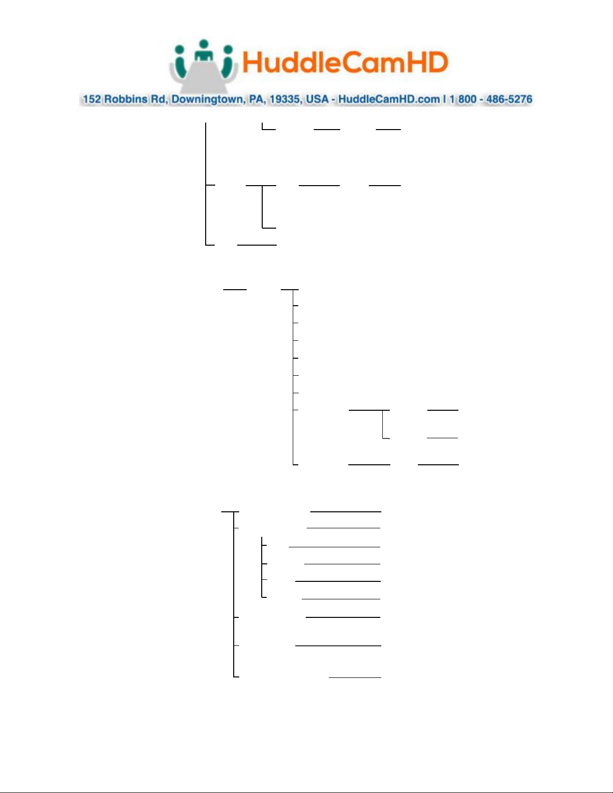
BRIGHT
PRI
BRIGHT
0, 1, 2, 3, 4, 5, 6, 7, 8, 9,
10, 11, 12, 13, 14, 15,
16, 17, 18, 19, 20, 21,
22, 23, 24, 25, 26, 27
EXP-
COMP
ON LEVEL
-7, -6, -5, -4, -3, -2, -1,
0, +1, +2, +3, +4, +5,
+6, +7
OFF
BLC ON, OFF
<WHITE BALANCE>
MODE
AUTO
ATW
ONE PUSH
INDOOR
OUTDOOR
SODIUM LAMP
FLUO LAMP
MANUAL
R.GAIN
0~255
B.GAIN
0~255
MANUAL2
GAIN
4600
<PAN TILT ZOOM>
PAN/TILT SPEED
1, 2, 3, 4, 5, 6, 7, 8
PAN/TILT LIMIT
ON, OFF
UP +90°~ -30°
DOWN
-30°~ +90°
LEFT -170°~ +170°
RIGHT
+170°~ -170°
D-ZOOM LIMIT
X1, X2, X3, X4, X5, X6, X7,
X8, X9, X10, X11, X12
PTZ TRIG AF
ON, OFF
POWER UP ACTION
PRESET 1, PRESET 2,
PRESET 3, PRESET 4,
PRESET 5, PRESET 6,
PRESET 7, PRESET 8,
PRESET 9, HOME
Page 19
Ver. 1.1 – 4-19
Page19
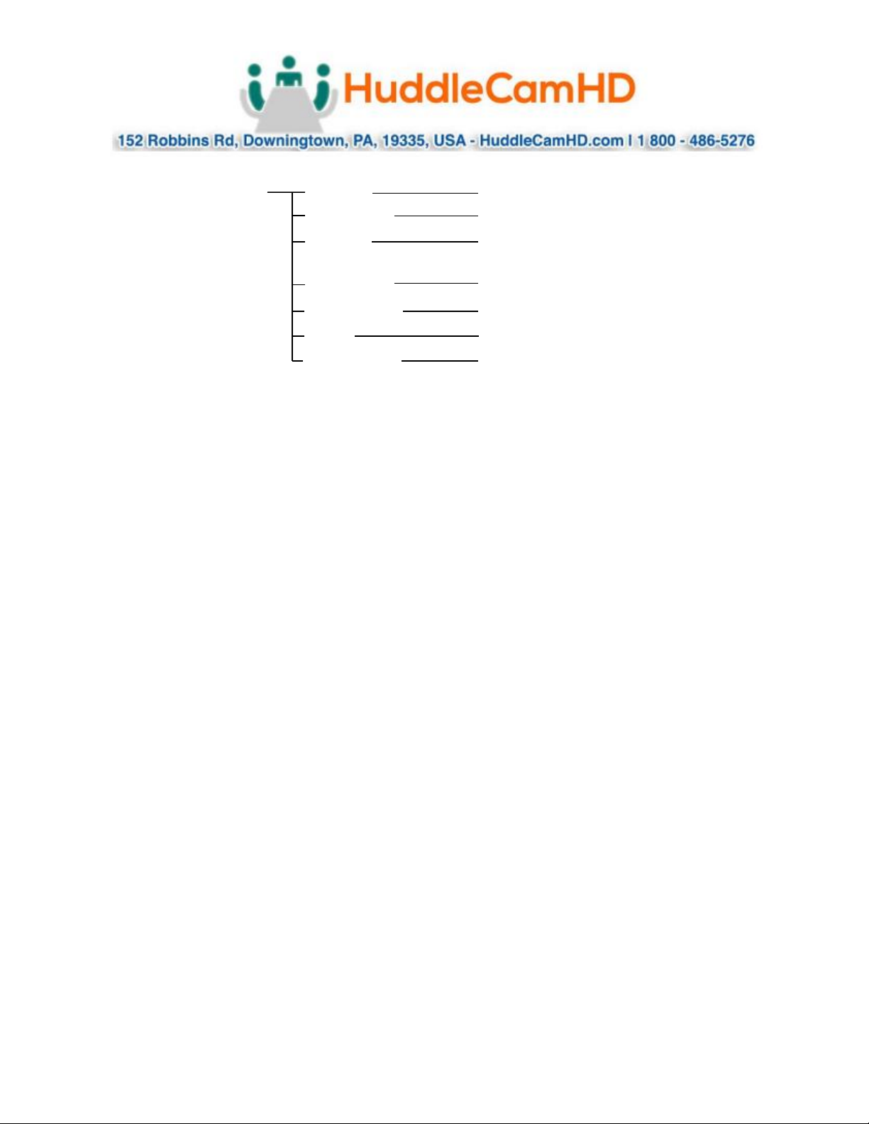
<SYSTEM>
ADDRESS
1, 2, 3, 4, 5, 6, 7
PROTOCOL
VISCA, PELCO-D
FORMAT
1080p60/50/30/25, 1080i60/50,
720p60/50
RATIO SPEED
OFF, ON
PRESET FREEZE
OFF, ON
RS485
HALF-DUPLEX-1, HALF-DUPLEX-2
DISPLAY INFO
OFF, ON
<STATUS>
SHOWS CURRENT SETTINGS OF CAMERA
<RESTORE DEFAULTS>
Page 20
Ver. 1.1 – 4-19
Page20
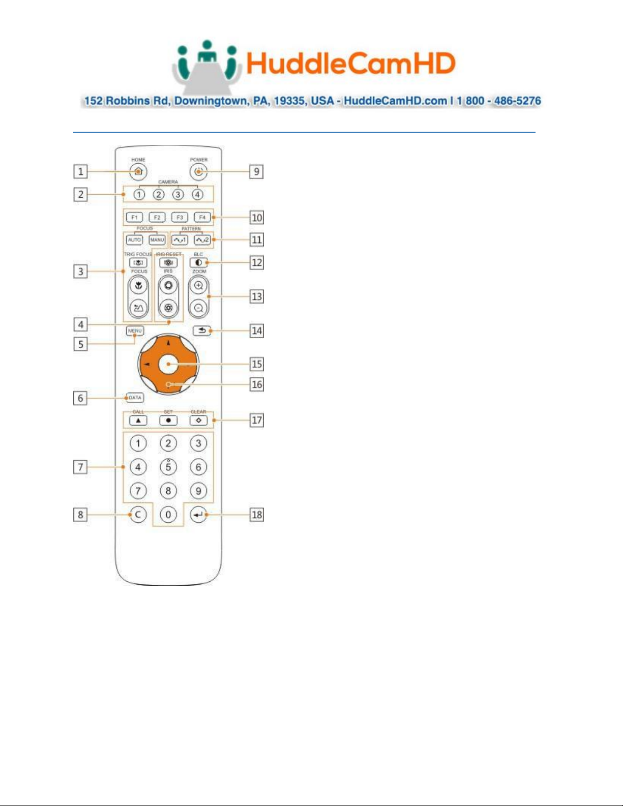
Using the IR Remote .
1. HOME Button
Press the HOME Button to send the camera to the
initial position where pan and tilt is 0.
2. Camera Selection Button
Use to switch between IR channels for multiple
camera control. For example, 4 is address 4.
3. Focus
Use “AUTO” or “MANU” to select auto or manual
focus. Trig Focus enables auto focus whenever the
camera is zoomed. Near/Far allows for focus
adjustment while in manual focus.
4. Iris
Press Iris Reset to set iris back to default value or
use Open/Close to open and close the Iris.
5. Menu
Use to open/close the OSD Menu.
6. Data Button
Use the Data Button to enable/disable display of
pan/tilt angle, zoom time, and other prompt
messages.
7. Number Keys
Used for inputting numbers such as preset number.
8. Cancel Button
Cancel number input.
9. Power Button
User to power on/off the camera.
10. Shortcut Buttons (F1, F2, F3, F4)
Use these buttons for shortcut commands. (Shown
below)
11. Pattern Buttons
Use to activate Pattern Scan 1 and Pattern Scan 2
12. BLC Button
Use to enable/disable Backlight Compensation.
13. Zoom buttons
Use to zoom in or zoom out.
14. Back Button
Use the Back Button to go back to the previous menu
15. OK Button
In OSD Menu: select the corresponding option
Out of OSD Menu: adjust pan/tilt control speed
Page 21

Ver. 1.1 – 4-19
Page21
16. Direction/Menu Operation
In OSD Menu: traverse OSD Menu
Out of OSD Menu: pan & tilt camera
17. Preset Settings
Use the Number Keys to input a preset number, then press call, store, clear to perform the
corresponding command.
18. Enter
After inputting numbers, press this button to confirm.
IR Remote Shortcuts _
• [F1] > [1] > [ENTER] - Change camera to Device Address 1
• [F1] > [2] > [ENTER] - Change camera to Device Address 2
• [F1] > [3] > [ENTER] - Change camera to Device Address 3
• [F1] > [4] > [ENTER] - Change camera to Device Address 4
• [F1] > [5] > [ENTER] - Start Tracking
• [F1] > [6] > [ENTER] - End Tracking
Page 22
Ver. 1.1 – 4-19
Page22
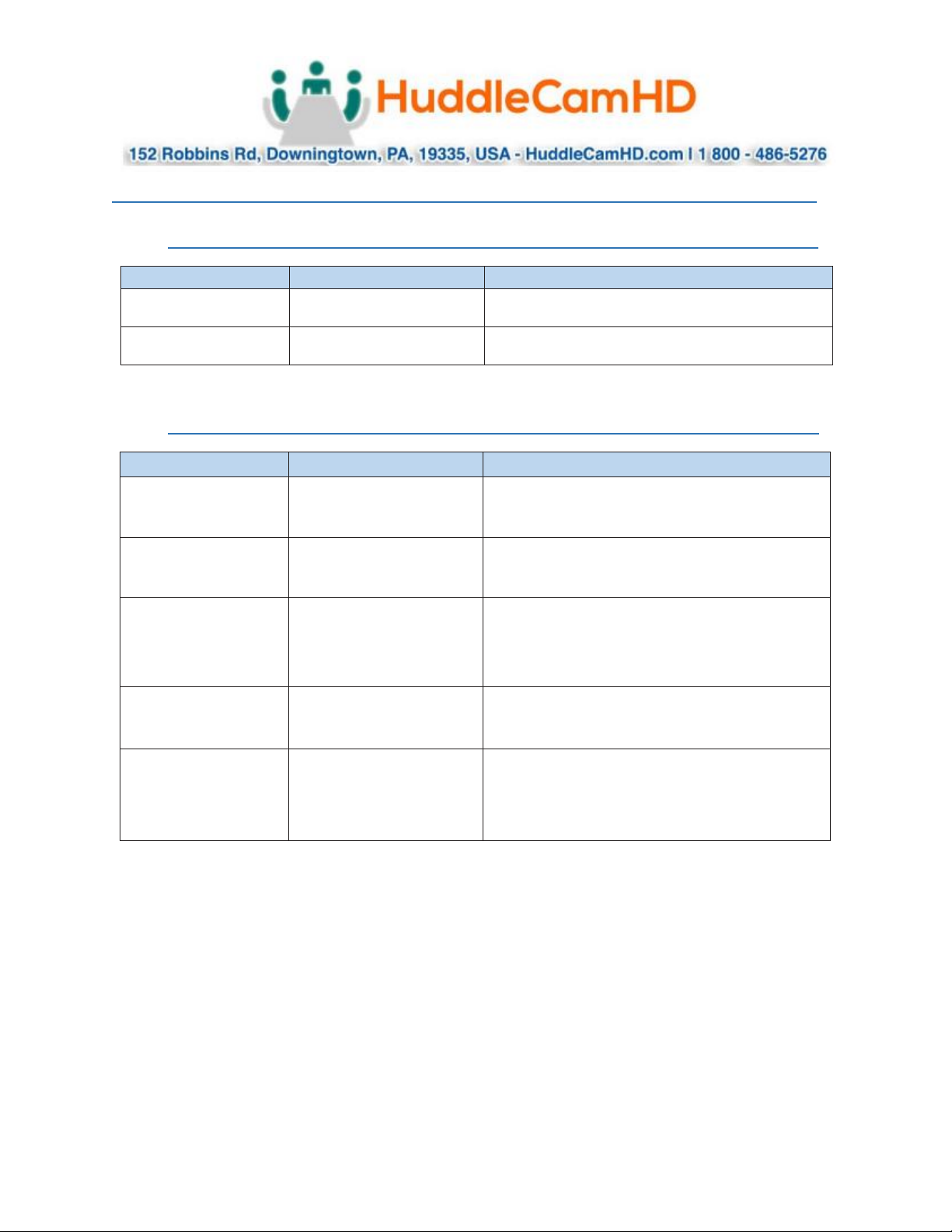
VISCA Commands .
ACK/Completion Messages .
Command Messages
Comments
ACK
z0 4y FF
(y:Socket No.)
Returned when the command is accepted.
Completion
z0 5y FF
(y:Socket No.)
Returned when the command has been executed.
Error Messages .
Command Messages
Comments
Syntax Error
z0 60 02 FF
Returned when the command format is different or when a
command with illegal
command parameters is accepted.
Command Buffer Full
z0 60 03 FF
Indicates
that two sockets are already being used
(executing
two
commands)
and the
command could not be accepted when received.
Command Canceled
z0 6y 04 FF
(y:Socket No.)
Returned when a command which is being executed in a
socket specified by the cancel command is canceled. The
completion message for the command is not
returned.
No Socket
z0 6y 05 FF
(y:Socket No.)
Returned when no command is executed in a socket specified by the
cancel
command, or when an invalid socket number is specified.
Command Not Executable
z0 6y 41 FF
(y:Execution command
Socket No. Inquiry command:0)
Returned when a command cannot be executed due to current
conditions. For
example, when commands controlling the focus manually are
received during auto focus.
z = Device address + 8
Page 23
Ver. 1.1 – 4-19
Page23
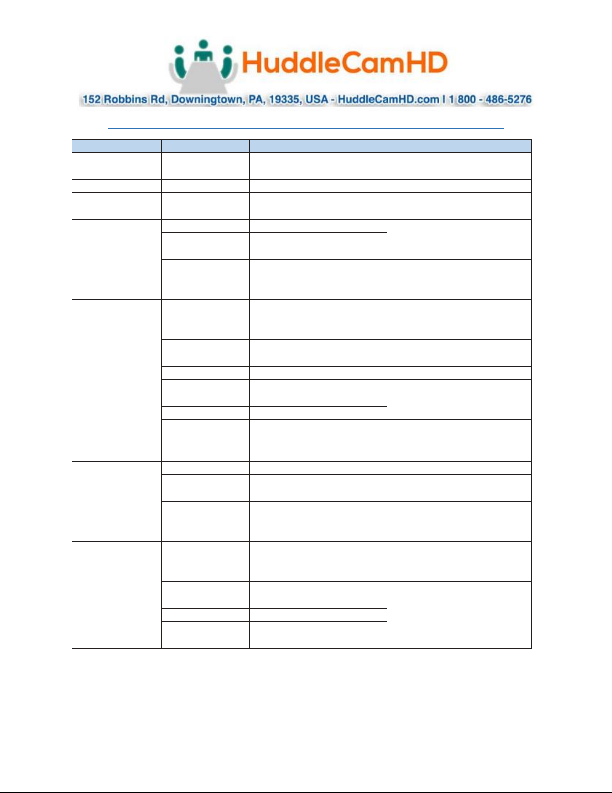
Commands .
Command Set
Command
Command Packet
Comments
AddressSet
Broadcast
88 30 01 FF
Address setting
IF_Clear
Broadcast
88 01 00 01 FF
I/F Clear
CommandCancel
8x 2p FF
p: Socket No.(=1or2)
CAM_Power
On
8x 01 04 00 02 FF
Power ON/OFF
Off
8x 01 04 00 03 FF
CAM_Zoom
Stop
8x 01 04 07 00 FF
Tele(Standard)
8x 01 04 07 02 FF
Wide(Standard)
8x 01 04 07 03 FF
Tele(Variable)
8x 01 04 07 2p FF
p=0 (Low) to 7 (High)
Wide(Variable)
8x 01 04 07 3p FF
Direct
8x 01 04 47 0p 0q 0r 0s FF
pqrs: Zoom Position
CAM_Focus
Stop
8x 01 04 08 00 FF
Far(Standard)
8x 01 04 08 02 FF
Near(Standard)
8x 01 04 08 03 FF
Far(Variable)
8x 01 04 08 2p FF
p=0 (Low) to 7 (High)
Near(Variable)
8x 01 04 08 3p FF
Direct
8x 01 04 48 0p 0q 0r 0s FF
pqrs: Focus Position
Auto Focus
8x 01 04 38 02 FF
AF ON/OFF
Manual Focus
8x 01 04 38 03 FF
Auto/Manual
8x 01 04 38 10 FF
One Push Trigger
8x 01 04 18 01 FF
One Push AF Trigger
CAM_ZoomFocus
Direct
8x 01 04 47 0p 0q 0r 0s
0t 0u 0v 0w FF
pqrs: Zoom Position
tuvw: Focus Position
CAM_WB
Auto
8x 01 04 35 00 FF
Normal Auto
Indoor
8x 01 04 35 01 FF
Indoor mode
Outdoor
8x 01 04 35 02 FF
Outdoor mode
One Push WB
8x 01 04 35 03 FF
One Push WB mode
Manual
8x 01 04 35 05 FF
Manual Control mode
One push trigger
8x 01 04 10 05 FF
One Push WB Trigger
CAM_RGain
Reset
8x 01 04 03 00 FF
Manual Control of R Gain
Up
8x 01 04 03 02 FF
Down
8x 01 04 03 03 FF
Direct
8x 01 04 43 00 00 0p 0q FF
pq: R Gain
CAM_BGain
Reset
8x 01 04 04 00 FF
Manual Control of B Gain
Up
8x 01 04 04 02 FF
Down
8x 01 04 04 03 FF
Direct
8x 01 04 44 00 00 0p 0q FF
pq: B Gain
Page 24
Ver. 1.1 – 4-19
Page24
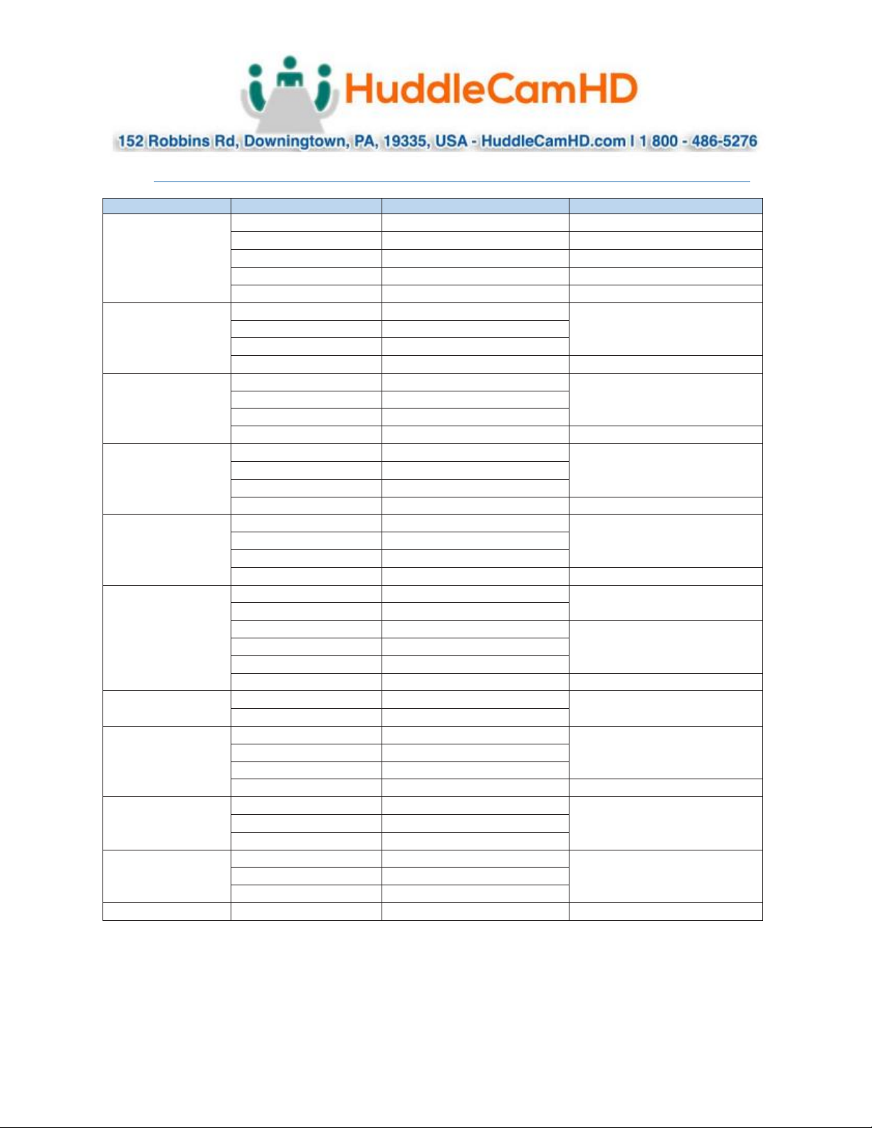
Commands (Continued) .
Command Set
Command
Command Packet
Comments
CAM_AE
Full Auto
8x 01 04 39 00 FF
Automatic Exposure mode
Manual
8x 01 04 39 03 FF
Manual Control mode
Shutter Priority
8x 01 04 39 0A FF
Shutter Priority Automatic Exposure
Iris Priority
8x 01 04 39 0B FF
Iris Priority Automatic Exposure mode
Bright
8x 01 04 39 0D FF
Bright Mode (Manual control)
CAM_Shutter
Reset
8x 01 04 0A 00 FF
Shutter Setting
Up
8x 01 04 0A 02 FF
Down
8x 01 04 0A 03 FF
Direct
8x 01 04 4A 00 00 0p 0q FF
pq: Shutter Position
CAM_Iris
Reset
8x 01 04 0B 00 FF
Iris Setting
Up
8x 01 04 0B 02 FF
Down
8x 01 04 0B 03 FF
Direct
8x 01 04 4B 00 00 0p 0q FF
pq: Iris Position
CAM_Gain
Reset
8x 01 04 0C 00 FF
Gain Setting
Up
8x 01 04 0C 02 FF
Down
8x 01 04 0C 03 FF
Direct
8x 01 04 4C 00 00 0p 0q FF
pq: Gain Position
CAM_Bright
Reset
8x 01 04 0D 00 FF
Bright Setting
Up
8x 01 04 0D 02 FF
Down
8x 01 04 0D 03 FF
Direct
8x 01 04 4D 00 00 0p 0q FF
pq: Bright Position
CAM_ExpComp
On
8x 01 04 3E 02 FF
Exposure Compensation ON/OFF
Off
8x 01 04 3E 03 FF
Reset
8x 01 04 0E 00 FF
Exposure Compensation Amount
Setting
Up
8x 01 04 0E 02 FF
Down
8x 01 04 0E 03 FF
Direct
8x 01 04 4E 00 00 0p 0q FF
pq: ExpComp Position
CAM_Backlight
On
8x 01 04 33 02 FF
Back Light Compensation ON/OFF
Off
8x 01 04 33 03 FF
CAM_Aperture
Reset
8x 01 04 02 00 FF
Aperture Control
Up
8x 01 04 02 02 FF
Down
8x 01 04 02 03 FF
Direct
8x 01 04 42 00 00 0p 0q FF
pq: Aperture Gain
CAM_PictureEffect
Off
8x 01 04 63 00 FF
Picture Effect Setting
Neg.Art
8x 01 04 63 02 FF
B&W
8x 01 04 63 04 FF
CAM_Memory
Reset
8x 01 04 3F 00 pp FF
pp: Memory Number (=0 to 255)
Corresponds to 0 to 255 on the
Remote Commander.
Set
8x 01 04 3F 01 pp FF
Recall
8x 01 04 3F 02 pp FF
SYS_Menu
Off
8x 01 06 06 03 FF
Turns off the menu screen.
Page 25
Ver. 1.1 – 4-19
Page25
Commands (Continued) .
Command Set
Command
Command Packet
Comments
CAM_IDWrite
8x 01 04 22 0p 0q 0r 0s FF
pqrs: Camera ID (=0000 to FFFF)
IR_Receive
On
8x 01 06 08 02 FF
IR(remote commander) receive
ON/OFF
Off
8x 01 06 08 03 FF
Information Display
On
8x 01 7E 01 18 02 FF
ON/OFF of the Operation status
display
Off
8x 01 7E 01 18 03 FF
Pan-tiltDrive
Up
8x 01 06 01 VV WW 03 01 FF
VV: Pan speed 0 x01 (low
speed) to 0 x18 (high speed)
WW: Tilt Speed 0 x 01 (low
speed) to 0 x14 (high speed)
YYYY: Pan Position
ZZZZ: Tilt Position
Down
8x 01 06 01 VV WW 03 02 FF
Left
8x 01 06 01 VV WW 01 03 FF
Right
8x 01 06 01 VV WW 02 03 FF
UpLeft
8x 01 06 01 VV WW 01 01 FF
UpRight
8x 01 06 01 VV WW 02 01 FF
DownLeft
8x 01 06 01 VV WW 01 02 FF
DownRight
8x 01 06 01 VV WW 02 02 FF
Stop
8x 01 06 01 VV WW 03 03 FF
AbsolutePosition
8x 01 06 02 VV WW
0Y 0Y 0Y 0Y 0Z 0Z 0Z 0Z FF
RelativePosition
8x 01 06 03 VV WW
0Y 0Y 0Y 0Y 0Z 0Z 0Z 0Z FF
Home
8x 01 06 04 FF
Reset
8x 01 06 05 FF
Pan-tiltLimitSet
LimitSet
8x 01 06 07 00 0W
0Y 0Y 0Y 0Y 0Z 0Z 0Z 0Z FF
W: 1 UpRight 0: DownLeft
YYYY: Pan Limit Position
ZZZZ: Tilt Position
CAM_AutoFrameTrigger
One Push Auto Frame
8x 01 0E 24 6C 0p 0p FF
P: seconds
Page 26
Ver. 1.1 – 4-19
Page26
Inquiry Commands .
Inquiry Command
Command Packet
Inquiry Packet
Comments
CAM_PowerInq
8x 09 04 00 FF
y0 50 02 FF
On
y0 50 03 FF
Off (Standby)
y0 50 04 FF
Internal power circuit error
CAM_ZoomPosInq
8x 09 04 47 FF
y0 50 0p 0q 0r 0s FF
pqrs: Zoom Position
CAM_FocusModeInq
8x 09 04 38 FF
y0 50 02 FF
Auto Focus
y0 50 03 FF
Manual Focus
CAM_FocusPosInq
8x 09 04 48 FF
y0 50 0p 0q 0r 0s FF
pqrs: Focus Position
CAM_WBModeInq
8x 09 04 35 FF
y0 50 00 FF
Auto
y0 50 01 FF
In Door
y0 50 02 FF
Out Door
y0 50 03 FF
One Push WB
y0 50 05 FF
Manual
CAM_RGainInq
8x 09 04 43 FF
y0 50 00 00 0p 0q FF
pq: R Gain
CAM_BGainInq
8x 09 04 44 FF
y0 50 00 00 0p 0q FF
pq: B Gain
CAM_AEModeInq
8x 09 04 39 FF
y0 50 00 FF
Full Auto
y0 50 03 FF
Manual
y0 50 0A FF
Shutter Priority
y0 50 0B FF
Iris Priority
y0 50 0D FF
Bright
CAM_ShutterPosInq
8x 09 04 4A FF
y0 50 00 00 0p 0q FF
pq: Shutter Position
CAM_IrisPosInq
8x 09 04 4B FF
y0 50 00 00 0p 0q FF
pq: Iris Position
CAM_GainPosInq
8x 09 04 4C FF
y0 50 00 00 0p 0q FF
pq: Gain Position
CAM_BrightPosInq
8x 09 04 4D FF
y0 50 00 00 0p 0q FF
pq: Bright Position
CAM_ExpCompModeInq
8x 09 04 3E FF
y0 50 02 FF
On
y0 50 03 FF
Off
CAM_ExpCompPosInq
8x 09 04 4E FF
y0 50 00 00 0p 0q FF
pq: ExpComp Position
CAM_BacklightModeInq
8x 09 04 33 FF
y0 50 02 FF
On
y0 50 03 FF
Off
CAM_ApertureInq
8x 09 04 42 FF
y0 50 00 00 0p 0q FF
pq: Aperture Gain
CAM_PictureEffectModeInq
8x 09 04 63 FF
y0 50 00 FF
Off
y0 50 02 FF
Neg.Art
y0 50 04 FF
B&W
CAM_MemoryInq
8x 09 04 3F FF
y0 50 0p FF
p: Memory number last operated.
SYS_MenuModeInq
8x 09 06 06 FF
y0 50 02 FF
On
y0 50 03 FF
Off
CAM_IDInq
8x 09 04 22 FF
y0 50 0p 0q 0r 0s FF
pqrs: Camera ID
Page 27
Ver. 1.1 – 4-19
Page27
Inquiry Commands (Continued) .
Inquiry Command
Command Packet
Inquiry Packet
Comments
CAM_VersionInq
8x 09 00 02 FF
y0 50 00 01
mn pq rs tu vw FF
mnpq: Model Code (0504)
rstu: ROM version
vw: Socket Number (=02)
Information Display
8x 09 7E 01 18 FF
y0 50 02 FF
On
y0 50 03 FF
Off
VideoSystemInq
8x 09 06 23 FF
y0 50 00 FF
1920 x1080i/60
60 Hz system
y0 50 01 FF
1920 x1080p/30
y0 50 02 FF
1280 x720p/60
y0 50 03 FF
1280 x720p/30
y0 50 07 FF
1920 x1080p/60
y0 50 08 FF
1920 x1080i/50
50 Hz system
y0 50 09 FF
1920 x1080p/25
y0 50 0A FF
1280 x720p/50
y0 50 0B FF
1280 x 720p/25
y0 50 0F FF
1920 x1080p/50
IR_Receive
8x 09 06 08 FF
y0 50 02 FF
On
y0 50 03 FF
Off
Pan-tiltMaxSpeedInq
8x 09 06 11 FF
y0 50 ww zz FF
ww = Pan Max Speed
zz = Tilt Max Speed
Pan-tiltPosInq
8x 09 06 12 FF
y0 50 0w 0w 0w 0w
0z 0z 0z 0z FF
wwww = Pan Position
zzzz = Tilt Position
Pan-tiltModeInq
8x 09 06 10 FF
y0 50 pq rs FF
pqrs: Pan/Tilt Status
CAM_AnalyticsInq
8x 01 0E 24 6E 00 00 FF
[tracking status on/off][current
X,Y,Z] [#][human][date powered
on][date command was sent]
Inquires tracking status, current PTZ
position, faces in sight, & when the
command was sent
Page 28

Ver. 1.1 – 4-19
Page28
Tips and Tricks .
The “Stage”: Imagine your subject moving around within the available presentation space and take note
of the extremes, left or right and up or down, your presenter may happen to present from. The area you
have just noted is what we will call our stage and is what you want to ensure is captured by the reference
camera. Within this stage we normally want to set the priority tracking area to slightly above the
presenter’s head for the top boundary and just above the audience’s heads for the bottom boundary.
Shot Composition: For a nice tight shot around the subject, the camera must be within 8m (26 feet) of
the subject. Beyond that, composition will be sacrificed for distance.
Motion: The faster the subject moves, the larger the shot composition should be. Depending on the
subject, and desired impact, this is something that can require a bit of trial and error to find that perfect
composition to high motion ratio.
Keep it Simple: When diving into the Advanced Parameters section of the software, think about what
you’re trying to capture. Only enable the features you need to properly track within your “stage.” As an
example, if you have a presenter at the front of the room only moving left or right do not enable AutoZoom or Auto-Tilt, as you’re just inviting undesired tracking results.
Plan Ahead: Before any event, large or small, test your entire setup as far in as possible. Waiting until the
last minute is never a good idea.
Care of the Unit .
Remove dust or dirt on the surface of the lens with a blower (commercially available).
Page 29
Ver. 1.1 – 4-19
Page29
Troubleshooting .
Problem
Possible Cause
Solution
No movement or
image after power on
Power supply failure
Check power supply
Power adapter damaged
Replace power adapter
Power cable connection is loose
Check & reconnect
No self-testing after
powered on, or with
motor noise
Not enough power
Check & reconnect power cable
connection
Mechanical failure
Send for authorized repair
After power on, selftest successfully, but
not controllable
Wrong address / protocol / baud rate
Check & set again
Wrong connection or open circuit of RS485/RS422 or RS-232 cable
Check & reconnect
Video loss when
pans / tilts / zooms
Not enough power
Check & reconnect power cable
Video cable not properly connected
Replace with a tested cable
Auto tracking has
locked on the wrong
subject / object with
no motion
Lack of adequate lighting on the subject
Increase proper lighting on subject
/ stage. If the problem persists
attempt to move the camera
closer to the stage.
Too complex of a scene with slightly
improper lighting
The tracking camera
seems to be off from
the reference camera
settings
The camera has been moved
Manually move camera back into
place or rebuild tracking zones
A manual tracking / reference camera
recalibration is required
Enter the Advanced Parameters
settings and click the Pos Correct
button. Once the tracking camera
stops moving, align the crosshairs
of the tracking camera to match
the crosshairs of the reference
camera.
The camera is tracking
slightly below or
above the subject
A manual height recalibration is required
Enter the Advanced Parameters
settings and click the Debug
button. Have your subject stand in
place within facing the tracking
camera. Once a rectangle is
around the face, use the Up and
Down buttons to adjust tracking
height.
Having trouble finding
/ connecting to
camera on the
network
No DHCP Server available
Connect to camera and set a static
IP in the Configuration interface
Multiple Network Connections
Disable any secondary and or
tertiary network connections on
your Windows PC
Page 30
Ver. 1.1 – 4-19
Page30
Notes .
 Loading...