

HUCO UNIVERSAL JOINTS User Manual
UNIVERSAL JOINTS
2
Fax: +44 (0)1992 509890
®
5
6
Tel: +44 (0)1992 509888
UNIVERSAL JOINTS
®
2
basic principles
Universal joints (U/J's) transmit rotation from one shaft placed
end to end with another. They will operate at a much larger
angle than is permissible with a misalignment coupler and are
commonly used in pairs to take a drive train through laterally
displaced axes. The ability to change angle while operating
under load gives U/J's a further advantage and in these
applications, a telescopic drive shaft is used to accommodate
accompanying changes in length.
Although constructional details can differ widely between one
maker's product and the next, U/J's fall into two groups
identified as constant velocity or non-constant velocity joints.
Constant velocity types are most often seen on front wheel
drive vehicles. They are relatively costly to produce and are
generally purpose designed for the application. The joints
featured in this catalogue work on the Hookes or Cardan
principle and are of the non-constant velocity type.
What this means is that for a given operating angle the output
velocity fluctuates even though the input velocity is constant.
These fluctuations result in the output gaining, then lagging with
respect to the input, twice in each revolution to an extent
governed by the operating angle. The fluctuation is predictable
and varies between
ω cos α
and ω sec α
where ω = angular velocity (speed rev/min)
and
α = operating angle
Thus at an operating angle of 5°, the fluctuation is ±0.4%, at 7°
±0.8% and at 10° ±1.5%. For example, a motor shaft turning at
a constant 1000 rpm, driving through a single universal joint set
at an operating angle of 5°, will produce an output that
fluctuates between 996 and 1004 rpm twice every revolution.
At low speed or on manual operation, the fluctuations will be of
interest only in calibrated applications; at higher speeds, they
will increasingly give rise to torsional vibration.
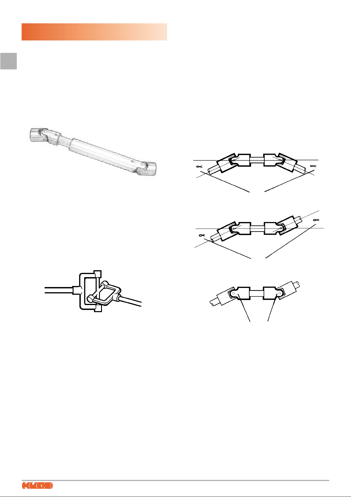
Constant velocity output can be restored by using a double
joint or by connecting two single joints back to back. Two rules
must be observed:
1. The operating angle must be the same at the input end as at
the output end (Figs. 1 & 2).
2. When connecting two single joints, they must be orientated
so that the inboard lugs are in line (Fig. 3).
Under these conditions the fluctuations in the first joint will for
all practical purposes be cancelled out by the complementary
fluctuations in the second.
These
angles must
be equal
Inboard
lugs
in line
Fig 1
These
angles must
be equal
Fig 2
Fig 3
Principle of
Hookes joint
General purpose
telescopic
drive shaft
7
Fax: +44 (0)1992 509890
UNIVERSAL JOINTS
2
®
application
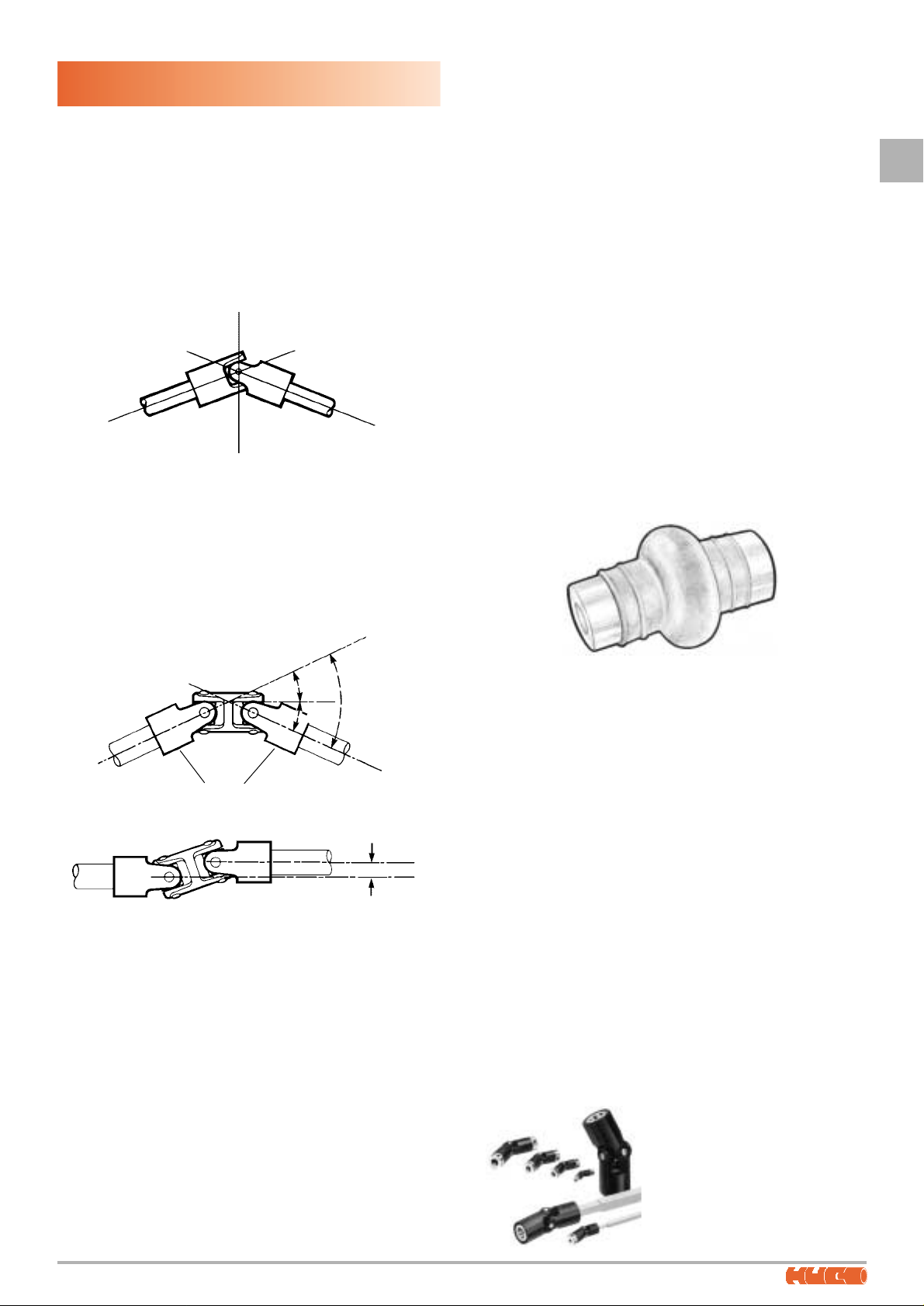
Universal joints are typically used to transmit positive rotation
through intentional offsets where the power source is some way
from the load. It is important to note that a U/J is essentially a
pivot and that it cannot accommodate any parallel displacement
between shafts if used singly. Moreover, the installation must
allow for some adjustment when mounting the joint so that the
shaft centre lines can be made to converge at the fulcrum of the
joint. This is essential if the joint is to function correctly and not
impose excessive radial loads on adjacent bearings.
Most applications however, demand a pair of U/J’s. This yields
several advantages including constant velocity output, a less
critical installation procedure, a shared operating angle (each joint
works at 50% of the total), and the ability to drive through laterally
displaced shafts. A pair of joints can comprise a drive shaft with a
U/J at each end or a double U/J for close coupled applications. A
double U/J offers greater misalignment compensation than a
misalignment coupler and runs at higher efficiency. For a given
torque rating however, it is usually significantly longer.
Telescopic drive shafts with a single U/J fitted at each end are
used to power mechanisms that move in relation to the power
source. The most common example is the drive shaft
connecting the gearbox to the rear axle on a road vehicle.
Another is the power take-off fitted at the rear of a tractor to
power-up ancillaries towed behind it. There are many more
applications in machine tools, packaging machinery and the
like. As the driven mechanism moves, the distance between the
U/J centres changes and since U/J’s cannot accommodate end
movement, a telescoping facility is built into the drive shafts.
Typically, this takes the form of a splined shaft with matching
broached tube. For lightly loaded or less critical applications,
nesting tubes cut from square material are adequate for the
purpose. It should be noted that although a pair of U/J’s
connected by a drive shaft and correctly set up will produce a
constant velocity output, the connecting shaft turns in
sympathy with the output of the first joint and is therefore
subject to the fluctuations governed by the working angle of the
first joint.
selection
U/J’s are selected for size on the basis of the torque to be
transmitted, the speed of rotation and the operating angle.
These variables give rise to a performance chart on which the
values can be read off and a suitable joint selected. Factors
relating to the nature of the power source or load are
sometimes applied. A single cylinder internal combustion
engine for example is more punishing to the transmission than
an electric motor. An even load is less onerous than an
intermittent one.
In principle, a U/J works harder as the operating angle
increases. The larger the operating angle, the lower the torque
or the speed at which it can be transmitted, or both.
In selecting the best type of universal joint for a given
application, the intended duty and life requirement are the
determining factors. High speeds and/or operating angles are
best handled by U/J’s fitted with roller bearings. These are
lubricated for life but it is nevertheless a good plan to protect
the moving surfaces with a gaiter which prevents the ingress of dust,
moisture and other foreign matter. Roller bearing joints are generally
specified where sustained rotational speeds exceed 1200/1500 rpm.
The most commonly specified joints are those fitted with plain
bearings. These are better at withstanding shock loads and are
adequate for speeds up to 1200/1500 rpm. Journals and
bearings are usually heat treated then ground and honed
respectively. On larger U/J’s , the bearing may be manufactured
separately and pressed into the parent metal before assembly.
To ensure an adequate service life, U/J’s should be regularly
lubricated. Where this is difficult due to inaccessibility, gaiters
will retain the lubricant and afford protection in aggressive
environments. For low speed or manual operation only, an
‘economy series’ joint may be adequate. These are
manufactured to looser tolerances and dispense with the
hardening, grinding and honing of bearings.
Lastly, U/J’s manufactured in plastics combined with nonferrous metals offer economy plus a set of properties not found
in steel joints. Foremost among these are their light weight,
resistance to corrosion electrical non-conductivity and freedom
from both lubrication and backlash. A supreme advantage of
the moulding technique is the cost-saving opportunities it
offers. Examples are the ease of producing non-circular bores
and the ability to integrate related components in the moulding
process, typically gear forms and toothed belt pulleys.
Compared with similarly sized steel joints, plastics U/J’s have a
significantly lower torque carrying capability.
Joint with protective
gaiter fitted
Correctly installed, the shaft
centre lines converge at the
fulcrum of the joint.
Lateral displacement
Each joint operates at
50% of total offset
5
0
%
5
0
%
100%
Huco-Pol U/J's and telescopic
drives are manufactured in acetal
and non-ferrous metals for costeffective use in light duty
applications. Bored Ø3mm to
16mm, the joints feature
backlash-free articulation.
Catalogue available on request.
2
STEEL UNIVERSAL JOINTS
8
Tel: +44 (0)1992 509888
®
features
Huco universal joints feature a comprehensive range of sizes
manufactured in good quality steels. Plain bearing and needle
roller types are available and either can be supplied with
square, hexagonal or keywayed bores to order. The joints are
also manufactured with quick release collars and in telescopic
form to order.
types TL & TS, plain bearings – 1200 rpm max
These joints feature hardened journals of generous proportions.
In joint sizes 13 – 60 (external diameter in mm) they are retained
in the forks and pivot in holes provided in the central core. A
large bearing surface is thus achieved which helps to reduce
wear and tear and prolongs the operational life of the joint.
By virtue of the increased wall thickness available in the larger
joints, pins fitted to sizes 70 – 100 are retained in the central
core and pivot in treated bushes housed in the fork ends.
type TR, needle roller bearings – 6000 rpm max
This series is intended for applications demanding high
rotational speeds (up to 6000 rpm) and large working angles
where operation is without benefit of periodic lubrication.
They are constructed with hardened and ground journals
pivoting between caged needle roller bearings housed in the
fork ends. Four bronze thrust rings interface between the
central core and the inner surfaces of the forks. These help to
achieve greater load capacities by minimising friction generated
by side loads.
Although the joints are pre-lubricated, rubber gaiters are
recommended as a protective measure in abrasive or damp
environments and to prevent ingress of foreign matter. Note that
good heat dissipation becomes important under conditions of
high working angles and high rotational speeds.
Type TR joints are suitable for all high speed applications or
where periodic lubrication is difficult, typically machine tools,
textile machines, multi-spindle drilling and tapping machines,
packaging machines, special purpose machines and
mechanical applications generally.
styles & sizes
U/J’s are produced in 17 sizes, identified by their outside diameter
in mm. All sizes are available in single and double form.
Style Outline Sizes
Any of these can be manufactured as a telescopic drive shaft.
The range of practical bore diameters corresponding with universal
joints is 5.00 – 60.00 mm.
Extended
unbored
series with
plain bearings
Standard
bored series
with plain
bearings
Standard
bored series
with needle
roller bearings
13 to 60 with 10 intermediate
sizes
13 to 100 with 15 intermediate
sizes
20 to 50 with 3 intermediate
sizes
2
STEEL UNIVERSAL JOINTS
type HS, plain bearings – 1500 rpm max
type HE
An economy series, similar to type HS but manufactured to a
lesser specification which omits the grinding, honing and heat
treatment operations. In consequence type HE is suitable only
for low speed transmissions and is intended for manual
operation or intermittent motorised applications.
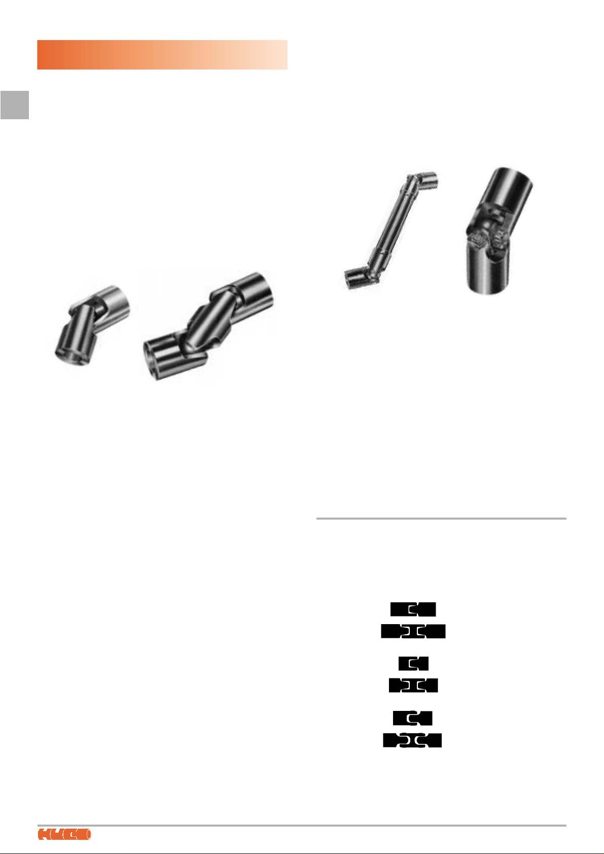
also available
The range also includes:
Joints with quick-release collars
Joints with needle roller bearings
Ball joints
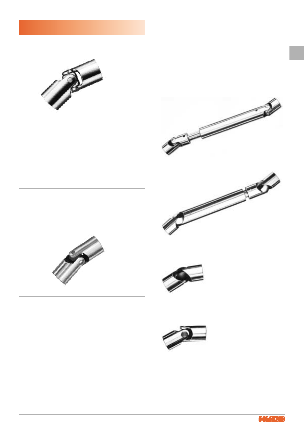
Any of these executions can be supplied as telescopic drive
shafts. Please contact Technical Sales for further information.
Telescopic drive shaft
with conventional joints.
Telescopic drive shaft
with ball joints.
Single ball joint.
Single joint fitted with needle
roller bearings.
The journals are machined
integral with the central block.
This series conforms to DIN 808 (alternative to DIN 7551) and
features conventional construction comprising 1 long and 2
short journals with mutual location within the hardened centre
block. Large bearings of equal diameter are machined into the
fork ends which are subsequently induction hardened and
honed to render a precision fit. A grinding operation on the
inner faces of the forks corrects any distortion to ensure
concentricity of bores.
The joints are suitable for all mechanical engineering
applications where the maximum speed of rotation does not
exceed 1500 rpm.
Fax: +44 (0)1992 509890
9
®
lubrication
Regular lubrication at intervals consistent with the duty cycle is
recommended in the interests of extending the life of the joint.
The joints should be adequately lubricated and the use of
rubber gaiters loaded with grease is recommended. They
protect against dust, damp and foreign matter and by ensuring
permanent lubrication of the sliding surfaces, maintain optimum
efficiency over a longer service life.
The gaiters are moulded in a special mix of synthetic rubber
which permits their use in temperatures from –20°C to 100°C.
They are resistant to oils, greases, many chemical agents, sea
water and tropical climates.
The joints are suitable for use in machine tools, textile
machines, agricultural equipment, multi-spindle drilling and
tapping machines and mechanical engineering applications
generally where the maximum speed of rotation does not
exceed 1200 rpm.
 Loading...