

Huck ERT1D, ERT2D, ERT4D, ERT1DL, ERT2DL Instruction Manual
Form HK 1039
04-16-2004
INSTRUCTION MANUAL
EBBERT RIVET TOOL MODELS
ERT1D, ERT2D, ERT4D,
ERT1DL
AND
ERT2DL


3
ERT D Series Tooling Alcoa Fastening Systems
SAFETY
This instruction manual must be read with particular
attention to the following safety guide lines, by any
person servicing or operating this tool.
1. Safety Glossary
WARNINGS - Must be understood
to avoid severe personal injury.
CAUTIONS - show conditions that will dam-
age equipment and or structure.
Notes - are reminders of required procedures.
Bold, Italic type and underlining -
empha-
sizes a specific instruction.
2. Huck equipment must be maintained in a safe
working condition at all times and inspected on a
regular basis for damage or wear. Any repair
should be done by a qualified repairman trained
on Huck procedures.
3. Repairman and Operator must read manual prior
to using equipment and understand any Warning
and Caution stickers/labels supplied with equipment before connecting equipment to any primary power supply. As applicable, each of the
sections in this manual have specific safety and
other information.
4. See MSDS Specifications before servicing the
tool. MSDS Specifications are available from
you Huck representative or on-line at
www.huck.com. Click on Installation Systems
Division.
5. When repairing or operating Huck installation
equipment, always wear approved eye protection. Where applicable, refer to ANSI Z87.1 1989
6. Disconnect primary power source before doing
maintenance on Huck equipment.
7. If any equipment shows signs of damage, wear,
or leakage, do not connect it to the primary
power supply.
8. Make sure proper power source is used at all
times.
9. Never remove any safety guards or pintail
deflector.
10. Never install a fastener in free air. Personal
injury from fastener ejecting may occur.
11. When using an offset nose always clear spent
pintail out of nose assembly before installing the
next fastener.
12. If there is a pinch point between trigger and
work piece use remote trigger. (Remote triggers are available for all tooling).
13. Do not abuse tool by dropping or using it as a
hammer. Never use hydraulic or air lines as a
handle. Reasonable care of installation tools by
operators is an important factor in maintaining
tool efficiency, eliminating downtime, and in preventing an accident which may cause severe
personal injury.
14. Never place hands between nose assembly and
work piece.
15. Tools with ejector rods should never be cycled
with out nose assembly installed.
16. When two piece lock bolts are being used
always make sure the collar orientation is correct. See fastener data sheet of correct positioning.
!
Product complies with requirements
set forth by the relevant European
directives.
Read manual prior to using
equipment.
Eye protection required while
using this equipment.
Hearing protection required while
using this equipment.

SAFETY
. . . . . . . . . . . . . . . . . . . . . . . . . . . . . . . . . . . . . . . . . . . . . . . . . . .3
GENERAL
INFORMATION
. . . . . . . . . . . . . . . . . . . . . . . . . . . . . . . . . . . . . .5
PRINCIPLE OF
OPERATION
. . . . . . . . . . . . . . . . . . . . . . . . . . . . . . . . . . . .5
TOOL SPECIFICATIONS
. . . . . . . . . . . . . . . . . . . . . . . . . . . . . . . . . . . . . .6-7
ERT1D & ERT2D SERIES SERVICE PROCEDURES
DISASSEMBLY
. . . . . . . . . . . . . . . . . . . . . . . . . . . . . . . . . . . . . . . . .8
REASSEMBLY
. . . . . . . . . . . . . . . . . . . . . . . . . . . . . . . . . . . . . . . . .9
ERT4D SERVICE PROCEDURES
DISASSEMBLY
. . . . . . . . . . . . . . . . . . . . . . . . . . . . . . . . . . . . . . . .10
REASSEMBLY
. . . . . . . . . . . . . . . . . . . . . . . . . . . . . . . . . . . . . . . . .11
RIVET TOOL HANDLE FUNCTION
. . . . . . . . . . . . . . . . . . . . . . . . . . . . . .12
AIR BLEEDING THE RIVET TOOL
. . . . . . . . . . . . . . . . . . . . . . . . . . . . . .12
A
SSEMBLY DRAWINGS AND PARTS LISTS
. . . . . . . . . . . . . . . . . . .13 - 16
T
ROUBLESHOOTING
. . . . . . . . . . . . . . . . . . . . . . . . . . . . . . . . . . . . . . . . .17
K
ITS AND ACCESSORIES
. . . . . . . . . . . . . . . . . . . . . . . . . . . . . . . . . . . . .18
4
ERT D Series Tooling Alcoa Fastening Systems
CONTENTS
This manual contains operating and service procedures for
the Ebbert Rivet Tool models ERT1D, ERT2D, ERT3D,
ERT4D, and their optional tool configurations. It is suggested that close attention be directed to the recommended
service procedures contained in this manual.
Specific instructions for each tool are given under that tool
model number heading. While they may appear to be similar, each tool contains parts not used on other models and
removal and replacement methods may vary.
5
ERT D Series Tooling Alcoa Fastening Systems
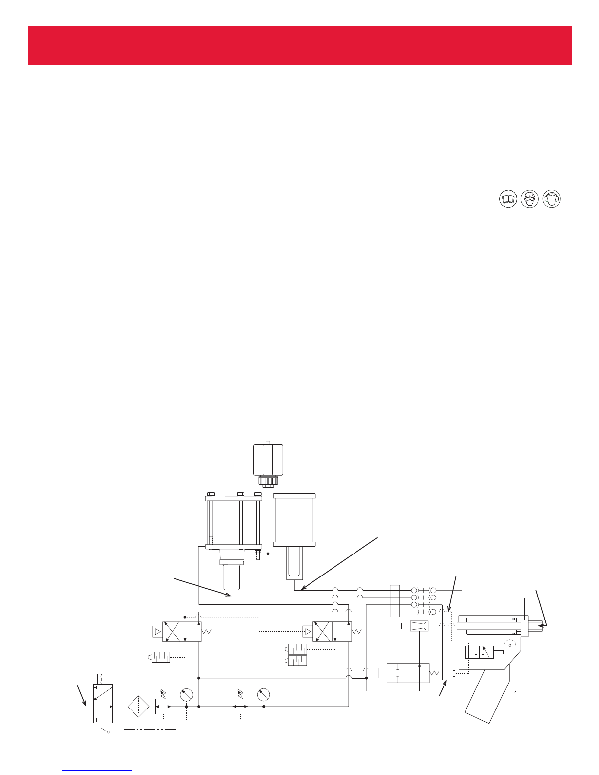
1.) Incoming non-oiled plant air is regulated at 90psi
through the Air Filter/Regulator to the Four-Way Valve,
and also through the Red Air Line to the valve in the
rivet tool handle. When air is initially applied to the
power unit, the Pull Stroke Power Booster is retracted
and the Return Stroke Power Booster is advanced.
2.) When the tool trigger is pulled, a trigger/plunger
unseats a valve ball and directs air from the tool handle
back through the Green Air Line to the Four-way Valve.
3.) The Four-way Valve is shifted, directing air pressure
through the Blue Air Line into the Pull Stroke Power
Booster and through the Red Air Line to the Exhaust
Valve of the Return Stroke Power Booster.
4.) As the Power Boosters air/hydraulic pistons advance,
hydraulic fluid is forced through the black Pull Stroke
Hydraulic Line into the tool, forcing the tool to retract.
This delivers the necessary force to install the fastener
and break the pintail.
5.) At the same time, the Four-Way Valve supplies air to
the Return Stroke Power Booster, forcing it to the
returned position.
6.) When the trigger is released, the Four-way Valve shifts
to its normal position. The normally open outlet of the
Four-Way Valve (labeled CYL1) directs 90psi pushing
both Power Booster air pistons to their original positions. The cycle is now completed. (In the EPS2V and
EPS2VL, the pintail would then travel through the pintail
collection tube from the tool into the Pintail Collection
Box.)
GENERAL INFORMATION
PRINCIPLE OF OPERATION
Non-Oiled
Plant Air
PULL
STROKE
Power
Booster
Pull Stroke Hydraulic
Pressure 4,000 PSI
Exhaust
Valve
90
PSI
Hydraulic
Fluid
Reservoir
25
PSI
RETURN
STROKE
Power
Booster
Return Stroke Hydraulic
Pressure 562 PSI
Green Line
Vacuum
Red Line
6
ERT D Series Tooling Alcoa Fastening Systems
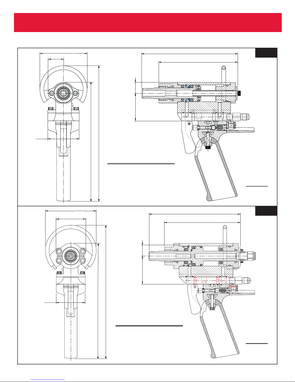
INCHES
mm
ERT1D, ERT1DL
Weight: ERT1D: 2.13 lbs.
ERT1DL: 1.63 lbs
Stroke: 15/16”
Rated Pull Force: 2,062 lbs.
Fastener Sizes: 3/32” through 3/16”
INCHES
mm
ERT2D, ERT2DL
Weight: ERT2D: 2.92 lbs.
ERT2DL: 2.36 lbs
Stroke: 1-1/32”
Rated Pull Force: 4,454 lbs.
Fastener Sizes: 1/8” through 1/4”
TOOL SPECIFICATIONS
Fig. 1
Fig. 1A
2.00
50.8
.97
24.6
3.00
76.2
8.60
218.4
7.54
191.5
(ERT1D only)
6.09
154.7
.69
17.5
2.44
62.0
(ERT1D only)
5.02
127.4
2.00
50.8
2.05
52.0
3.50
88.9
9.16
232.8
7.91
201.0
(ERT2D only)
6.31
160.3
.88
22.2
1.94
49.2
(ERT2D only)
5.23
132.9
 Loading...