

Page 1
Form HK 1039
04-16-2004
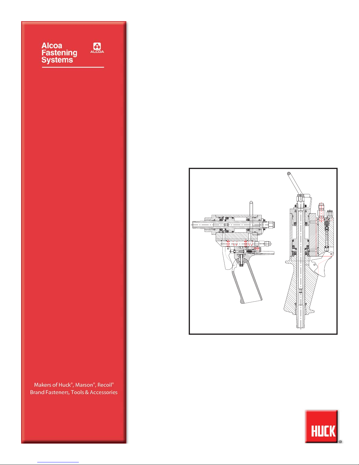
INSTRUCTION MANUAL
EBBERT RIVET TOOL MODELS
ERT1D, ERT2D, ERT4D,
ERT1DL
AND
ERT2DL
Page 2

Page 3
3
ERT D Series Tooling Alcoa Fastening Systems
SAFETY
This instruction manual must be read with particular
attention to the following safety guide lines, by any
person servicing or operating this tool.
1. Safety Glossary
WARNINGS - Must be understood
to avoid severe personal injury.
CAUTIONS - show conditions that will dam-
age equipment and or structure.
Notes - are reminders of required procedures.
Bold, Italic type and underlining -
empha-
sizes a specific instruction.
2. Huck equipment must be maintained in a safe
working condition at all times and inspected on a
regular basis for damage or wear. Any repair
should be done by a qualified repairman trained
on Huck procedures.
3. Repairman and Operator must read manual prior
to using equipment and understand any Warning
and Caution stickers/labels supplied with equipment before connecting equipment to any primary power supply. As applicable, each of the
sections in this manual have specific safety and
other information.
4. See MSDS Specifications before servicing the
tool. MSDS Specifications are available from
you Huck representative or on-line at
www.huck.com. Click on Installation Systems
Division.
5. When repairing or operating Huck installation
equipment, always wear approved eye protection. Where applicable, refer to ANSI Z87.1 1989
6. Disconnect primary power source before doing
maintenance on Huck equipment.
7. If any equipment shows signs of damage, wear,
or leakage, do not connect it to the primary
power supply.
8. Make sure proper power source is used at all
times.
9. Never remove any safety guards or pintail
deflector.
10. Never install a fastener in free air. Personal
injury from fastener ejecting may occur.
11. When using an offset nose always clear spent
pintail out of nose assembly before installing the
next fastener.
12. If there is a pinch point between trigger and
work piece use remote trigger. (Remote triggers are available for all tooling).
13. Do not abuse tool by dropping or using it as a
hammer. Never use hydraulic or air lines as a
handle. Reasonable care of installation tools by
operators is an important factor in maintaining
tool efficiency, eliminating downtime, and in preventing an accident which may cause severe
personal injury.
14. Never place hands between nose assembly and
work piece.
15. Tools with ejector rods should never be cycled
with out nose assembly installed.
16. When two piece lock bolts are being used
always make sure the collar orientation is correct. See fastener data sheet of correct positioning.
!
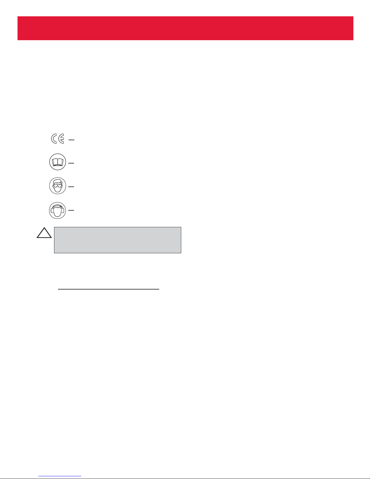
Product complies with requirements
set forth by the relevant European
directives.
Read manual prior to using
equipment.
Eye protection required while
using this equipment.
Hearing protection required while
using this equipment.
Page 4

SAFETY
. . . . . . . . . . . . . . . . . . . . . . . . . . . . . . . . . . . . . . . . . . . . . . . . . . .3
GENERAL
INFORMATION
. . . . . . . . . . . . . . . . . . . . . . . . . . . . . . . . . . . . . .5
PRINCIPLE OF
OPERATION
. . . . . . . . . . . . . . . . . . . . . . . . . . . . . . . . . . . .5
TOOL SPECIFICATIONS
. . . . . . . . . . . . . . . . . . . . . . . . . . . . . . . . . . . . . .6-7
ERT1D & ERT2D SERIES SERVICE PROCEDURES
DISASSEMBLY
. . . . . . . . . . . . . . . . . . . . . . . . . . . . . . . . . . . . . . . . .8
REASSEMBLY
. . . . . . . . . . . . . . . . . . . . . . . . . . . . . . . . . . . . . . . . .9
ERT4D SERVICE PROCEDURES
DISASSEMBLY
. . . . . . . . . . . . . . . . . . . . . . . . . . . . . . . . . . . . . . . .10
REASSEMBLY
. . . . . . . . . . . . . . . . . . . . . . . . . . . . . . . . . . . . . . . . .11
RIVET TOOL HANDLE FUNCTION
. . . . . . . . . . . . . . . . . . . . . . . . . . . . . .12
AIR BLEEDING THE RIVET TOOL
. . . . . . . . . . . . . . . . . . . . . . . . . . . . . .12
A
SSEMBLY DRAWINGS AND PARTS LISTS
. . . . . . . . . . . . . . . . . . .13 - 16
T
ROUBLESHOOTING
. . . . . . . . . . . . . . . . . . . . . . . . . . . . . . . . . . . . . . . . .17
K
ITS AND ACCESSORIES
. . . . . . . . . . . . . . . . . . . . . . . . . . . . . . . . . . . . .18
4
ERT D Series Tooling Alcoa Fastening Systems
CONTENTS
Page 5
This manual contains operating and service procedures for
the Ebbert Rivet Tool models ERT1D, ERT2D, ERT3D,
ERT4D, and their optional tool configurations. It is suggested that close attention be directed to the recommended
service procedures contained in this manual.
Specific instructions for each tool are given under that tool
model number heading. While they may appear to be similar, each tool contains parts not used on other models and
removal and replacement methods may vary.
5
ERT D Series Tooling Alcoa Fastening Systems
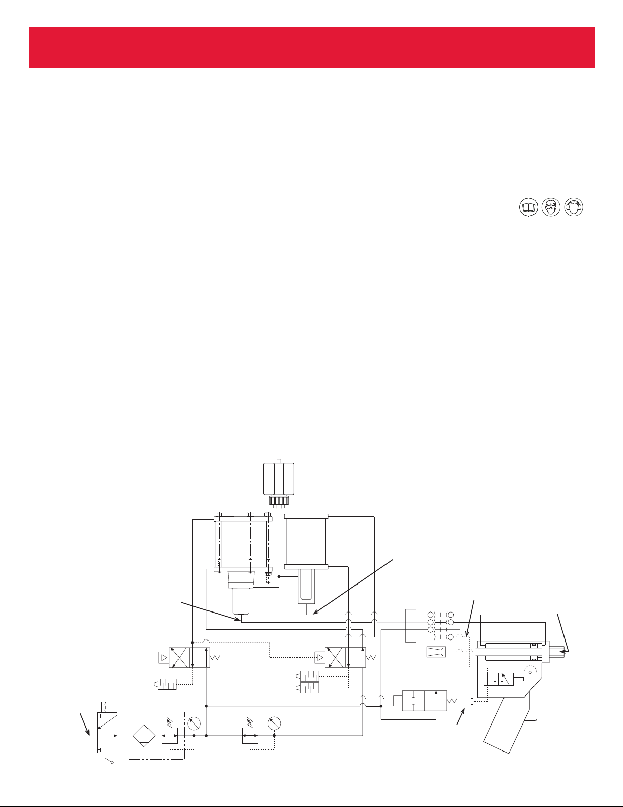
1.) Incoming non-oiled plant air is regulated at 90psi
through the Air Filter/Regulator to the Four-Way Valve,
and also through the Red Air Line to the valve in the
rivet tool handle. When air is initially applied to the
power unit, the Pull Stroke Power Booster is retracted
and the Return Stroke Power Booster is advanced.
2.) When the tool trigger is pulled, a trigger/plunger
unseats a valve ball and directs air from the tool handle
back through the Green Air Line to the Four-way Valve.
3.) The Four-way Valve is shifted, directing air pressure
through the Blue Air Line into the Pull Stroke Power
Booster and through the Red Air Line to the Exhaust
Valve of the Return Stroke Power Booster.
4.) As the Power Boosters air/hydraulic pistons advance,
hydraulic fluid is forced through the black Pull Stroke
Hydraulic Line into the tool, forcing the tool to retract.
This delivers the necessary force to install the fastener
and break the pintail.
5.) At the same time, the Four-Way Valve supplies air to
the Return Stroke Power Booster, forcing it to the
returned position.
6.) When the trigger is released, the Four-way Valve shifts
to its normal position. The normally open outlet of the
Four-Way Valve (labeled CYL1) directs 90psi pushing
both Power Booster air pistons to their original positions. The cycle is now completed. (In the EPS2V and
EPS2VL, the pintail would then travel through the pintail
collection tube from the tool into the Pintail Collection
Box.)
GENERAL INFORMATION
PRINCIPLE OF OPERATION
Non-Oiled
Plant Air
PULL
STROKE
Power
Booster
Pull Stroke Hydraulic
Pressure 4,000 PSI
Exhaust
Valve
90
PSI
Hydraulic
Fluid
Reservoir
25
PSI
RETURN
STROKE
Power
Booster
Return Stroke Hydraulic
Pressure 562 PSI
Green Line
Vacuum
Red Line
Page 6
6
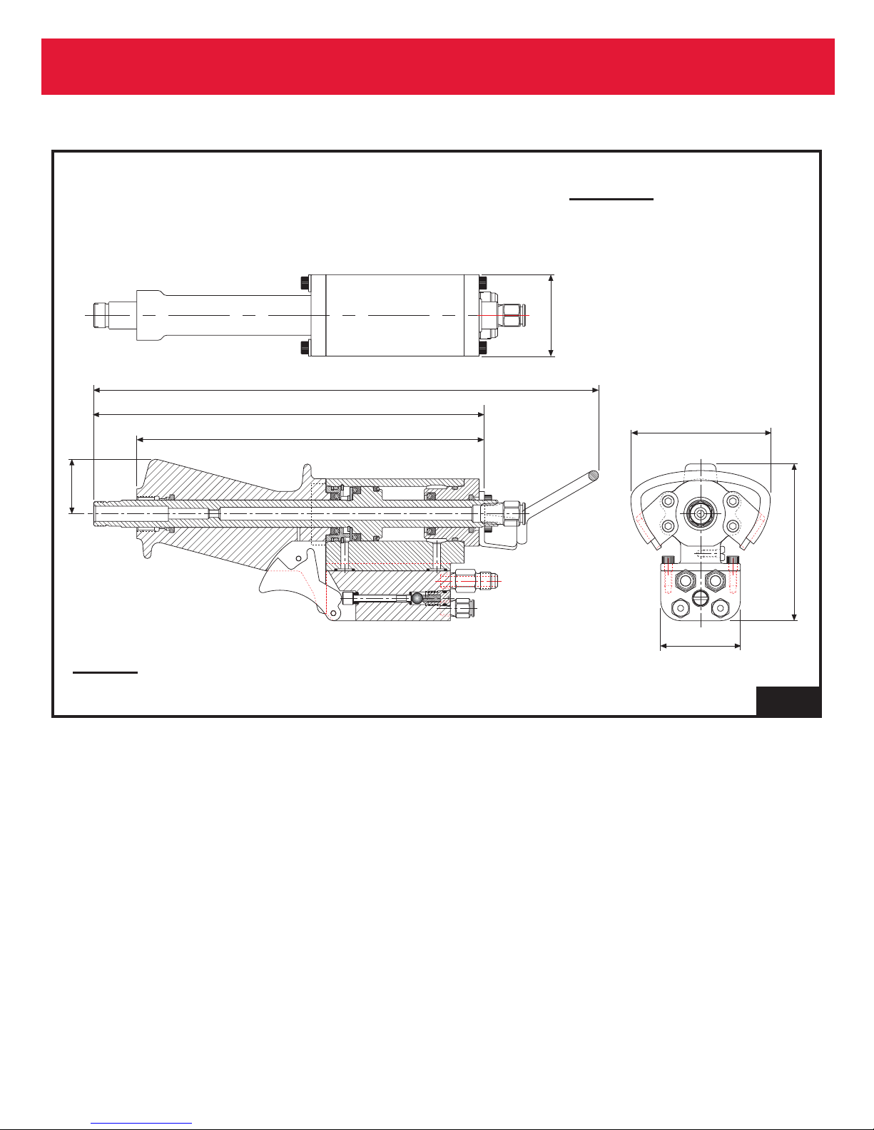
ERT D Series Tooling Alcoa Fastening Systems
INCHES
mm
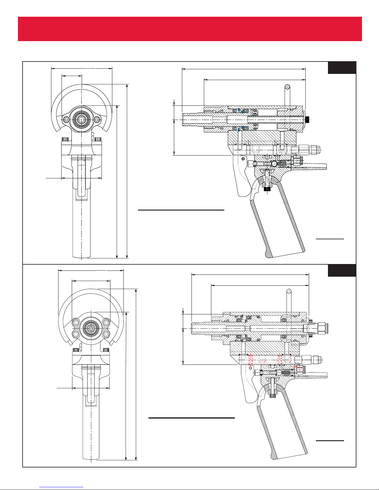
ERT1D, ERT1DL
Weight: ERT1D: 2.13 lbs.
ERT1DL: 1.63 lbs
Stroke: 15/16”
Rated Pull Force: 2,062 lbs.
Fastener Sizes: 3/32” through 3/16”
INCHES
mm
ERT2D, ERT2DL
Weight: ERT2D: 2.92 lbs.
ERT2DL: 2.36 lbs
Stroke: 1-1/32”
Rated Pull Force: 4,454 lbs.
Fastener Sizes: 1/8” through 1/4”
TOOL SPECIFICATIONS
Fig. 1
Fig. 1A
2.00
50.8
.97
24.6
3.00
76.2
8.60
218.4
7.54
191.5
(ERT1D only)
6.09
154.7
.69
17.5
2.44
62.0
(ERT1D only)
5.02
127.4
2.00
50.8
2.05
52.0
3.50
88.9
9.16
232.8
7.91
201.0
(ERT2D only)
6.31
160.3
.88
22.2
1.94
49.2
(ERT2D only)
5.23
132.9
Page 7
7
ERT D Series Tooling Alcoa Fastening Systems
INCHES
mm
ERT4D
Weight: 3.89 lbs.
Stroke: 1-1/32”
Rated Pull Force: 4,454 lbs.
Fastener Sizes: 1/8” through 1/4”
TOOL SPECIFICATIONS (CONTINUED)
Fig. 1B
2.05
52.0
12.67
9.81
249.1
8.73
221.7
321.9
3.50
88.9
1.37
34.7
2.00
50.8
3.94
100.0
Page 8
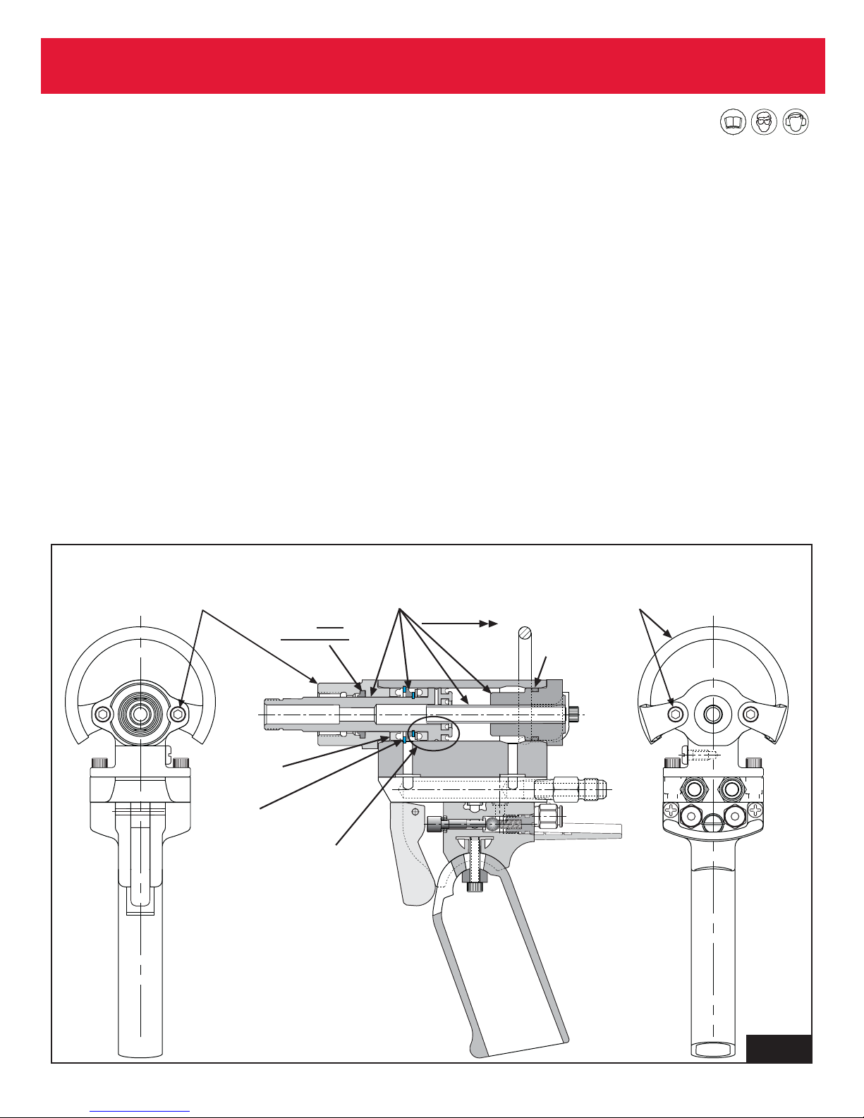
Disassembly of ERT1D & ERT2D
(Figure 2)
1. Unscrew the two Socket Head Screws for ERT1D or
four screws for ERT2D which secure the Piston Rod
Guide to the front of the tool, and remove the Piston
Rod Guide.
2. Loosen the Hose Clamp/Sleeve at the rear of the tool,
and pull it back far enough to allow clearance for the
removal of the End Cap. From the rear of the tool,
remove the two Socket Head Screws (ERT1D) or four
screws (ERT2D) and the Support Loop Assembly.
3. To remove the End Cap/Guide Tube Assembly, Piston
and Piston Forward Stop, push the Piston toward the
rear of the Cylinder.
4. Remove the remaining Seal from the front of the
Cylinder.
5. The Cylinder is now stripped of parts except the
Retaining Ring . For normal tool service it is not necessary to remove this Retaining Ring. If it is removed,
when replacing, be sure to relocate the retaining ring
ears at the bottom of the Cylinder, allowing clearance
for the hydraulic inlet port.
6.
ERT1D
Remove the Retaining Ring, Piston Forward Stop,
Piston Seal Retainer , and all Seals from the Piston, and
the Piston Rod Wiper from the Piston Rod Guide.
ERT2D
Remove the Retaining Ring, Front Seal Retainer and all
Seals from the Piston, and the O-ring, Back-up Ring,
Seal, and Piston Rod Wiper from the Piston Rod Guide.
NOTE: Whenever servicing the tool to this extent,
the Piston Rod Wiper must be replaced with a new
one.
7. Remove the O-ring from the End Cap.
8. Clean the disassembled parts in cleaning solution.
8
ERT D Series Tooling Alcoa Fastening Systems
SERVICE PROCEDURES
Fig. 2
Step 3:
Step 1:
Socket Head Screws
and Piston Rod Guide
Step 6:
Piston Rod
Wiper
must
be replaced.
End Cap/Guide
Tube Assy, Piston,
& Piston Forward Stop
Step 2:
Socket Head Screws
and Support Loop
Push rearward
Assembly
Step 7:
Remove
this O-ring
Step 4:
Remove
this Seal
Step 5:
This Retaining
Ring may be
left in place.
Step 6:
Remove three
Seals, Piston
Forward Stop,
Piston Seal Retainer, and Retaining
Ring from Piston.
Page 9

Reassembly of ERT1D and ERT2D
1. When replacing seals, make sure they are correctly
positioned as shown on the tool assembly drawings in
this manual. Wipe all seals with a thin film of seal lubricant before reassembly.
2. It is important to inspect the cylinder wall to insure the
surface is free of any gouges or nicks that will damage
a new seal. Small nicks or gouges can normally be
removed using a fine crocus cloth.
3. After all seals, o-rings and back-up rings are replaced,
ERT1D
With the Piston Forward Stop placed on the Piston
shaft, insert the End Cap Assembly into the Piston, then
slide the complete assembly into the tool Cylinder.
ERT2D
Insert the End Cap Assembly into the Piston, then slide
the complete assembly into the tool Cylinder.
NOTE: Use caution when inserting this assembly
into the cylinder to keep the piston from "cocking"
in the cylinder and "nicking" the cylinder wall. This
could ultimately cause a seal edge to be cut.
Secure the End Cap and Support Loop Assembly with
two screws (ERT1D) or four screws (ERT2D).
4. At this point, reposition the tool in the vice with the open
front of the cylinder pointing straight up. You can choose
from two options for filling the tool with hydraulic fluid:
a) Gravity fill: Connect the hydraulic line to the power
unit and allow hydraulic fluid to flow from the higher
positioned reservoir into the tool cylinder until it is
level with the front Retaining Ring, then disconnect
the hydraulic line for installation of remaining components.
b) Optional fill: Using the Model 300509 Bleed Pump
Assembly, you can save time by pumping from the
hydraulic connector thru the line, filling the tool in
the same manner and to the same level as above.
5.
ERT2D
Replace the Front Seal Retainer by positioning the
cutout section so it will clear the two ears of the
Retaining Ring when it is dropped into place. If the
retainer does not lay flat, tap it gently with a screwdriver until it assumes a flat position.
6. Slide the hydraulic seal down over the piston threads
and wrench flats carefully to prevent "nicking" the seal
edges.
ERT1D
Insert the Piston Rod Guide and Wiper assembly , pushing the Hydraulic Seal down into the Cylinder. Secure
the Piston Rod Guide with two screws. Torque the
screws at both ends of the tool to 12-15 ft/lbs.
ERT2D
It is not necessary to push the seal all of the way into
the Cylinder. It will assume it s position in the Piston Rod
Guide when the guide is next installed and secured with
the two Bearing Plates and four Screws. Torque the
screws at both ends of the tool to 60-80 in./lbs.
8. This method of refilling the tool with hydraulic fluid
relieves any further requirement for bleeding air. The
tool can now be connected to the power unit and be test
cycled. The pulling head assembly can now be
installed.
9
ERT D Series Tooling Alcoa Fastening Systems
SERVICE PROCEDURES (CONT.)
Page 10
10
ERT D Series Tooling Alcoa Fastening Systems
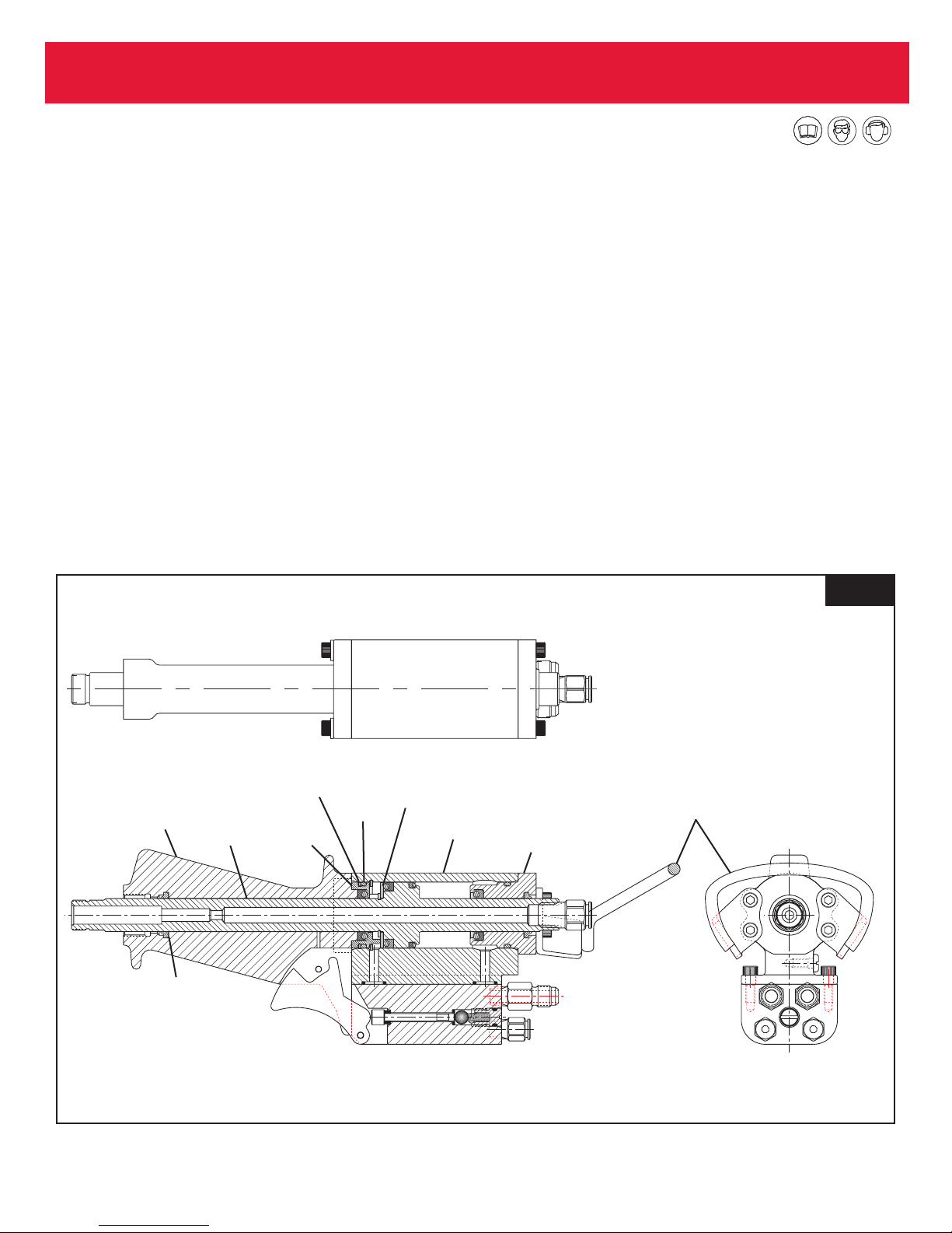
Disassembly of ERT4D (Figure 3)
1. Remove the Handle from the front of the tool.
2. Loosen the Hose Clamp/Sleeve at the rear of the tool,
and pull it back far enough to allow clearance for the
removal of the End Cap.
3. After removing the Support Loop Assembly, the Piston
and End Cap can be removed by pushing back on the
front of the Piston for removal through the back of the
tool.
4. Remove the O-Ring from the End Cap.
5. The Front Seal Retainer must be removed from the
front of the tool. This retainer is a snug fit and generally
requires a soft hammer blow to the end of a brass dowel
held against the Seal Retainer.
6. The Cylinder is now stripped of parts except the
Retaining Ring . For normal tool service it is not necessary to remove this Retaining Ring. If it is removed,
when replacing, be sure to relocate the retaining ring
ears at the bottom of the Cylinder, allowing clearance
for the hydraulic inlet port.
7. Remove the Retaining Ring, Piston Seal Retainer and
all Seals from the Piston, and the O-ring, Back-up Ring,
and hydraulic Seal from the Front Seal Retainer.
NOTE: Whenever servicing the tool to this extent,
the Piston Rod Wiper must be replaced with a new
one.
8. Clean the disassembled parts in cleaning solution.
SERVICE PROCEDURES
(CONT.)
Fig. 3
Back-up
Ring
Handle
Piston
Piston
Rod
Wiper
Front
Seal
Retainer
O-Ring
Piston
Seal
Retainer
Cylinder
End Cap/
Guide Tube
Assembly
Support Loop
Assembly
Page 11

Reassembly of ERT4D
1. When replacing seals, make sure they are correctly
positioned as shown on the Tool Schematic. Wipe all
seals with a thin film of seal lubricant before reassembly.
2. It is important to inspect the cylinder wall to insure the
surface is free of any gouges or nicks that will damage
a new seal. Small nicks or gouges can normally be
removed using a fine crocus cloth.
3. After all seals, o-rings and backup rings are replaced,
insert the End Cap Assembly into the Piston, and insert
as a combination into the tool Cylinder.
NOTE: Use caution when inserting this assembly
into the cylinder to keep the piston from "cocking"
in the cylinder and "nicking" the cylinder wall. This
could ultimately cause a seal edge to be cut.
Secure the End Cap and Support Loop Assembly with
four screws.
4. At this point, reposition the tool in the vice with the open
front of the cylinder pointing straight up. You can choose
from two options for filling the tool with hydraulic fluid:
a) Gravity fill: Connect the hydraulic line to the power
unit and allow hydraulic fluid to flow from the higher
positioned reservoir into the tool cylinder until it is
level with the front Retaining Ring, then disconnect
the hydraulic line for installation of remaining com
ponents.
b) Optional fill: Using the Model 300509 Bleed Pump
Assembly, you can save time by pumping from the
hydraulic connector thru the line, filling the tool in
the same manner and to the same level as above.
5. Making sure the cutout section will clear the ears of the
Retaining Ring, slide the Front Seal Retainer down,
using care to get it positioned straight in the Cylinder.
The Retainer does not easily slide into the Cylinder; it
will be drawn into place later when the Handle is
secured.
6. Slide the hydraulic seal down over the piston threads
and wrench flats carefully to prevent "nicking" the seal
edges, and position it in the Front Seal Retainer.
Positioning this seal requires some effort to work it in.
Start it down on one side and slowly work it in until the
last small area may be assisted by using the flat side of
a common screwdriver.
7. Install the Handle and Piston Rod Wiper down over the
Piston and into contact with the Front Seal Retainer.
While doing this, hold the trigger in position to allow it to
drop behind the lock-in pin. Install the four Screws with
Bearing Plates with equal pressure to draw the Handle
and Seal Retainer into position in the Cylinder. Torque
the screws at both ends of the tool to 60-80 in./lbs.
8. Air Bleed the tool if necessary. The tool can now be connected to the power unit and be test cycled. The pulling
head assembly can now be installed.
11
ERT D Series Tooling Alcoa Fastening Systems
SERVICE PROCEDURES (CONT.)
Page 12
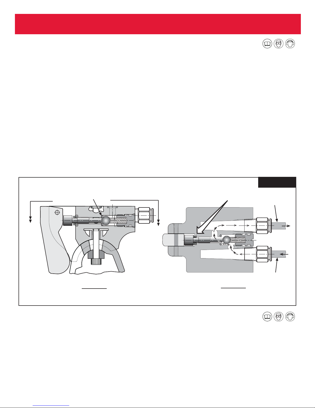
The rivet tool handle contains the air valve mechanism
which, when actuated, initiates the rivet station cycle.
Figure 4A depicts the valve components in the “at rest”
position. The steel ball is sealing air pressure within the red
air line chamber.
Figure 4B shows how the double Quad Rings function to
seal the forward section of the chamber when the Trigger is
depressed, directing air pressure through the green air line
back to the four-way valve.
After prolonged use, the Quad Rings will wear down resulting in a poor seal when the trigger is actuated. This can slow
down the cycle time of the tool due to the rivet tool operator
holding the trigger in a tighter position when setting the rivet.
It is easy to remedy the problem. Remove the trigger pin,
trigger, and valve plunger for Quad Ring replacement.
On models ERT1D and ERT2D the handle is adjustable
through a 20 degree arc. This patented design allows relief
to the wrist when work heights are high or low to the operator’s normal body position.
Each tool is provided with a 5/32” hex ball driver for the handle adjustment. By loosening the socket head screw located inside the handle, the handle can be moved into the
desired position and locked into that location with the hex
ball driver.
In some operations requiring excessive loads on the handle,
it is suggested that the clamp block be reversed, placing the
flat surface into contact with the handle for higher locking
force.
NOTE: Make sure the trigger is square to the handle
slot and moves freely after tightening the clamp block.
12
ERT D Series Tooling Alcoa Fastening Systems
RIVET TOOL HANDLE FUNCTION
AIR BLEEDING THE RIVET TOOL
Disconnect the Rivet Tool from the Power Unit end.
To Bleed PULL Stroke side of Tool:
Attach Bleed Pump 300509 to the black hydraulic hose on
the rivet tool. Remove the front Bleed Screw from the tool.
Pump the Bleed Pump until no more bubbles appear out of
the bleed port of the tool. Replace the Bleed Screw.
To Bleed RETURN Stroke side of Tool:
Attach Bleed Pump 300509 to the orange hose on the rivet
tool. Remove the rear Bleed Screw from the tool. Pump the
Bleed Pump until no more bubbles appear out of the bleed
port of the tool. Replace the Bleed Screw.
Fig. 4A & B
Steel Ball seats against
O-ring, sealing air pressure
within the red air line chamber
Quad Rings
compressed
Green Air Line
See
Figure B
Figure A
Valve Components at Rest
See
Figure B
Figure B
Air Flow at Trigger Activation
Red Air Line
Page 13
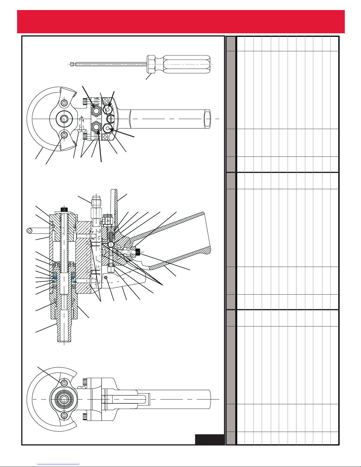
13
ERT D Series Tooling Alcoa Fastening Systems
Fig. 5
Item Part No. Description Qty. Item Part No. Description Qty. Item Part No. Description Qty.
1 300048 Piston 1
2 508010 Piston Rod Wiper 1
3 507666 Seal 2
4 500944 Retaining Ring 1
5 300143 Piston Forward Stop 1
6 500650 Retaining Ring 1
7 300123 Seal Retainer 1
8 507670 Seal 1
9 507669 Seal 1
10 300012 Cylinder 1
11 500815 O-Ring 1
12 300140 End Cap & Guide Tube Assy 1
13 505475 Hose Adapter 2
14 300254 Guard 1
15 500776 O-Ring 1
16 507552 Spring 1
17 300039 Handle Bracket 1
18 507664 Ball 1
19 300108 Clamp Block 1
20 500064 Socket Head Screw 1
21 300257 Handle 1
22 500774 O-Ring 3
23 504350 Quad Ring 2
24 300133 Valve Plunger 1
25 300253 Trigger 1
26 500623 Pin 1
27 504551 O-Ring 2
28 300014 Piston Rod Guide 1
29 500072 Socket Head Screw 4
30 300109 Support Loop Assy 1
31 507660 Bleed Screw 1
32 500061 Socket Head Screw 4
33 300164 Manifold Block 1
34 507661 Self-Tapping Screw 2
35 507662 Male Connector 2
36 300059 Seal Plug 1
Pull
Stroke
Hose
(Black)
36
Green
Air
Line
507659 Hex
Ball Driver
(Shipped with
Red
Air
tool)
Line
30
12
11
10
35
7
61
34 89
2
29 (2)
Torque
31 (2)
screws to
12-15 ft/lbs.
13
32 (8)
33
Return
28
Stroke
27
35 (2)
34 (2)
Hose (Orange)
14
15
25
26
16
24
17
18
22
23 (2)
19
21
20
29 (2)
Torque
screws to
12-15 ft/lbs.
ERT1D
Page 14

14
ERT D Series Tooling Alcoa Fastening Systems
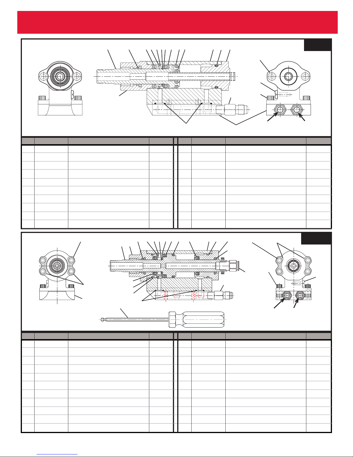
Fig. 6
Item Part No. Description Qty. Item Part No. Description Qty. Item Part No. Description Qty.
1 300053 Piston 1
2 300025 Piston Rod Guide 1
3 508010 Piston Rod Wiper 2
4 300055 Front Seal Retainer 1
5 500948 Retaining Ring 1
6 500650 Retaining Ring 1
7 300122 Piston Seal Retainer 1
8 507667 Seal 1
9 507668 Seal 1
10 507666 Seal 1
11 300006 Cylinder 1
12 500820 O-Ring 1
13 300030 End Cap 1
14 300293 Male Connector 1
15 505475 Hose Adapter 2
16 300254 Guard 1
17 500776 O-Ring 1
18 507552 Spring 1
19 300039 Handle Bracket 1
20 507664 Ball 1
21 300257 Handle 1
22 500064 Socket Head Screw 9
23 300108 Clamp Block 1
24 500774 O-Ring 3
25 504350 Quad Ring 2
26 300133 Valve Plunger 1
27 300253 Trigger 1
28 500623 Pin 1
29 504551 O-Ring 2
30 500820 O-Ring 1
31 507976 Back-up Ring 1
32 300165 Manifold Block 1
33 300064 Screw Bearing Plate 2
34 300114 Support Loop Assembly 1
35 500061 Socket Head Screw 8
36 507661 Self-Tapping Screw 2
37 507662 Male Connector 2
38 300059 Seal Plug 1
39 507660 Bleed Screw 2
40 507659 Hex Ball Driver 1
When tool is
used without
Hanger (34),
two additional
Screw Bearing
Plates (33) are
required here.
39 (2)
Pull Stroke
Hose (Black)
Green
Air Line
38
37 (2)
40
34
22 (4)
13
12
11
10
9
8
7
6
5
4
3
Torque
screws to
3
2
1
14
60-80 in/lbs
15 (2)
10
35 (8)
31
Return Stroke
30
Red
36 (2)
Hose (Orange)
16
17
28
29
27
Air Line
18
19
26
20
25 (2)
24
23
22
21
22 (4)
Torque
screws to
60-80 in/lbs
33
32
ERT2D
Page 15
15
ERT D Series Tooling Alcoa Fastening Systems
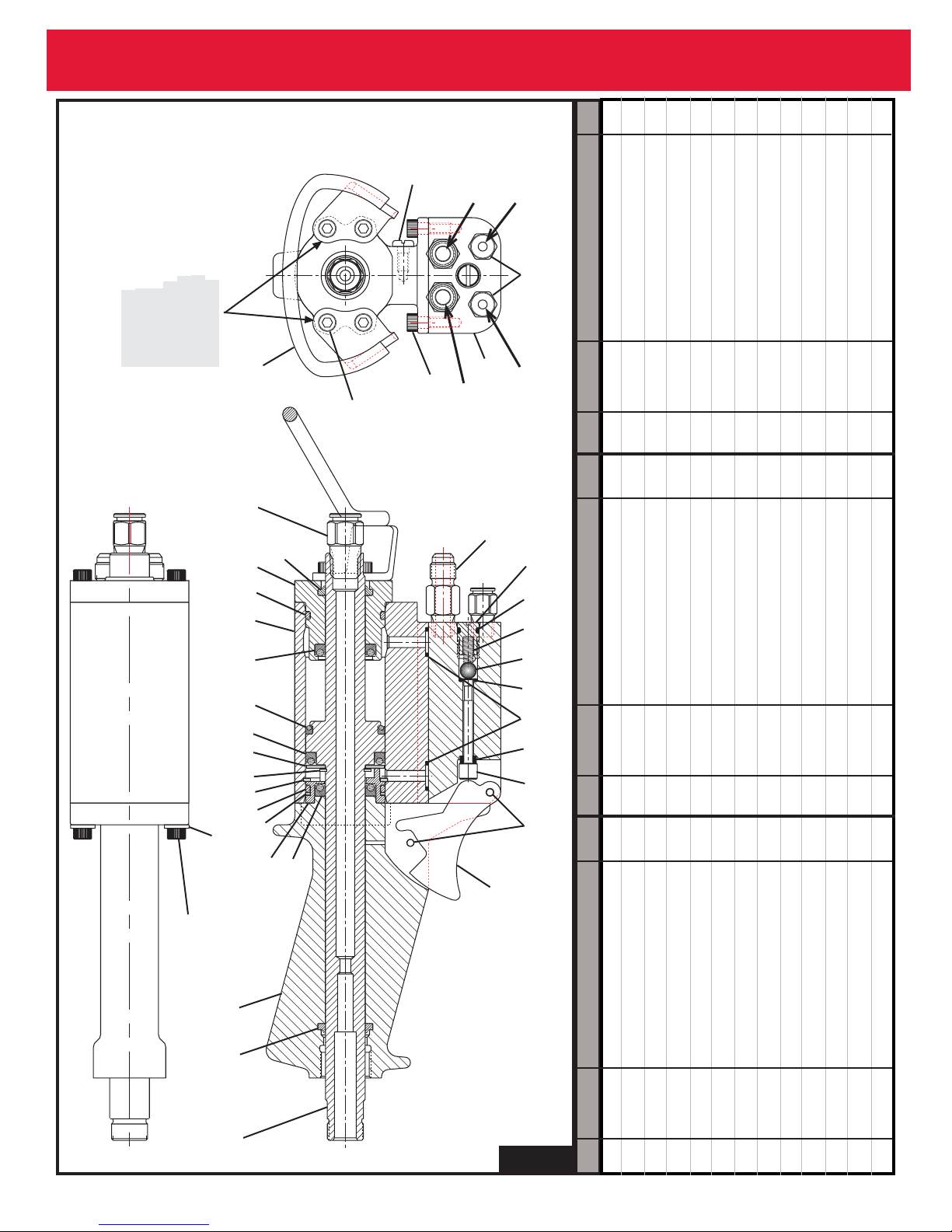
Fig. 8
Item Part No. Description Qty. Item Part No. Description Qty.
1 300053 Piston 1
2 300025 Piston Rod Guide 1
3 508010 Piston Rod Wiper 2
4 300055 Front Seal Retainer 1
5 500948 Retaining Ring 1
6 500650 Retaining Ring 1
7 300122 Piston Seal Retainer 1
8 507667 Seal 1
9 507668 Seal 1
10 507666 Seal 1
11 300006 Cylinder 1
12 500820 O-Ring 2
13 300030 End Cap 1
14 300293 Male Connector 1
15 505475 Hose Adapter 2
16 504551 O-Ring 2
17 507976 Back-up Ring 1
18 300165 Manifold Block 1
19 300064 Screw Bearing Plate 4
20 500064 Socket Head Screw 8
21 500061 Socket Head Screw 4
22 507660 Bleed Screw 2
Fig. 7
Item Part No. Description Qty. Item Part No. Description Qty.
1 300048 Piston 1
2 508010 Piston Rod Wiper 1
3 507666 Seal 2
4 500944 Retaining Ring 1
5 300143 Piston Forward Stop 1
6 500650 Retaining Ring 1
7 300123 Seal Retainer 1
8 507670 Seal 1
9 507669 Seal 1
10 300012 Cylinder 1
11 500815 O-Ring 1
12 300140 End Cap & Guide Tube Assy 1
13 505475 Hose Adapter 2
14 300164 Manifold Block 1
15 504551 O-Ring 2
16 300014 Piston Rod Guide 1
17 500072 Socket Head Screw 4
18 507660 Bleed Screw 2
19 500061 Socket Head Screw 4
20 507659 Hex Ball Driver (not shown) 1
11
12
13
14
Torque screws
to 12-15 ft/lbs.
18 (2)
19 (4)
Return Stroke
Hose (Orange)
1
16
2
3
ERT1DL
7
5
6
4
15 (2)
9
3
8
10
17 (4)
Pull Stroke
Hose (Black)
20 (4)
Torque
screws to
60-80 in/lbs
19
507659 Hex
Ball Driver
18
(Shipped with
tool)
3
5
6
4
2
1
10
17
12
16
7
9
8
10
11
12
13
3
15 (2)
20 (4)
Torque
screws to
60-80 in/lbs
14
Return Stroke
Hose (Orange)
19
21 (4)
Pull Stroke
Hose (Black)
ERT2DL
22
(2)
Page 16
16
ERT D Series Tooling Alcoa Fastening Systems
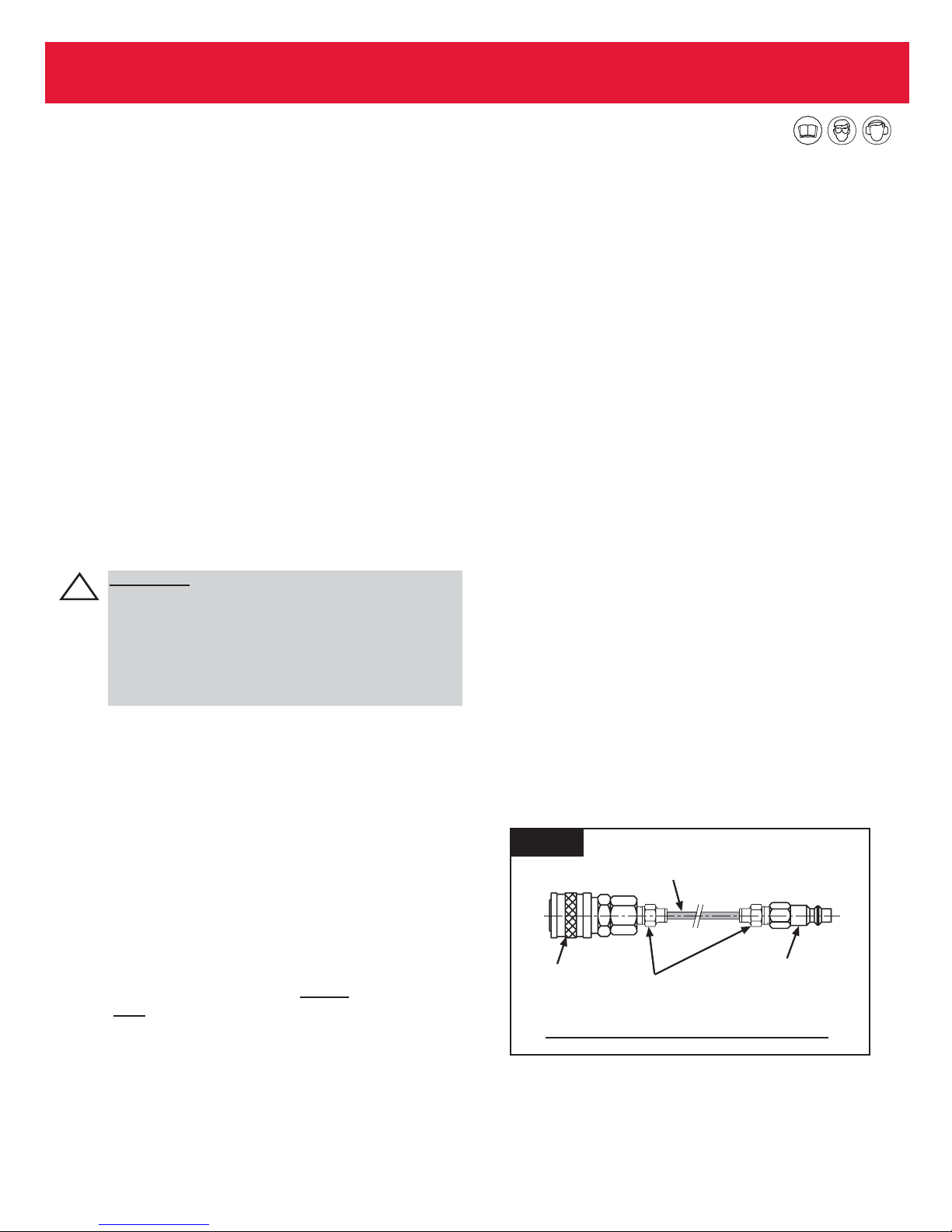
Fig. 9
Item Part No. Description Qty. Item Part No. Description Qty. Item Part No. Description Qty.
1 300054 Piston 1
2 508010 Piston Rod Wiper 1
3 300032 Handle 1
4 507666 Seal 2
5 300056 Front Seal Retainer 1
6 507976 Back-up Ring 1
7 500820 O-Ring 2
8 500948 Retaining Ring 1
9 500650 Retaining Ring 1
10 300122 Piston Seal Retainer 1
11 507667 Seal 1
12 507668 Seal 1
13 300007 Cylinder 1
14 300030 End Cap/Guide Tube Assy 1
15 300293 Male Connector 1
16 505475 Hose Adapter 1
17 300059 Seal Plug 1
18 500776 O-Ring 1
19 507552 Spring 1
20 507664 Ball 1
21 500774 O-Ring 3
22 504551 O-Ring 2
23 504350 Quad Ring 2
24 300146 Valve Plunger 1
25 500623 Pin 2
26 300255 Trigger 1
27 300064 Screw Bearing Plate 2
28 500064 Socket Head Screw 8
29 300126 Support Loop Assembly 1
30 500061 Socket Head Screw 4
31 300046 Manifold Block 1
32 507662 Male Connector 2
33 507660 Bleed Screw 1
33 (2)
Green
Air Line
Hose (Black)
32
31
Red
Air Line
When tool is
used without
Hanger (29),
two additional
Screw Bearing
Plates (27) are
required here.
29
Pull Stroke
30 (4)
27 (2)
15
14
7
13
4
12
11
10
9
8
28 (4)
Torque
screws to
60-80 in/lbs
Return Stroke
Hose (Orange)
16 (2)
2
17
18
19
20
21
22
23
24
7
6
5
4
25
28 (4)
Torque
screws to
60-80 in/lbs
3
2
1
26
ERT4D
Page 17
TROUBLESHOOTING
17
ERT D Series Tooling Alcoa Fastening Systems
Always check out the simplest possible cause of a malfunction first. For example, an air hose not connected. Then proceed logically, eliminating each possible cause until the
cause is located. Where possible, substitute known good
parts for suspected bad parts. Use TROUBLESHOOTING
CHART as an aid in locating and correcting malfunction.
1 Slow Tool Cycle:
a)Check air pressure and hydraulic pressure. Reference
Principle of Operation Schematic on page 5 of this
manual.
b) Incoming air line must be 3/8” ID minimum. If longer
that 20’, air line should increase to 1/2” ID.
2 Tool will not pull rivet:
a) Air in hydraulic system; requires bleeding.
A
IR BLEEDING THE POWER UNIT
Bleeding Pull Stroke Power Booster 300403
1. Turn air supply off. Connect Bleed Pump 300509
to male Hydraulic Fitting on Manifold.
2. Pump Bleed Pump until air bubbles in the Reservoir
disappear.
3. Remove Bleed Pump from Manifold before next
step. Otherwise Bleed Pump will be pressurized
and can cause possible damage to Bleed Pump
or injury to personnel.
Bleeding Return Stroke Power Booster 300400
1. Connect Jumper (Figure 10) to male and female air
fittings on Manifold.
2. Turn air supply on.
3. Connect Bleed Pump to female
hydraulic fitting
only.
4. Pump Bleed Pump until air bubbles in reservoir disappear.
5. Remove Bleed Pump from Manifold.
6. Remove Jumper. Bleed Pump and Jumper must
be removed in this order only. Otherwise Bleed
Pump will be pressurized and can cause possible damage to Bleed Pump or injury to personnel.
Air Bleeding Power Unit and Rivet Tool
Together
PULL STROKE
1. Remove red and green air lines connecting the tool
to the power unit from the Power Unit end (where
they connect to the Manifold).
2. Connect Bleed Pump and Bleed Port Hose to the
front Bleed Screw of the Tool.
3. Pump Bleed Pump until air bubbles in reservoir disappear.
4. Remove Bleed Pump from the Tool and replace
Bleed Screw.
RETURN STROKE
1. Remove red and green air lines connecting the tool
to the power unit from the Power Unit end (where
they connect to the Manifold), and connect
Jumper (Figure 10) to male and female air fittings
on Manifold.
2. Turn air supply on.
3. Connect Bleed Pump and Bleed Port Hose to the
rear Bleed Screw of the Tool.
4. Pump Bleed Pump until air bubbles in reservoir disappear.
5. Remove Bleed Pump from tool, and replace Bleed
Screw.
6. Remove Jumper. Bleed Pump and Jumper must
be removed in this order only. Otherwise Bleed
Pump will be pressurized and can cause possible damage to Bleed Pump or injury to personnel.
Fashion Jumper out of spare parts shown.
Fig. 10
WARNING: Be sure to disconnect your power
tool's air hose from the power unit when air
bleeding or filling the unit with hydraulic fluid.
This will prevent accidental actuation of the
power circuit which could cause pressurization
and damage to the Bleed Pump. NOTE: Do not
run reservoir empty!!
!
507675 or 507676
Green or Red Tubing
507678
Quick
Connect
507662
Connector
507677
Quick
Disconnect
Page 18

18
ERT D Series Tooling Alcoa Fastening Systems
S
ERVICE NOTES
:
KITS AND ACCESSORIES
Piston Assembly Bullet - 300072
Service Kit ERT1D, ERT1DL -300477
Service Kit ERT2D, ERT2DL -300478
Filler / Bleed Pump Assembly - 300509
Page 19

ERT D Series Tooling Alcoa Fastening Systems
LIMITED WARRANTIES
Tooling Warranty: Huck warrants that tooling and other
items (excluding fasteners, and hereinafter referred as
"other items") manufactured by Huck shall be free from
defects in workmanship and materials for a period of ninety (90) days from the date of original purchase.
Warranty on "non standard or custom manufactured
products": With regard to non-standard products or cus-
tom manufactured products to customer's specifications,
Huck warrants for a period of ninety (90) days from the
date of purchase that such products shall meet Buyer's
specifications, be free of defects in workmanship and
materials. Such warranty shall not be effective with
respect to non-standard or custom products manufactured
using buyer-supplied molds, material, tooling and fixtures
that are not in good condition or repair and suitable for
their intended purpose.
THERE ARE NO WARRANTIES WHICH EXTEND
BEYOND THE DESCRIPTION ON THE FACE HEREOF.
HUCK MAKES NO OTHER WARRANTIES AND
EXPRESSLY DISCLAIMS ANY OTHER WARRANTIES,
INCLUDING IMPLIED WARRANTIES AS TO MERCHANTABILITY OR AS TO THE FITNESS OF THE
TOOLING, OTHER ITEMS, NONSTANDARD OR CUSTOM MANUF ACTURED PRODUCTS FOR ANYPARTICULAR PURPOSE AND HUCK SHALL NOT BE LIABLE
FOR ANY LOSS OR DAMAGE, DIRECTLY OR INDIRECTLY, ARISING FROM THE USE OF SUCH TOOLING, OTHER ITEMS, NONSTANDARD OR CUSTOM
MANUFACTURED PRODUCTS OR BREACH OF WARRANTY OR FOR ANY CLAIM FOR INCIDENTAL OR
CONSEQUENTIAL DAMAGES.
Huck's sole liability and Buyer's exclusive remedy for any
breach of warranty shall be limited, at Huck's option, to
replacement or repair, at FOB Huck's plant, of Huck manufactured tooling, other items, nonstandard or custom
products found to be defective in specifications, workmanship and materials not otherwise the direct or indirect
cause of Buyer supplied molds, material, tooling or fixtures. Buyer shall give Huck written notice of claims for
defects within the ninety (90) day warranty period for tooling, other items, nonstandard or custom products
described above and Huck shall inspect products for which
such claim is made.
Tooling, Part(s) and Other Items not manufactured by
Huck.
HUCK MAKES NO WARRANTY WITH RESPECT TO
THE TOOLING, PART(S) OR OTHER ITEMS MANUFACTURED BY THIRD PARTIES. HUCK EXPRESSLY DISCLAIMS ANY WARRANTY EXPRESSED OR IMPLIED,
AS TO THE CONDITION, DESIGN, OPERATION, MER-
CHANTABILITY OR FITNESS FOR USE OF ANY TOOL,
PART(S), OR OTHER ITEMS THEREOF NOT MANUFACTURED BY HUCK. HUCK SHALL NOT BE LIABLE
FOR ANY LOSS OR DAMAGE, DIRECTLY OR INDIRECTLY, ARISING FROM THE USE OF SUCH TOOLING, PART(S) OR OTHER ITEMS OR BREACH OF
WARRANTY OR FOR ANY CLAIM FOR INCIDENTAL
OR CONSEQUENTIAL DAMAGES.
The only warranties made with respect to such tool, part(s)
or other items thereof are those made by the manufacturer thereof and Huck agrees to cooperate with Buyer in
enforcing such warranties when such action is necessary.
Huck shall not be liable for any loss or damage resulting
from delays or nonfulfillment of orders owing to strikes,
fires, accidents, transportation companies or for any reason or reasons beyond the control of the Huck or its suppliers.
Huck Installation Equipment
Huck International, Inc. reserves the right to make
changes in specifications and design and to discontinue
models without notice.
Huck Installation Equipment should be serviced by trained
service technicians only.
Always give the Serial Number of the equipment when corresponding or ordering service parts.
Complete repair facilities are maintained by Huck
International, Inc. Please contact one of the offices listed
below.
Eastern
One Corporate Drive Kingston, New York 12401-0250
Telephone (845) 331-7300 FAX (845) 334-7333
Canada
6150 Kennedy Road Unit 10, Mississauga, Ontario,
L5T2J4, Canada.
Telephone (905) 564-4825 FAX (905) 564-1963
Out
side USA and Canada
Contact your nearest Huck International Office, see back
cover.
In addition to the above repair facilities, there are
Authorized Tool Service Centers (ATSC's) located
throughout the United States. These service centers offer
repair services, spare parts, Service Parts Kits, Service
Tools Kits and Nose Assemblies. Please contact your
Huck Representative or the nearest Huck office listed on
the back cover for the ATSC in your area.
Page 20
A
mericas
Alcoa Fastening Systems
Aerospace Products
Tucson Operations
3724 East Columbia
Tucson, AZ 85714
800-234-4825
520-747-9898
FAX:520-748-2142
Alcoa Fastening Systems
A
erospace Products
Carson Operations
PO Box 5268
900 Watson Center Rd.
Carson, CA 90749
800-421-1459
310-830-8200
FAX:310-830-1436
Alcoa Fastening Systems
C
ommercial P
r
oducts
Waco Operations
PO Box 8117
8001 Imperial Drive
Waco,TX 76714-8117
800-388-4825
254-776-2000
FAX:254-751-5259
Alcoa Fastening Systems
C
ommercial Pr
oducts
K
ingston Operations
1 Corporate Drive
Kingston, NY 12401
800-431-3091
845-331-7300
FAX:845-334-7333
www.hucktools.com
Alcoa Fastening Systems
C
ommercial Products
Canada Operations
6150 Kennedy Road, Unit 10
Mississagua, Ontario L5T2J4
Canada
905-564-4825
FAX:905-564-1963
Alcoa Fastening Systems
C
ommercial P
r
oducts
Latin America Operations
Avenida Parque Lira. 79-402
Tacubaya Mexico, D.F.
C.P. 11850
FAX:525-515-1776
TELEX: 1173530 LUKSME
F
ar East
Alcoa Fastening Systems
Commercial Products
Australia Operations
14 Viewtech Place
Rowville,Victoria
Australia 3178
03-764-5500
Toll Free: 008-335-030
FAX:03-764-5510
E
urope
Alcoa Fastening Systems
Commercial Products
United Kingdom Operations
Unit C, Stafford Park 7
Telford, Shropshire
England TF3 3BQ
01952-290011
FAX:0952-290459
Alcoa Fastening Systems
Aerospace Products
France Operations
Clos D’Asseville
BP4
95450 Us Par Vigny
France
33-1-30-27-9500
FAX:33-1-34-66-0600
For the Long Haul
™
A Global Organization
Alcoa Fastening Systems (AFS) maintains company
offices throughout the United States and Canada,
with subsidiary offices in many other countries.
Authorized AFS distributors are also located in
many of the world’s
industrial and Aerspace centers,where they provide
a ready source of AFS fasteners, installation tools,
tool parts, and application assistance.
For The Long Haul,The Future of Fastening Technology,
The Future of Assembly Technology, The Future of Tooling
Technology, and Tools of Productivity are service marks of Huck
International. Huck provides technical assistance regarding the use
and application of Huck fasteners and tooling.
NOTICE:The information contained in this publication is only for
general guidance with regard to properties of the products shown
and/or the means for selecting such products, and is not intended
to create any warranty,express, implied, or statutory;all warranties
are contained only in Huck’s written quotations, acknowledgements, and/or purchase orders.It is recommended that the user
secure specific, up-to-date data and information regarding each
application and/or use of such products.
HWB898 1003-5M
© 2003 Alcoa Fastening Systems
1 Corporate Drive,Kingston, NY 12401 • Tel: 800-431-3091 • Fax:845-334-7333 • E-mail:[email protected] • www.alcoafasteningsystems.com
Alcoa Fastening Systems world-wide locations:
One Great Connection
SM
 Loading...