

Page 1
04-06-2010
HK1107
INSTRUCTION MANUAL
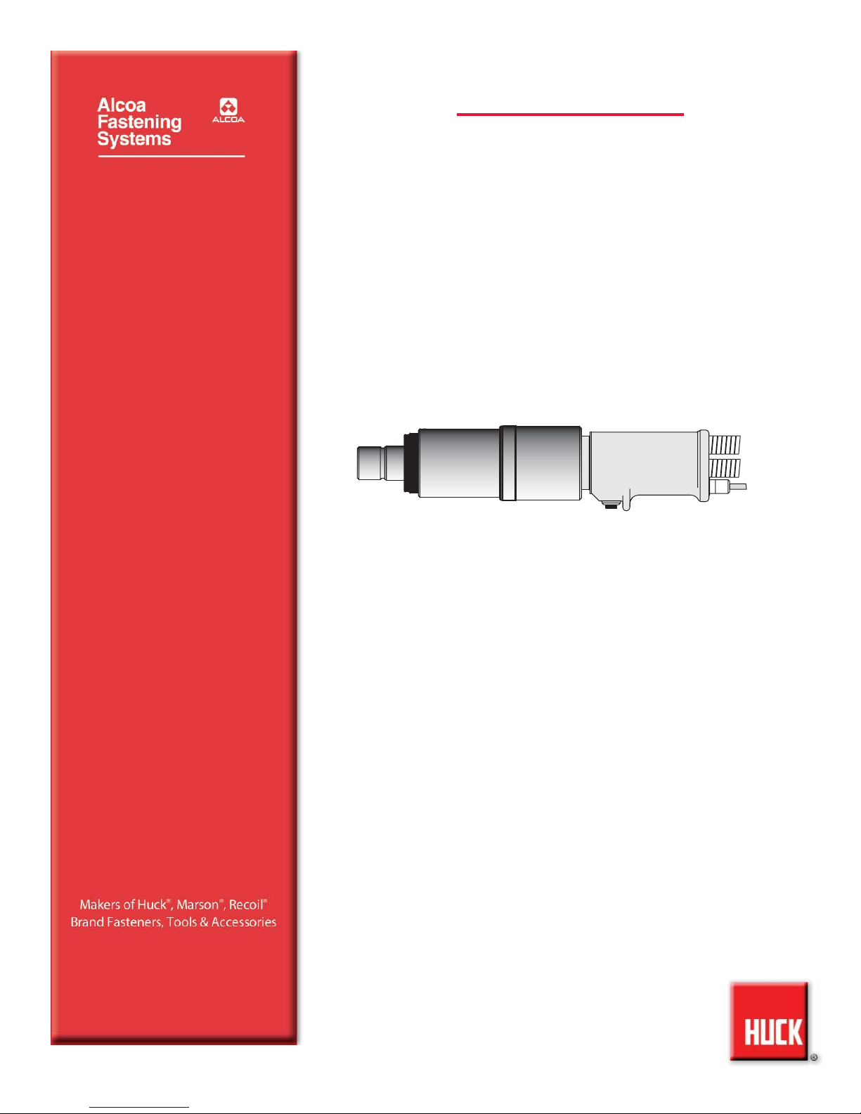
BOBTAIL INSTALLATION SYSTEM
BTT35LS
BTT35LS
Page 2

2
BTT35LS BOBTAIL Installation Tool Alcoa Fastening Systems
Page 3

3
BTT35LS BOBTAIL Installation Tool Alcoa Fastening Systems
SAFETY
. . . . . . . . . . . . . . . . . . . . . . . . . . . . . . . . . . . . . . . . . . . . . . . . . . .4
DESCRIPTION AND PRINCIPLE OF OPERATION
. . . . . . . . . . . . . . . . . . . . .5
TOOL SPECIFICATIONS
. . . . . . . . . . . . . . . . . . . . . . . . . . . . . . . . . . . . . . .6
PREPARATION FOR USE
. . . . . . . . . . . . . . . . . . . . . . . . . . . . . . . . . . . . . .7
OPERATING INSTRUCTIONS
. . . . . . . . . . . . . . . . . . . . . . . . . . . . . . . . . . . .8
WRENCHING-UP OF PIPE THREADS
. . . . . . . . . . . . . . . . . . . . . . . . . . . . .8
MAINTENANCE
. . . . . . . . . . . . . . . . . . . . . . . . . . . . . . . . . . . . . . . . . . . . . .9
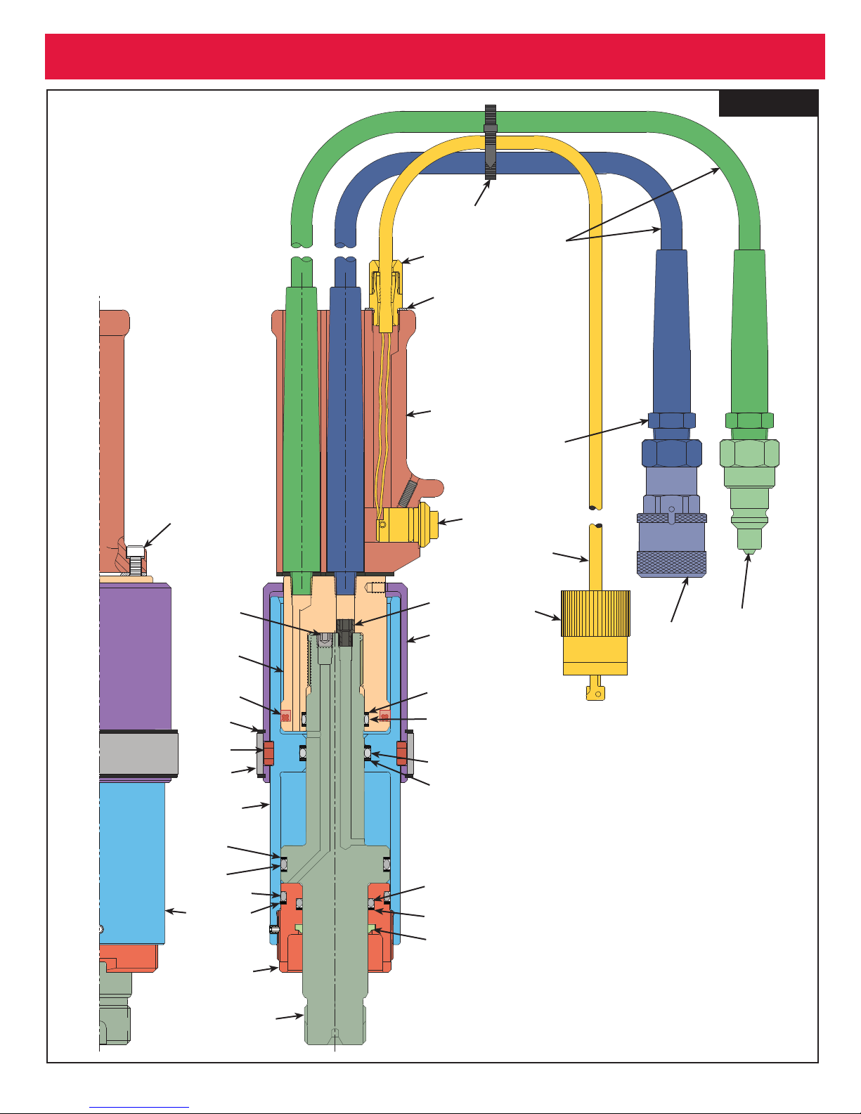
TOOL ASSEMBLY PARTS LIST
. . . . . . . . . . . . . . . . . . . . . . . . . . . . . . . .10
TOOL ASSEMBLY DRAWING
. . . . . . . . . . . . . . . . . . . . . . . . . . . . . . . . . .11
TROUBLESHOOTING
. . . . . . . . . . . . . . . . . . . . . . . . . . . . . . . . . . . . . . . . .12
OPTIONAL EQUIPMENT
. . . . . . . . . . . . . . . . . . . . . . . . . . . . . . . . . . . . . .12
C
C
ONTENTS
ONTENTS
Page 4
4
BTT35LS BOBTAIL Installation Tool Alcoa Fastening Systems
S
S
AFETY
AFETY
This instruction manual must be read,
with particular attention to the following
safety guidelines, by any person servicing or operating this tool.
1. Glossary
Notes - are reminders of required procedures.
Bold, Italic type and underlining
- empha-
sizes a specific instruction.
2. A half hour long hands-on training session with
qualified personnel is recommended before using
Huck equipment.
3. Huck equipment must be maintained in a safe
working condition at all times. Tools and hoses
should be inspected at the beginning of each
shift/day for damage or wear. Any repair should be
done by a qualified repairman trained on Huck procedures.
4. Repairman and Operator must read manual prior to
using equipment. Warning and Caution stickers/labels supplied with equipment must be understood before connecting equipment to any primary
power supply. As applicable, each of the sections
in this manual have specific safety and other information.
5. Read MSDS Specifications before servicing the
tool. MSDS Specifications are available from the
product manufacturer or your Huck representative.
6. When repairing or operating Huck installation
equipment, always wear approved eye protection.
Where applicable, refer to ANSI Z87.1 - 2003
7. Disconnect primary power source before perform-
ing maintenance on Huck equipment or changing
Nose Assembly.
8. Tools and hoses should be inspected for leaks at
the beginning of each shift/day. If any equipment
shows signs of damage, wear, or leakage, do not
connect it to the primary power supply.
9. Mounting hardware should be checked at the
beginning of each shift/day.
10. Make sure proper power source is used at all
times.
11. Release tool trigger if power supply is interrupted.
12. Tools are not to be used in an explosive environ-
ment unless specifically designed to do so.
13. Never remove any safety guards or pintail deflec-
tors.
14. Ensure deflector or pintail collector is installed and
operating prior to use.
15. Never install a fastener in free air. Personal injury
from fastener ejecting may occur.
16. Always clear spent pintail out of nose assembly
before installing the next fastener.
17. There is possibility of forcible ejection of pintails or
spent mandrels from front of tool.
18. If there is a pinch point between trigger and work
piece, use remote trigger. (Remote triggers are
available for all tooling).
19. Unsuitable postures may not allow counteracting of
normal expected movement of tool.
20. Do not abuse tool by dropping or using it as a ham-
mer. Never use hydraulic or air lines as a handle
or to bend or pry the tool. Reasonable care of
installation tools by operators is an important factor
in maintaining tool efficiency, eliminating downtime,
and in preventing an accident which may cause
severe personal injury.
21. Never place hands between nose assembly and
work piece. Keep hands clear from front of tool.
22. There is a risk of crushing if tool is cycled without
Nose Assembly installed.
23. Tools with ejector rods should never be cycled with
out nose assembly installed.
24. When two piece lock bolts are being used always
make sure the collar orientation is correct. See fastener data sheet of correct positioning.
25. Tool is only to be used as stated in this manual.
Any other use is prohibited.
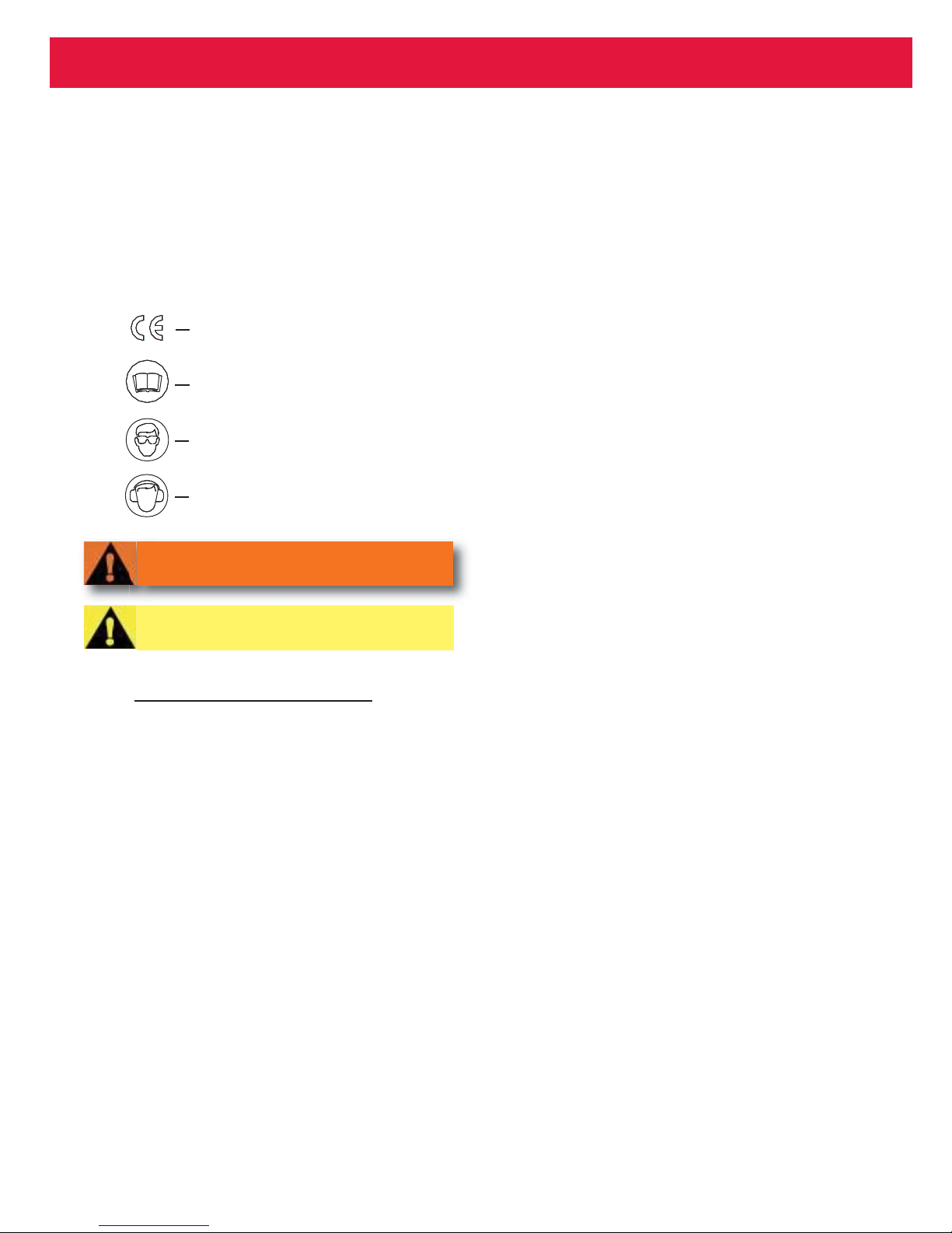
Product complies with requirements
set forth by the relevant European
directives.
Read manual prior to using
equipment.
Eye protection required while
using this equipment.
Hearing protection required while
using this equipment.
WARNINGS - Must be understood to
avoid severe personal injury.
CAUTIONS - show conditions that will
damage equipment and or structure.
Page 5
5
BTT35LS BOBTAIL Installation Tool Alcoa Fastening Systems
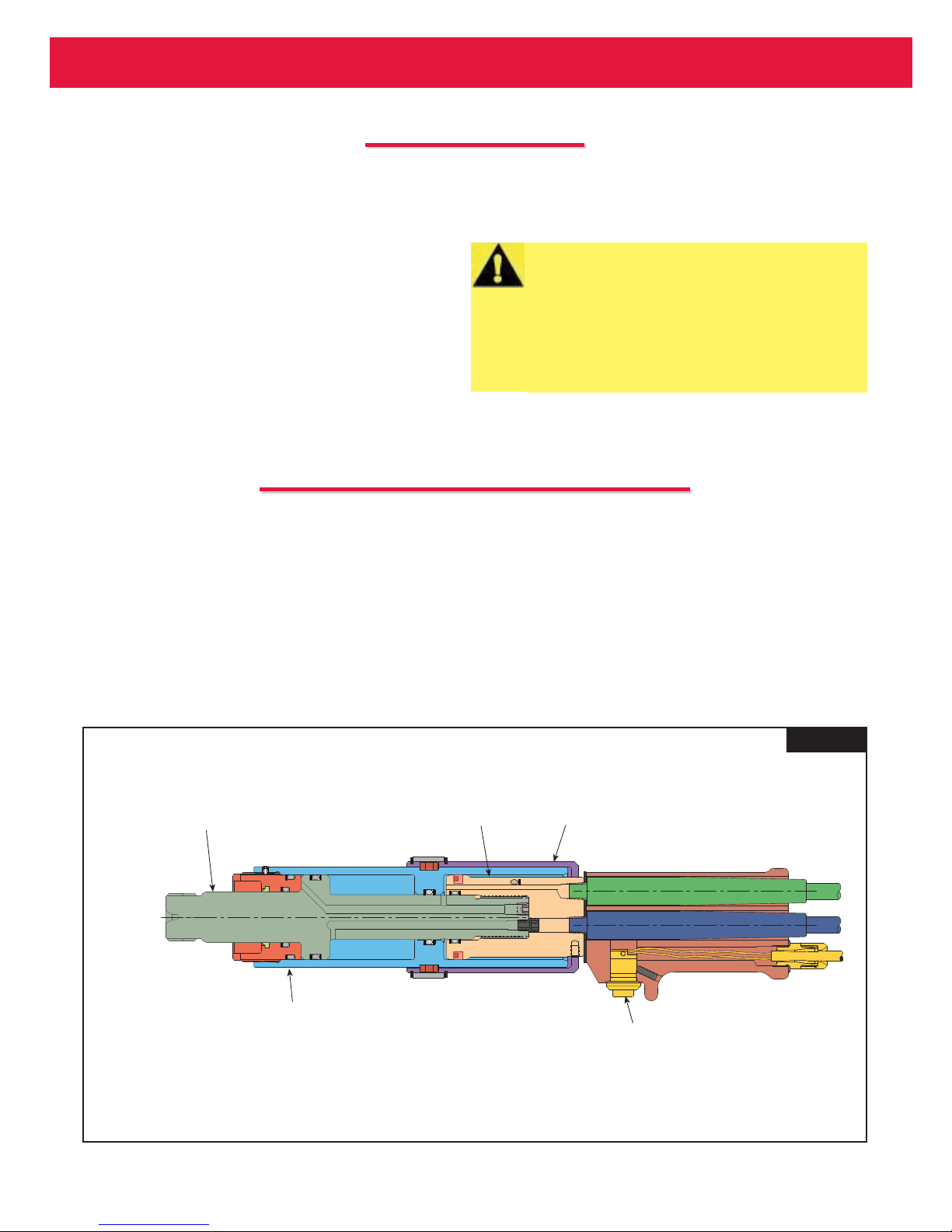
An electric trigger switch controls the PULL and
RETURN strokes of the tool. As the trigger is pressed,
hydraulic PULL pressure is directed to front sides of
both pistons, moving them rearward. Fastener
Installation begins.
When the fastener installation is complete, the trigger
is released, causing the hydraulic units combination
valve to redirect the hydraulic RETURN pressure to the
rear side of the front piston moving it forward. The nose
assembly, with the tool, is pushed off the installed fastener.
As the pistons reach the end of the RETURN stroke,
hydraulic pressure increases causing the hydraulic unit
idler valve to move to idle position (in Model 918) or
automatically shut off (in Model 940). The tool is now
ready to install another fastener.
P
P
RINCIPLE
RINCIPLE
OF
OF
O
O
PERATION
PERATION
HUCK Model BTT35LS is a Hydraulic Installation Tool
that installs and removes BOBTAIL fasteners in limited clearance applications.
This tool design consists of a cylinder housing with
two chambers to accommodate two tandem pull pistons. This feature increases pull capacity while maintaining optimum centerline-to-edge clearance and
lightweight.
The tool is intended for use with Huck standard industrial POWERIG® Hydraulic Units (models 913H, 918,
d 940, and 968) or equivalent - sold separately.
Except for nose assembly, tool is complete with
hydraulic hoses, couplings and electric control cord
ready to be attached to POWERIG® Hydraulic Units
hoses and control cord.
D
D
ESCRIPTION
ESCRIPTION
CAUTION: Huck recommends that only Huck
POWERIG® Hydraulic Unit be used as the
power source for Huck installation equipment. Hydraulic power units that deliver
high pressure for both PULL and RETURN,
and are not equipped with relief valves are
specifically not recommended, and may be
dangerous.
Figure 1
Front Piston
Front of Tool
Main Housing
Rear Piston
Rear Piston Shield
Trigger
Page 6
6
BTT35LS BOBTAIL Installation Tool Alcoa Fastening Systems
S
S
PECIFICATIONS
PECIFICATIONS
Power Source: Huck POWERIG Hydraulic Unit
Hose Kits: Use only genuine HUCK Hose Kits rated
@ 10,000 psi working pressure.
Hydraulic Fluid: ATF meeting DEXRON III, DEXRON
IV, MERCON, Allison C-4 or equivalent specifications.
Fire resistant hydraulic fluid may also be used, and is
required to comply with OSHA regulation 1926.302
paragraph (d): "the fluid used in hydraulic power tools
shall be fire resistant fluid approved under schedule 30
of the US Bureau of Mines, Department of Interior, and
shall retain its operating characteristics at the most
extreme temperatures to which it will be exposed."
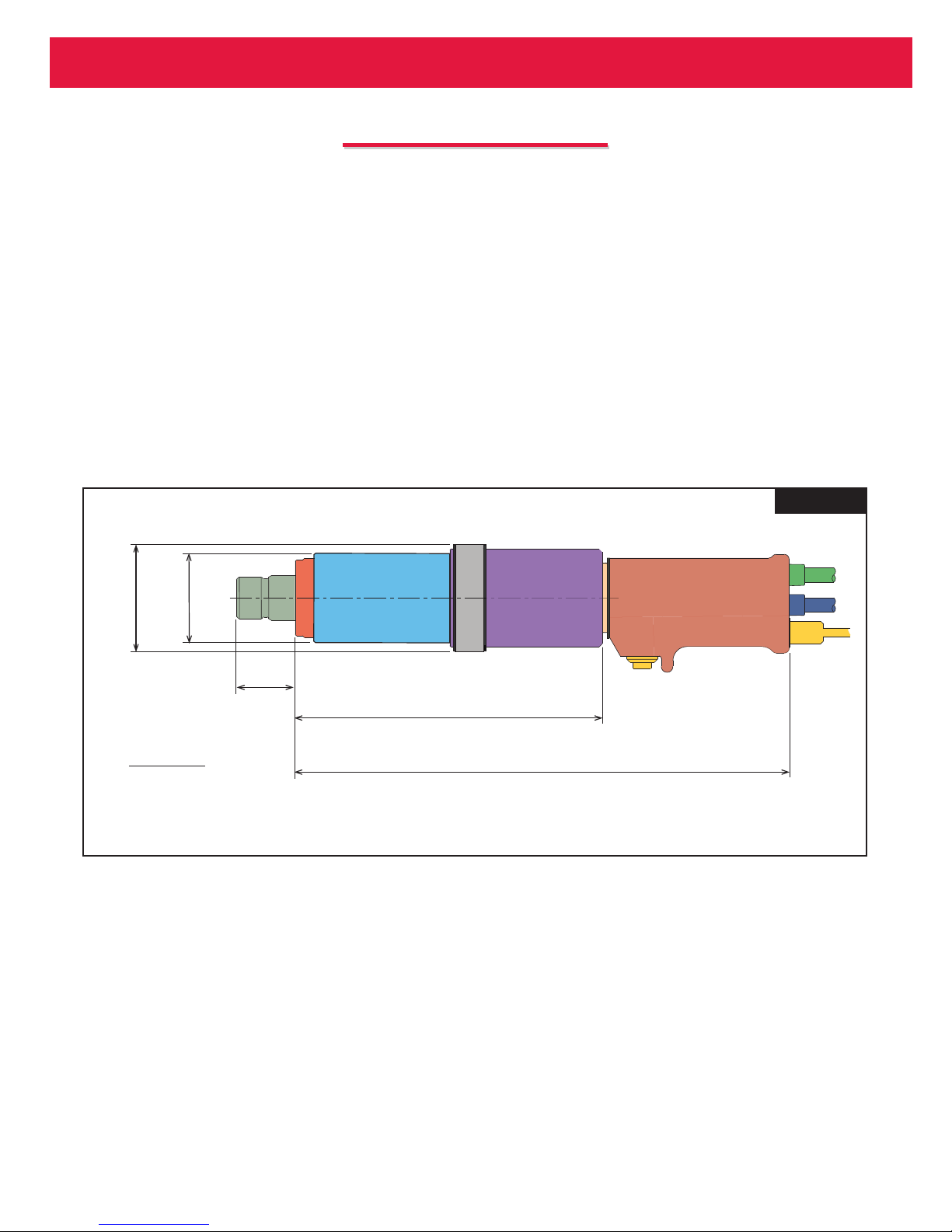
Tool PULL Capacity: 35,000 lbs
PULL Pressure: 8000 psi MAX
RETURN Pressure: 6500 psi MAX
Stroke: 2.50 inches
Figure 2
2.87
2.38
(72.8)
(60.4)
INCHES
(mm)
2.83
(71.8)
9.06
(230)
15.32
(389.1)
Page 7
7
BTT35LS BOBTAIL Installation Tool Alcoa Fastening Systems
POWER SOURCE CONNECTIONS
Coat hose fitting threads with a non-hardening
Teflon
TM
thread compound such as Slic-tite.
TM
(Slic-tite is available from Huck as P/N 503237.)
2. Use only a HUCK Powerig that is recommended
or equivalent that has been prepared for operation per applicable instruction manual. Check
both PULL and RETURN pressures and adjust as
necessary to match installation tool. Gage part
number T-124833(new), for checking POWERIG
pressures is available from Huck.
3. Turn POWERIG to “OFF” and couple tool hoses
to POWERIG hoses.
4. Turn POWERIG to “ON” and depress and release
trigger a few times to circulate hydraulic fluid.
Observe action of tool. Check for fluid leaks.
5. Attach the proper Nose Assembly to the tool.
P
P
REPARATION
REPARATION
FOR
FOR
U
U
SE
SE
CAUTION: Do not let disconnected hoses
and couplers contact a dirty floor. Keep
harmful material out of hydraulic fluid. Dirt
in hydraulic fluid causes valve failure In Tool
and In POWERIG Hydraulic Unit.
WARNINGS:
Read full manual before using tool.
A half-hour training session with qualified
personnel is recommended before using
Huck equipment.
When operating Huck installation equipment, always wear approved eye protection.
Be sure there is adequate clearance for the
operator’s hands before proceeding.
CAUTION: Do not use TEFLON®* tape on pipe
threads. Pipe threads may cause tape to shred
resulting in tool malfunction. (Slic-Tite is available in stick form as Huck P/N 503237.)
WARNING: Correct PULL and RETURN pressures are required for operator’s safety and
for Installation TooI’s function. Gauge Set-Up,
T-124833 and T-124833CE, Is available for
checking pressures. See Tool S
PECIFICATIONS
and Gauge Instruction Manual. Failure to verify pressures may result in severe personal
injury.
WARNING: Be sure to connect Tool’s
hydraulic hoses to POWERIG Hydraulic Unit
before connecting Tool’s switch control cord
to unit. If not connected in this order, severe
personal Injury may occur.
CAUTION: Hose couplers must be completely
screwed together to insure that ball checks
in both nipple and body are completely open.
Improperly assembled couplers will cause
overheating and malfunctions in both tool
and Powerig. Hand tighten couplers. Do NOT
use a pipe wrench.
Page 8

8
BTT35LS BOBTAIL Installation Tool Alcoa Fastening Systems
O
O
PERATING
PERATING
I
I
NSTRUCTIONS
NSTRUCTIONS
:
:
1. Push the tool’s nose over the end of the fastener until it
bottoms out.
2. Press the trigger and hold until the collar is swaged and
the tool’s Anvil is ejected off the collar and the tool is
released from the fastener.
WARNING: To avoid pinch
point, never place hand
between nose assembly
and work piece.
WARNING: Only use compatible equipment with
this tool.
W
W
RENCHING
RENCHING
-
-
UP
UP
OF
OF
P
P
IPE
IPE
T
T
HREADS
HREADS
The following table pertains to 1/8, 1/4, and 3/8 NPTF joints in this product. All turn counts listed are beyond
hand-tight. Teflon stick or equivalent (NOT tape) must be used without exception.
Pipe Thread Size Number of Turns
1/8 NPTF 2 - 2
1
⁄4
1/4 NPTF 1
1
⁄2
- 1
3
⁄4
3/8 NPTF 1
1
⁄2
- 1
3
⁄4
Table 2 - Wrenching-up of Pipe Threads
Page 9
9
BTT35LS BOBTAIL Installation Tool Alcoa Fastening Systems
M
M
AINTENANCE
AINTENANCE
• The efficiency and life of your tool depends on proper
maintenance. Please read this section completely
before proceeding with maintenance and repair. Use
proper hand tools in a clean and well-lighted area.
Only standard hand tools are required in most cases.
Where a special tool is required, the description and
part number are given.
• While clamping tool or parts in a vise, and when
parts require force, use suitable soft materials to
cushion impact. For example, using a half-inch brass
drift, wood block and vise with soft jaws greatly
reduces possibility of damaging tool. Remove components in a straight line without bending, cocking or
undue force. Reassemble tool with the same care
.
Sealants, Lubricants, Service Kits
• See SS
PECIFICATIONS
PECIFICATIONS
for fluid type. Dispose of fluid
in accordance with local environmental regulations.
Recycle steel, aluminum, and plastic parts in accordance with local lawful and safe practices.
• Rub Slic-Tite®* with PTFE thread compound, or
equivalent, on pipe plug threads and quick connect
fitting.
• Smear LUBRIPLATE®13OAA*, or equivalent lubri-
cant, on O-Rings and mating surfaces to aid assembly and to prevent damage to O-Rings.
(LUBRIPLATE 13O-AA is available in a tube as
Huck P/N 502723.)
• Each Service Kit contains perishable parts for your
specific tool. As foreseeable use may indicate, keep
extra kits (O-rings, Back-up Rings, other standard
items) and tool parts in stock. When stock is depleted, you can get kit items from any regular retailer of
these items. See kit parts list for: O-ring size
(AS568- number); material; durometer.
PREVENTIVE MAINTENANCE
System Inspection
Operating efficiency of the tool is directly related to the
performance of the complete system, including the tool
with nose assembly, hydraulic hoses, trigger and control cord, and POWERIG. Therefore, an effective preventive maintenance program includes scheduled
inspections of the system to detect and correct minor
troubles. At the beginning of each shift/day:
• Inspect tool and nose assembly for external damage.
• Verify that hydraulic hose fittings, couplings, and
electrical connections are secure.
• Inspect hydraulic hoses for damage and deterioration. Do not use hoses to carry tool. Replace hoses
if damaged.
• Observe tool, hoses, and hydraulic unit during operation to detect abnormal heating, leaks, or vibration.
• Max hydraulic fluid contamination level: NAS 1638
class 9, or ISO CODE 18/15, or SAE level 6.
POWERIG Maintenance
Maintenance instructions and repair procedures are
in the appropriate POWERIG Instruction Manual.
Tool Maintenance
Whenever disassembled and also at regular intervals
(depending on severity and length of use), replace all
seals, wipers, and back-up rings in tool. Service Kits,
hoses, and extra parts should be kept in stock.
Inspect cylinder bore, pistons, and piston rods for
scored surfaces and excessive wear or damage.
Replace as necessary.
Nose Assembly Maintenance
Clean nose assembly often. Dip in mineral spirits or
similar solvent to clean puller and wash away metal
chips and debris. At regular intervals, as experience
shows, disassemble nose and use a sharp "pick" to
remove imbedded particles from grooves of puller.
* DEXRON is a registered trademark of General Motors Corp.
Quintolubric is a registered trademark of Quaker Chemical Corp.
Slic-Tite is a registered trademark of LA-CO Industries, Inc.
TEFLON is a registered trademark of DuPont Corp.
LUBRIPLATE is a registered trademark of Fiske Brothers
Refining Co.
WARNING: Inspect tool for damage or
wear before each use. Do not operate if
damaged or worn, as severe personal
injury may occur.
CAUTIONS:
- Consult MSDS before servicing tool.
- Keep dirt and other material out of
hydraulic system.
- Separated parts most be kept away from
dirty work surfaces.
- Dirt/debris in hydraulic fluid causes failure
in POWERIG® Hydraulic Unit’s valves.
CAUTION: Do not use TEFLON®* tape on pipe
threads. Pipe threads may cause tape to shred
resulting in tool malfunction. (Slic-Tite®* is
available in stick form as Huck P/N 503237.)
CAUTION: Always replace seals, wipers,
and back-up rings when tool is disassembled for any reason.
Page 10

10
BTT35LS BOBTAIL Installation Tool Alcoa Fastening Systems
ITEM DESCRIPTION BTT35LS QTY.
1* Piston Assembly 128955 1
1a Piston Rod n/a 1
1b Pipe Plug 503703 1
1c O-Ring 506089 1
1d Back-up Ring 501151 2
2* Forward Gland Assembly 121890 1
2a Forward Gland n/a 1
2b Wiper 506065 1
2c O-Ring 506089 1
2d Back-up Ring 501151 1
2e O-Ring 506079 1
2f Back-up Ring 501144 1
3* Main Housing Assembly 128953 1
3a Main Housing n/a 1
3b Lockscrew 121343-35 2
3c O-Ring 506078 1
3d Back-up Ring 501142 2
4* RearPiston Assembly 128957 1
4a Rear Piston n/a 1
4b Polyseal 505918 1
4c O-Ring 500818 1
4d Back-up Ring 501112 2
5 Sleeve 125904 1
6 Retaining Ring 507474 2
7 Locator Button 125902 2
8 Shield 128959 1
9 Locking Screw 119016 1
10 Screw 501269 4
11 Handle Assembly 122628 1
11a Handle 122278 1
11b* Trigger Cord Assembly 119812-2 1
11b1 Trigger Switch Assembly 120361 1
11b2 Strain Relief 505344 1
11b3 Washer 506185 1
11b4 Male Connector 110686 1
11b5 Cord n/a 1
12 High Pressure Hose 118944-2 2
13 Reducer 503431 2
14 Coupler Body 110439 1
15 Coupler Nipple 110438 1
16 Cable Tie 505839 1
17 CAUTION Sticker 590259 1
T
T
OOL
OOL
A
A
SSEMBLY
SSEMBLY
P
P
ARTS
ARTS
L
L
IST
IST
(Figures 5 and 6)
These parts are also
included in the tool Service
Kit HPT35KIT.
* When replacing these
parts, the assembly must
be ordered. One or more
individual sub-components
are not sold separately.
Page 11
11
BTT35LS BOBTAIL Installation Tool Alcoa Fastening Systems
Figure 5
16
10
1b
11b2
11b3
11a
9
8
11b1
11b5
11b4
12
13(2)
15
14
4b 4a
6(2)57(2)
3a
1c 1d(2)
2c
17
2d
2a
1a
4d(2)
4c
3c
3d(2)
2e
2f
2b
Page 12

12
BTT35LS BOBTAIL Installation Tool Alcoa Fastening Systems
T
T
ROUBLESHOOTING
ROUBLESHOOTING
Always check the simplest possible cause of a malfunction first. For example, a loose or disconnected
trigger line. Then proceed logically and eliminate each
possible cause until the defect is found. Where possible, substitute known good parts for suspected defective parts. Use chart as an aid in troubleshooting.
1. Tool fails to operate when trigger is pressed.
a. Inoperative POWERIG® Hydraulic Unit. See
applicable instruction manual.
b. Loose electrical connections.
c. Damaged trigger assembly.
d. Loose or faulty hose coupling.
2. Tool operates in reverse.
a. Reversed hose connections between hydraulic
unit and tool.
3. Tool leaks hydraulic fluid.
a. Defective tool o-rings or loose connections at
tool.
4. Hydraulic couplers leak fluid.
a. Damaged or worn O-rings in coupler body cou-
pler P/N 110440.
5. Hydraulic fluid overheats.
a. Unit not operating properly. See units manual.
b. Unit running in reverse (918; 918-5 only). See
unit’s manual.
6. Tool operates erratically and fails to install fastener
properly.
a. Low or erratic hydraulic pressure: Air in system.
b. Damaged or worn piston o-ring in tool.
c. Excessive wear on sliding surfaces of tool parts.
7. Pull grooves on fastener pintail stripped during
PULL stroke.
a. Operator not sliding anvil completely onto fas-
tener pintail.
b. Incorrect fastener grip.
c. Worn or damaged jaw segments.
d. Metal particles in jaw grooves.
e. Excessive sheet gap.
8. Collar of fastener not completely swaged.
a. Improper tool operation. See No. 6.
b. Scored anvil.
9. Tool "hangs up" on swaged collar of fastener.
a. Improper tool operation. See No. 6.
b. RETURN pressure too low.
c. Not enough collar lubricant.
d. Nose assembly not installed correctly.
10. Pintail of fastener fails to break.
a. Improper tool operation. See No. 6.
b. Pull grooves on fastener stripped. See No. 7.
c. PULL pressure too low.
11. Nose will not release broken pintail.
a. Nose assembly not installed correctly.
O
O
PTIONAL
PTIONAL
E
E
QUIPMENT
QUIPMENT
Service Kit - HPT35KIT (contains O-Rings, back-up Rings, Wiper, POLYSEAL, and various size HEX keys for tool service)
Teflon Stick - 503237
Loctite* 242 - 505016
*Loctite is a trademark of Henkel Corporation, U.S.A.
Anti-seize Lubricant - 508183
High Pressure Right Angle Connector Kit - 122002
Control Cord Kit (Joy Connectors) - 121248
Page 13

13
Alcoa Fastening Systems
L
L
IMITED
IMITED
W
W
ARRANTIES
ARRANTIES
TOOLING WARRANTY:
Huck warrants that tooling and other items (excluding
fasteners, and hereinafter referred as "other items")
manufactured by Huck shall be free from defects in
workmanship and materials for a period of ninety (90)
days from the date of original purchase.
WARRANTY ON "NON STANDARD OR CUSTOM
MANUFACTURED PRODUCTS":
With regard to non-standard products or custom manufactured products to customer's specifications, Huck
warrants for a period of ninety (90) days from the date
of purchase that such products shall meet Buyer's
specifications, be free of defects in workmanship and
materials. Such warranty shall not be effective with
respect to non-standard or custom products manufactured using buyer-supplied molds, material, tooling
and fixtures that are not in good condition or repair
and suitable for their intended purpose.
THERE ARE NO WARRANTIES WHICH EXTEND
BEYOND THE DESCRIPTION ON THE FACE
HEREOF. HUCK MAKES NO OTHER WARRANTIES AND EXPRESSLY DISCLAIMS ANY
OTHER WARRANTIES, INCLUDING IMPLIED
WARRANTIES AS TO MERCHANTABILITY OR AS
TO THE FITNESS OF THE TOOLING, OTHER
ITEMS, NONSTANDARD OR CUSTOM MANUFACTURED PRODUCTS FOR ANY PARTICULAR PURPOSE AND HUCK SHALL NOT BE LIABLE FOR
ANY LOSS OR DAMAGE, DIRECTLY OR INDIRECTLY, ARISING FROM THE USE OF SUCH
TOOLING, OTHER ITEMS, NONSTANDARD OR
CUSTOM MANUFACTURED PRODUCTS OR
BREACH OF WARRANTY OR FOR ANY CLAIM
FOR INCIDENTAL OR CONSEQUENTIAL DAMAGES.
Huck's sole liability and Buyer's exclusive remedy for
any breach of warranty shall be limited, at Huck's
option, to replacement or repair, at FOB Huck's plant,
of Huck manufactured tooling, other items, nonstandard or custom products found to be defective in
specifications, workmanship and materials not otherwise the direct or indirect cause of Buyer supplied
molds, material, tooling or fixtures. Buyer shall give
Huck written notice of claims for defects within the
ninety (90) day warranty period for tooling, other
items, nonstandard or custom products described
above and Huck shall inspect products for which such
claim is made.
TOOLING, PART(S) AND OTHER ITEMS NOT MANU-
FACTURED BY HUCK:
HUCK MAKES NO WARRANTY WITH RESPECT
TO THE TOOLING, PART(S) OR OTHER ITEMS
MANUFACTURED BY THIRD PARTIES. HUCK
EXPRESSLY DISCLAIMS ANY WARRANTY
EXPRESSED OR IMPLIED, AS TO THE CONDITION, DESIGN, OPERATION, MERCHANTABILITY
OR FITNESS FOR USE OF ANY TOOL, PART(S),
OR OTHER ITEMS THEREOF NOT MANUFACTURED BY HUCK. HUCK SHALL NOT BE LIABLE
FOR ANY LOSS OR DAMAGE, DIRECTLY OR INDIRECTLY, ARISING FROM THE USE OF SUCH
TOOLING, PART(S) OR OTHER ITEMS OR
BREACH OF WARRANTY OR FOR ANY CLAIM
FOR INCIDENTAL OR CONSEQUENTIAL DAMAGES.
The only warranties made with respect to such tool,
part(s) or other items thereof are those made by the
manufacturer thereof and Huck agrees to cooperate
with Buyer in enforcing such warranties when such
action is necessary.
Huck shall not be liable for any loss or damage resulting from delays or nonfulfillment of orders owing to
strikes, fires, accidents, transportation companies or
for any reason or reasons beyond the control of the
Huck or its suppliers.
HUCK INSTALLATION EQUIPMENT:
Huck International, Inc. reserves the right to make
changes in specifications and design and to discontinue models without notice.
Huck Installation Equipment should be serviced by
trained service technicians only.
Always give the Serial Number of the equipment
when corresponding or ordering service parts.
Complete repair facilities are maintained by Huck
International, Inc. Please contact one of the offices
listed below.
Eastern
One Corporate Drive Kingston, New York 12401-0250
Telephone (845) 331-7300 FAX (845) 334-7333
Outside USA and Canada
Contact your nearest Huck International Office, see
back cover.
In addition to the above repair facilities, there are
Authorized Tool Service Centers (ATSC's) located
throughout the United States. These service centers
offer repair services, spare parts, Service Parts Kits,
Service Tools Kits and Nose Assemblies. Please contact your Huck Representative or the nearest Huck
office listed on the back cover for the ATSC in your
area.
Page 14
Americas
Alcoa Fastening Systems
Aerospace Products
Tucson Operations
3724 East Columbia
Tucson, AZ 85714
800-234-4825
520-747-9898
FAX: 520-748-2142
Alcoa Fastening Systems
Aerospace Products
Carson Operations
PO Box 5268
900 Watson Center Rd.
Carson, CA 90749
800-421-1459
310-830-8200
FAX: 310-830-1436
Alcoa Fastening Systems
Industrial Products
Waco Operations
PO Box 8117
8001 Imperial Drive
Waco, TX 76714-8117
800-388-4825
254-776-2000
FAX: 254-751-5259
Alcoa Fastening Systems
Industrial Products
Kingston Operations
1 Corporate Drive
Kingston, NY 12401
800-278-4825
845-331-7300
FAX: 845-334-7333
Alcoa Fastening Systems
Industrial Products
Latin America Operations
Avenida Parque Lira. 79-402
Tacubaya Mexico, D.F.
C.P. 11850
FAX: 525-515-1776
TELEX: 1173530 LUKSME
Far East
Alcoa Fastening Systems
Industrial Products
Australia Operations
14 Viewtech Place
Rowville, Victoria
Australia 3178
03-764-5500
Toll Free: 008-335-030
FAX: 03-764-5510
Europe
Alcoa Fastening Systems
Industrial Products
United Kingdom Operations
Unit C, Stafford Park 7
Telford, Shropshire
England TF3 3BQ
01952-290011
FAX: 0952-290459
Alcoa Fastening Systems
Aerospace Products
France Operations
Clos D’Asseville
BP4
95450 Us Par Vigny
France
33-1-30-27-9500
FAX: 33-1-34-66-0600
A Global Organization
Alcoa Fastening Systems (AFS) maintains
company offices throughout the United States
and Canada, with subsidiary offices in many
other countries. Authorized AFS distributors
are also located in many of the world’s
Industrial and Aerospace centers, where they
provide a ready source of AFS fasteners,
installation tools, tool parts, and application
assistance.
For The Long Haul, The Future of Fastening
Technology, The Future of Assembly Technology,
The Future of Tooling Technology, and Tools of
Productivity are service marks of Huck
International. Huck provides technical assistance
regarding the use and application of Huck fasteners and tooling.
NOTICE: The information contained in this publication is only for general guidance with regard to
properties of the products shown and/or the
means for selecting such products, and is not
intended to create any warranty, express,
implied, or statutory; all warranties are contained
only in Huck’s written quotations, acknowledgements, and/or purchase orders. It is recommended that the user secure specific, up-to-date data
and information regarding each application
and/or use of such products.
HWB898 1003-5M
© 2003 Alcoa Fastening Systems
1 Corporate Drive, Kingston, NY 12401 • Tel: 800-431-3091 • Fax: 845-334-7333 • www.alcoafasteningsystems.com
Certified to
ISO 14001:2004
Industrial
Products
Certified to
ISO 9001:2008
Industrial
Products
One Great Connection
SM
Alcoa Fastening Systems world-wide locations:
For the Long Haul
™
 Loading...