

Page 1
02-27-2012
HK1012
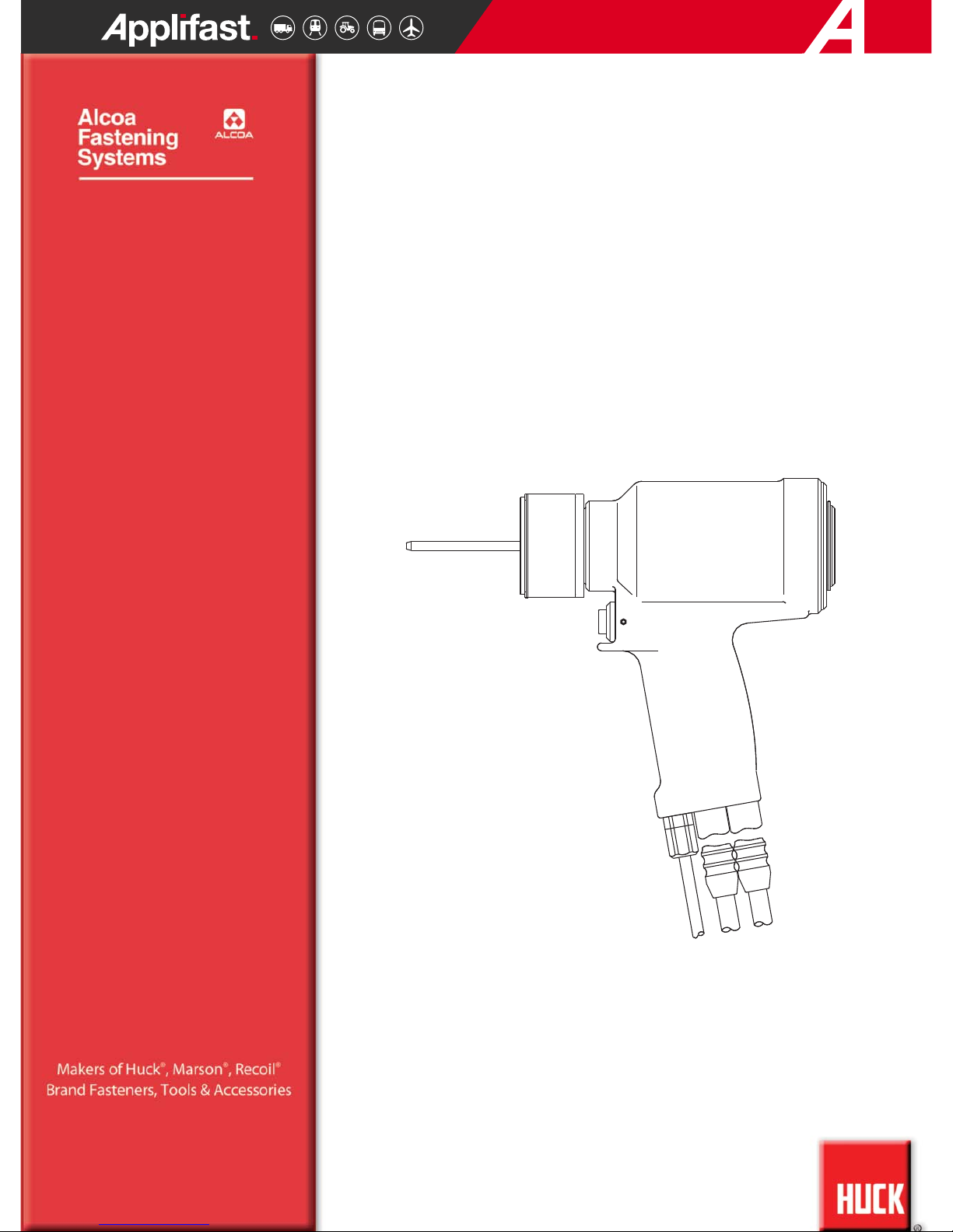
INSTRUCTION MANUAL
2620
2620
A2620
A2620
2620-PT
2620-PT
A2620-PT
A2620-PT
HYDRAULIC INSTALLATION TOOLS
Toll Free 1 800 563 1293
Distributed by
Page 2
Page 3

2620 series Tooling (HK1012) Alcoa Fastening Systems
3
EU DECLARATION OF CONFORMITY
. . . . . . . . . . . . . . . . . . . . . . . . . . . . .2
CONTENTS
. . . . . . . . . . . . . . . . . . . . . . . . . . . . . . . . . . . . . . . . . . . . . . . . .3
SAFETY
. . . . . . . . . . . . . . . . . . . . . . . . . . . . . . . . . . . . . . . . . . . . . . . . . . .4
PRINCIPLE OF OPERATION
. . . . . . . . . . . . . . . . . . . . . . . . . . . . . . . . . . . .5
SPECIFICATIONS
. . . . . . . . . . . . . . . . . . . . . . . . . . . . . . . . . . . . . . . . . . .6-7
PREPARATION FOR USE
. . . . . . . . . . . . . . . . . . . . . . . . . . . . . . . . . . . . . .8
OPERATING INSTRUCTIONS
. . . . . . . . . . . . . . . . . . . . . . . . . . . . . . . . . . . .9
SERVICING THE TOOL
. . . . . . . . . . . . . . . . . . . . . . . . . . . . . . . . . . . . . . . .9
DISASSEMBLY
. . . . . . . . . . . . . . . . . . . . . . . . . . . . . . . . . . . . . . . . . . . . .10
ASSEMBLY
. . . . . . . . . . . . . . . . . . . . . . . . . . . . . . . . . . . . . . . . . . . . . . . .11
TOOL HEAD DRAWINGS
. . . . . . . . . . . . . . . . . . . . . . . . . . . . . . . . . . .12-14
PARTS LISTS
. . . . . . . . . . . . . . . . . . . . . . . . . . . . . . . . . . . . . . . . . . . . . .15
STICKER LOCATIONS
. . . . . . . . . . . . . . . . . . . . . . . . . . . . . . . . . . . . . . . .15
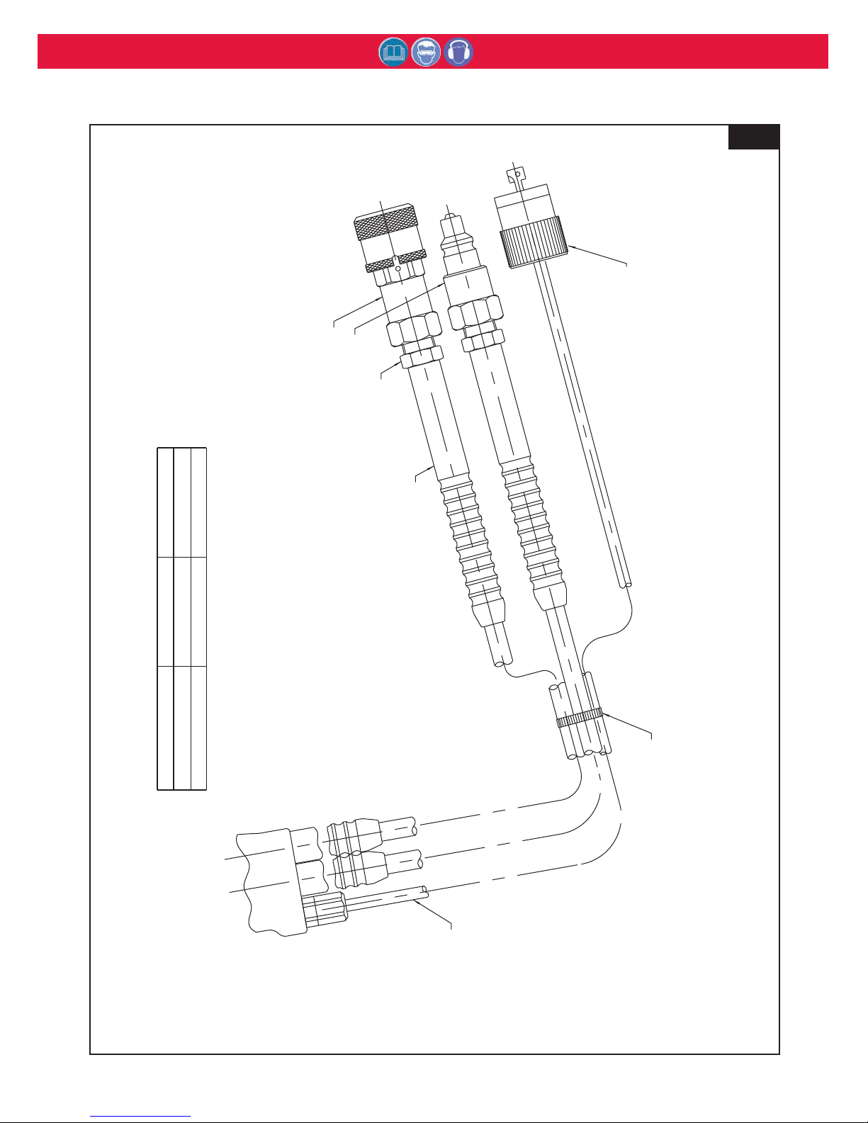
HOSE ASSEMBLY DRAWING - ELECTRIC TRIGGER MODELS
. . . . . . . .16
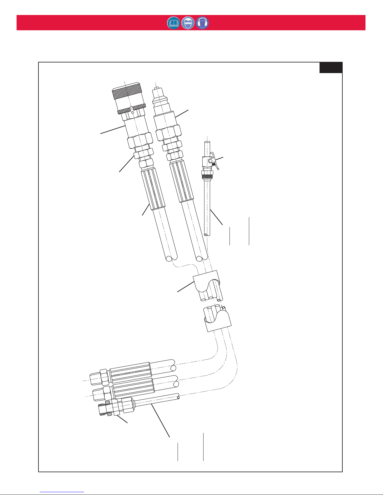
HOSE ASSEMBLY DRAWING - AIR TRIGGER MODELS
. . . . . . . . . . . . .17
TROUBLESHOOTING
. . . . . . . . . . . . . . . . . . . . . . . . . . . . . . . . . . . . . . . . .18
KITS & ACCESSORIES
. . . . . . . . . . . . . . . . . . . . . . . . . . . . . . . . . . . . . . .18
C
C
ONTENTS
ONTENTS
Page 4
2620 series Tooling (HK1012) Alcoa Fastening Systems
4
1. A half hour long hands-on training session with qualified
personnel is recommended before using Huck equipment.
2. Huck equipment must be maintained in a safe working
condition at all times. Tools and hoses should be inspected at
the beginning of each shift/day for damage or wear. Any repair
should be done by a qualified repairman trained on Huck
procedures.
3. Repairman and Operator must read manual prior to using
equipment. Warning and Caution stickers/labels supplied with
equipment must be understood before connecting equipment
to any primary power supply. As applicable, each of the
sections in this manual have specific safety and other
information.
4. Read MSDS Specifications before servicing the tool. MSDS
Specifications are available from the product manufacturer or
your Huck representative.
5. When repairing or operating Huck installation equipment,
always wear approved eye protection. Where applicable, refer
to ANSI Z87.1 - 2003
6. Only genuine Huck parts shall be used for replacements or
spares. Use of any other parts can result in tooling damage or
personal injury.
7. If a part affixed with warning labels is replaced, or labels are
missing or damaged, the end user is responsible for
replacement. Refer to assembly drawing and parts list for
replacement part number and proper placement.
8. Disconnect primary power source before performing
maintenance on Huck equipment or changing Nose Assembly.
9. Tools and hoses should be inspected for leaks at the
beginning of each shift/day. If any equipment shows signs of
damage, wear, or leakage, do not connect it to the primary
power supply.
10. Mounting hardware should be checked at the beginning of
each shift/day.
11. Make sure proper power source is used at all times.
12. Release tool trigger if power supply is interrupted.
13. Tools are not to be used in an explosive environment unless
specifically designed to do so.
14. Never remove any safety guards or pintail deflectors.
15. Where applicable, ensure deflector or pintail collector is
installed and operating prior to use.
16. Never install a fastener in free air. Personal injury from
fastener ejecting may occur.
17. Where applicable, always clear spent pintail out of nose
assembly before installing the next fastener.
18. There is possibility of forcible ejection of pintails or spent
mandrels from front of tool.
19. Check clearance between trigger and work piece to ensure
there is no pinch point when tool is activated. Remote triggers
are available for hydraulic tooling if pinch point is unavoidable.
20. Unsuitable postures may not allow counteracting of normal
expected movement of tool.
21. Do not abuse tool by dropping or using it as a hammer. Never
use hydraulic or air lines as a handle or to bend or pry the
tool. Reasonable care of installation tools by operators is an
important factor in maintaining tool efficiency, eliminating
downtime, and in preventing an accident which may cause
severe personal injury.
22. Never place hands between nose assembly and work piece.
Keep hands clear from front of tool.
23. There is a risk of crushing if tool is cycled without Nose
Assembly installed.
24. Tools with ejector rods should never be cycled with out nose
assembly installed.
25. When two piece lock bolts are being used always make sure
the collar orientation is correct. See fastener data sheet for
correct positioning.
26. Tool is only to be used as stated in this manual. Any other use
is prohibited.
27. There is a risk of whipping compressed air hose if tool is
pneudraulic or pneumatic.
28. Release the trigger in case of failure of air supply or hydraulic
supply.
29. Use only fluids or lubricants recommended.
30. Disposal instruction: Disassemble and recycle steel, aluminum
and plastic parts, and drain and dispose of hydraulic fluid in
accordance with local lawful and safe practices.
31. If tool is fixed to a suspension device, ensure that the device is
secure prior to operating the tool.
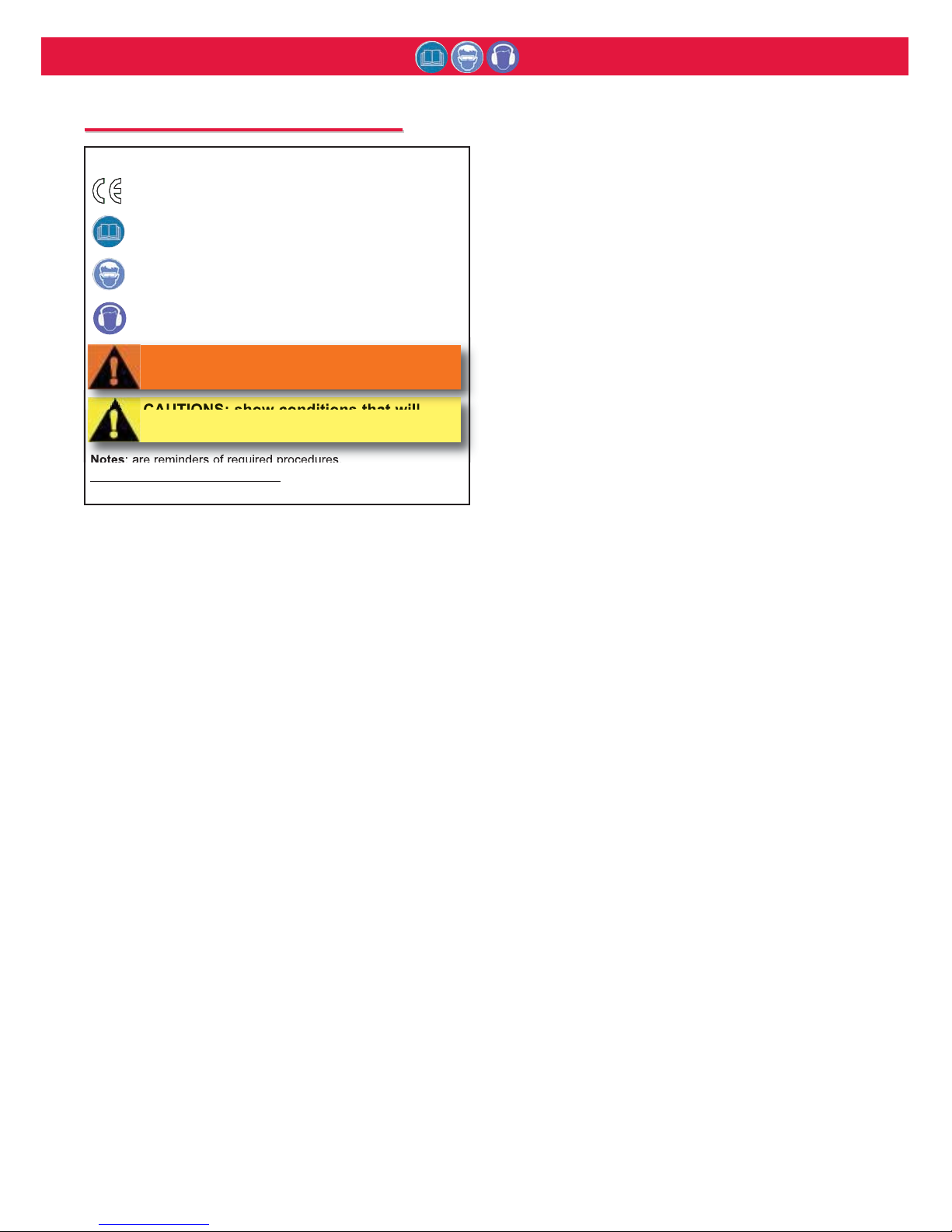
GLOSSARY OF TERMS AND SYMBOLS:
- Product complies with requirements set forth by the
relevant European directives.
- READ MANUAL prior to using this equipment.
- EYE PROTECTION IS REQUIRED while using this
equipment.
- HEARING PROTECTION IS REQUIRED while using
this equipment.
Notes: are reminders of required procedures.
Bold, Italic type and underlining
: emphasizes a specific
instruction.
S
S
AFETY
AFETY
I
I
NSTRUCTIONS
NSTRUCTIONS
CAUTIONS: show conditions that will
damage equipment and or structure.
WARNINGS: Must be understood to avoid
severe personal injury.
Page 5
2620 series Tooling (HK1012) Alcoa Fastening Systems
5
5
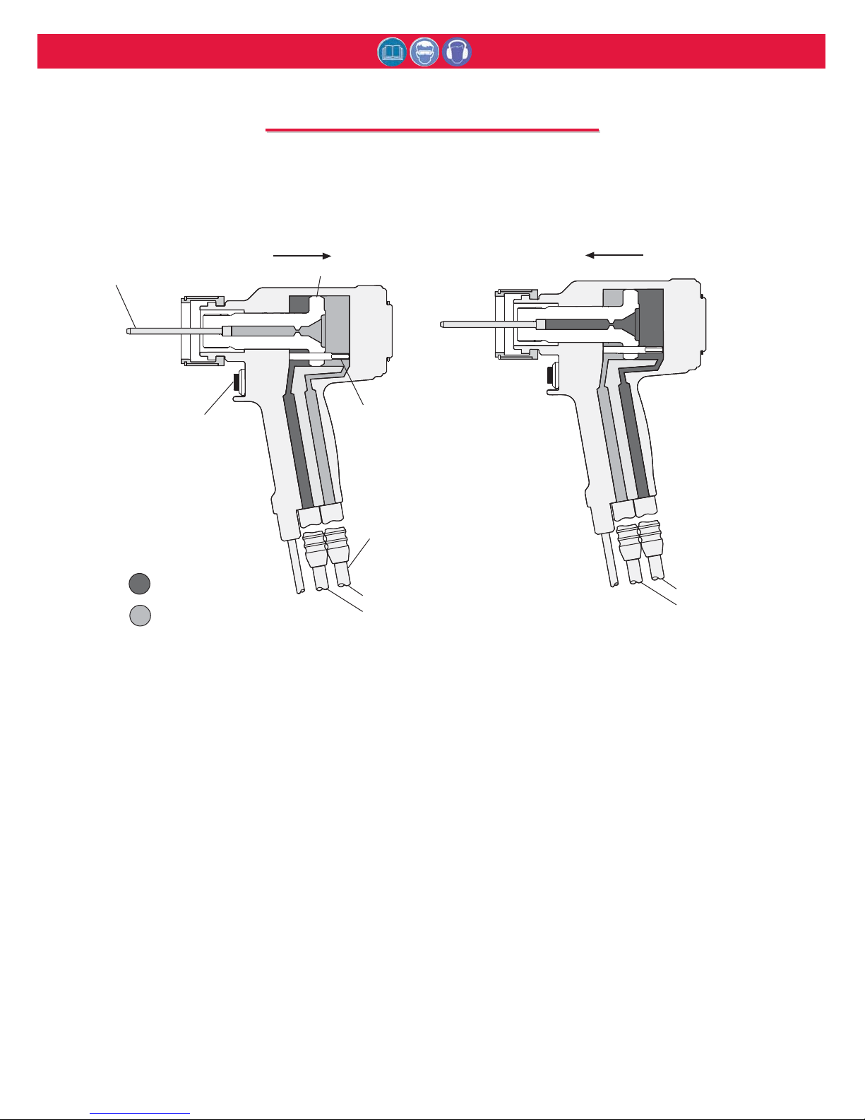
When the trigger is depressed, a solenoid
operated valve in the POWERIG® directs
pressurized hydraulic fluid through the
PULL hose to the front side of the piston,
and allows fluid on the RETURN side to
flow back to the tank (Fig 1a). The piston
and nose assembly collet moves rearward
installing the fastener. When the piston
reaches the end of the PULL stroke, it
uncovers flats on the rear end of the
unloading valve. These flats are designed
to provide a passage for hydraulic fluid
from the PULL side to the RETURN side of
the piston, “unloading” or “dumping” the
pressurized fluid back to the tank (Fig 1a).
When the trigger is released the solenoid is
de-energized and the valve directs
pressurized fluid to the rear side of the
piston and allows fluid on the PULL side to
flow back to the tank (Fig. 1b). This causes
piston and collet to move forward and
pushes the nose assembly and tool off the
swaged (installed) fastener. When the
piston reaches the end of the return stroke,
pressure is built up, causing the power rig
to shut off, completing the cycle.
Pull Pressure (Pull Cycle)
Fig. 1(a)
Return Pressure (Return Cycle)
Fig. 1(b)
PINTAIL EJECTOR
PULL PISTON
TRIGGER SWITCH
DUMP VALVE
HYDRAULIC HOSES
RETURN PRESSURE
PULL PRESSURE
RETURN PRESSURE
PULL PRESSURE
D
Pressurized Oil
Return Oil
Piston Travel Piston Travel
P
P
RINCIPLE
RINCIPLE
OF
OF
O
O
PERATION
PERATION
Page 6

2620 series Tooling (HK1012) Alcoa Fastening Systems
6
S
S
PECIFICATIONS
PECIFICATIONS
-
-
ALL
ALL
MODELS
MODELS
POWER SOURCE:
Huck POWERIG Hydraulic Unit
HOSE KITS:
Use only genuine HUCK Hose Kits rated @ 10,000
psi working pressure.
HYDRAULIC FLUID:
ATF meeting DEXRON III, DEXRON IV, MERCON,
Allison C‐4 or equivalent specifications.
Fire resistant hydraulic fluid may also be used,
and is required to comply with OSHA regulation
1926.302 paragraph (d): "the fluid used in
hydraulic power tools shall be fire resistant fluid
approved under schedule 30 of the US Bureau of
Mines, Department of Interior, and shall retain its
operating characteristics at the most extreme
temperatures to which it will be exposed."
MAX OPERATING TEMP:
125°F (51.7°C)
MAX FLOW RATE:
2 gpm (7.5 l/m)
MAX PULL PRESSURE:
7400 psi (510 bar)
PULL CAPACITY:
19,830 lbs (88.21 kN) @ 7400 psi
STROKE:
1.437 inches (3.65 cm)
WEIGHT:
9.87 lbs (4.48 kg)
Page 7

2620 series Tooling (HK1012) Alcoa Fastening Systems
7
R
34.30
1.350
7.046
178.97
1.606
40.81
2.160
54.86
ø
10.162
258.1
2.827
71.81
ø
6.270
159.27
3.836
97.43
10°
Model
2620-PT/A2620-PT
INCHES
mm
S
S
PECIFICATIONS
PECIFICATIONS
(
(
CONTINUED
CONTINUED
)
)
R
34.30
1.350
2.827
71.81
ø
2.160
54.86
ø
40.81
1.606
7.046
178.97
6.562
166.69
5.496
139.61
3.062
77.77
10°
Model
2620/A2620
INCHES
mm
Page 8
2620 series Tooling (HK1012) Alcoa Fastening Systems
8
POWER SOURCE CONNECTIONS
Coat hose fitting threads with a non-hardening
Teflon
TM
thread compound such as Slic-tite.
TM
1. Use Huck POWERIG® Hydraulic Unit, or
equivalent, that has been prepared for operation
per applicable instruction manual. Check both
PULL and RETURN pressures, and if required,
adjust to pressures given in
S
S
PECIFICATIONS
PECIFICATIONS
.
2. First, turn hydraulic unit to OFF, and then,
disconnect power supply from unit. Connect
tool's hoses to Powerig unit.
3. Connect tool's control switch electrical cord to
hydraulic unit.
4. Connect hydraulic unit to power supply. Turn
unit to ON. Hold tool trigger depressed for 30
seconds; depress trigger a few times to cycle
tool and to circulate hydraulic fluid. Observe
action of tool and check for leaks. Turn unit to
OFF.
5. Select nose assembly for fastener to be
installed. Disconnect tool's control switch
electrical cord from hydraulic unit; disconnect
unit from power supply. Attach nose assembly
to tool.
6. Reconnect hydraulic unit to power supply.
Reconnect tool's switch control cord to unit.
Check operation of nose assembly; install
fasteners in test plate of correct thickness with
proper size holes. Inspect installed fasteners. If
fasteners do not pass inspection, see
T
ROUBLESHOOTING
to locate and correct tool
malfunction.
WARNING: Be sure to connect Tool’s
hydraulic hoses to POWERIG Hydraulic
Unit before connecting Tool’s switch
control cord to unit. If not connected in
this orderand disconnected in the
reverse order
, severe personal Injury
may occur.
P
P
REPARATION
REPARATION
FOR
FOR
U
U
SE
SE
WARNING: Correct PULL and
RETURN pressures are required for
operator’s safety and for Installation
TooI’s function. Pressure Gauge T124883CE is available for checking
pressures. See Tool S
PECIFICATIONS
and Gauge Instruction Manual.
Failure to verify pressures may result
in severe personal injury.
WARNINGS:
Read full manual before using tool.
A half-hour training session with qualified
personnel is recommended before using
Huck equipment.
When operating Huck installation equipment,
always wear approved eye and ear protection.
Be sure there is adequate clearance for the
operator’s hands before proceeding.
* Slic-Tite is a registered trademark of LA-CO Industries, Inc.
* TEFLON is a registered trademark of DuPont Corp.
* LUBRIPLATE is a registered trademark of LUBRIPLATE Lubricants Co.
GOOD SERVICE PRACTICES
Sealants, Lubricants, Hydraulic Fluid &
Service Kits
• Rub Slic-Tite TEFLON thread compound, or
equivalent, on pipe threads to prevent leaks
and for ease of assembly.
• Smear LUBRIPLATE
®
* No. 130-AA, or
equivalent, on O-rings and mating surfaces to
prevent damaging O-rings on rough or sharp
surfaces. Also, increases ease of assembly.
(LUBRIPLATE in a tube, 502723).
CAUTION: Do not let disconnected hoses and
couplers contact a dirty floor. Keep harmful
material out of hydraulic fluid. Dirt in
hydraulic fluid causes valve failure In Tool
and In POWERIG Hydraulic Unit.
CAUTION: Do not use TEFLON
®
* tape on pipe
threads. Pipe threads may cause tape to shred
resulting in tool malfunction. (Slic-Tite is
available in stick form as Huck P/N 503237.)
Huck recommends that only Huck Powerig
Hydraulic Units be used as a power source
for Huck installation equipment. Hydraulic
power units that deliver high pressure for
both PULL and RETURN, AND ARE NOT
EQUIPPED WITH RELIEF VALVES ARE
SPECIFICALLY NOT RECOMMENDED AND
MAY BE DANGEROUS.
Page 9
2620 series Tooling (HK1012) Alcoa Fastening Systems
9
TO INSTALL A HUCKBOLT® FASTENER
1. Check work and remove excessive gap in the
space between sheets. Gap is excessive if not
enough pintail sticks through the collar for the
nose assembly jaws to grab onto.
2. Put fastener into hole.
3. Slide collar over fastener. (The beveled end of the
collar must be towards the nose assembly and
tool.)
4. Push nose assembly onto the fastener until the
nose assembly anvil stops against the collar. Tool
and nose assembly must be held at right angles
(90°) to the work.
5. Depress tool switch to start installation cycle.
6. When forward motion of nose assembly anvil
stops and pintail breaks off, release switch. Tool
will go into its return stroke, push off the installed
fastener and eject the pintail.
7. The tool and nose assembly is ready for the next
installation cycle.
O
O
PERATING
PERATING
I
I
NSTRUCTIONS
NSTRUCTIONS
WARNING: Reasonable care of installation
tools by operators is an important factor in
maintaining tool effeciency and in reducing
repair downtime. Do not abuse the tool by
dropping it, using it as a hammer, or
otherwise, causing unnecessary wear and
tear. Be sure there is adequate clearance
for the tool and operator’s hands before
proceeding. Do not connect tool’s hoses to
each other or use hoses as a handle for
carrying.
WARNING: Do not pull on a fastener
without a collar. If a fastener is pulled
without a collar, the fastener will eject
forcibly when the pintail breaks off.
S
S
ERVICING
ERVICING
THE
THE
T
T
OOL
OOL
See SS
PECIFICATIONS
PECIFICATIONS for fluid type. Dispose of fluid in
accordance with local environmental regulations. Recycle
steel, aluminum, and plastic parts in accordance with local
lawful and safe practices.
PREVENTIVE MAINTENANCE
NOTE: For supplementary information refer to
T
T
ROUBLESHOOTING
ROUBLESHOOTING, Parts Lists, and
D
D
ISASSEMBLY
ISASSEMBLY
AND
AND
A
A
SSEMBLY
SSEMBLY procedures in this manual.
SYSTEM INSPECTION
Operating efficiency of the installation tool is directly related to
performance of the complete system, including the tool with
nose assembly, hydraulic hoses, trigger and control cord, and
POWERIG. Therefore, an effective preventive maintenance
program includes scheduled inspections of the system to
detect and correct minor troubles.
1. Inspect tool and nose for external damage.
2. Verify that hydraulic hose fittings and couplings and
electrical connections are secure.
3. Inspect hydraulic hose for signs of damage or aging.
Replace hoses if damaged.
4. Inspect tool, hose, and POWERIG during operation to
detect abnormal heating, leaks, or vibration.
POWERIG MAINTENANCE
Maintenance instructions and repair procedures are in the
appropriate POWERIG Instruction Manual.
TOOL MAINTENANCE
At regular intervals, depending on use, replace all O-rings and
back-up rings in the tool. Spare Parts Kit part no. 2620KIT or
2620-PTKIT should be kept on hand. Inspect cylinder bore,
piston and piston rod and unloading valve for scored surfaces,
excessive wear or damage, and replace as necessary.
NOSE ASSEMBLY MAINTENANCE
Daily cleaning of the nose assembly is recommended. This
can usually he accomplished by dipping nose assembly in
mineral spirits, or other suitable solvent, to clean jaws and
wash away metal chips and dirt. If more thorough cleaning or
maintenance is necessary, disassemble the nose assembly.
Use a sharp pointed “pick” to remove imbedded particles from
the pull grooves of the jaws.
CAUTIONS:
- Consult MSDS before servicing tool.
- Keep dirt and other material out of
hydraulic system.
- Separated parts most be kept away
from dirty work surfaces.
- Dirt/debris in hydraulic fluid causes
Dump Valve failure in Tool and in
POWERIG® Hydraulic Unit’s valves.
- Always check tool assembly drawing
for the proper direction of the flats on
the Dump Valve.
CAUTION: Do not use TEFLON®* tape on
pipe threads. Pipe threads may cause tape
to shred resulting in tool malfunction.
(Slic-Tite is available in stick form as
Huck P/N 503237.)
CAUTION: Always replace seals, wipers,
and back-up rings when tool is
disassembled for any reason.
Page 10
2620 series Tooling (HK1012) Alcoa Fastening Systems
10
(Refer to Figures 2-4 & 8-13) For component
identification and Parts Lists refer to Figures 8-13.
NOTE: The following procedure is for complete
disassembly of tool. Disassemble only components
necessary to replace damaged O-rings, Quad-Rings,
Back-up Rings, and worn or damaged components.
Always use soft jaw vice to avoid damage to tool.
1. Disconnect electrical or air connector from Powerig.
Uncouple tool hydraulic hoses.
2. Remove nose assembly.
3. Unscrew coupling nipple and coupling body. Drain
hydraulic hoses into container. Discard fluid.
4. Push rearward on Piston (4) until remaining hydraulic
fluid is drained into container. Discard fluid.
5. NOTE: Do not remove hydraulic hoses from tool unless
replacing hoses. If it is necessary to remove hoses,
uncover hose fittings by sliding plastic shrouds back.
6. NOTE: Use the following steps only if the switch, wire
or connector needs repair.
2620, 2620-PT Models Only
Remove Retaining Nut and Locking ferrule from Strain
Relief (20). Loosen setscrew (37) and remove switch
(21). Loosen and remove the two wires from the switch.
Remove cord from tool. Disassemble electrical
connector (110686) (Figs. 8, 9, & 12).
A2620, A2620-PT Models Only
Unscrew and remove Air Switch (21). Remove
Retaining Nut and Locking ferrule from Air Fitting (20).
Remove plastic tubing and unscrew remaining part of
fitting (20) from handle (Fig. 10,11&13).
7. Standard Models:
(Fig. 8 & 10)
Remove Retaining Ring (17), cover plate (16) and
Locking Disk (18).
2620-PT Model:
(Fig. 9 & 11)
Remove Deflector (32), Screws (31), Barbed Retainer
(30) and locking disk (18).
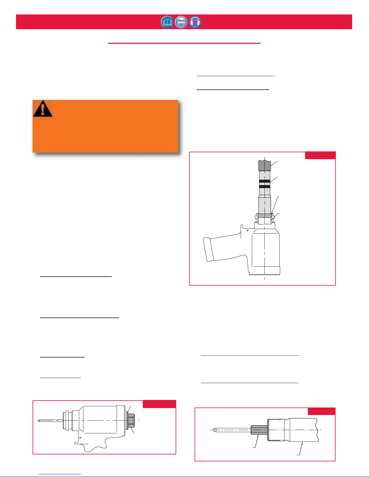
8. Insert hex key in End Cap (15) as shown in Figure 2.
Using a wrench unscrew end cap from cylinder.
9. Standard Models: (Fig. 8 & 10)
Remove O-ring (9) and Back-up Ring (8)
2620-PT Model: (Fig.9 & 11)
Remove O-ring (9), Back-up Ring (8), retaining ring
(36), washer (35), polyseal (34) and wiper seal (33).
10. Remove Dump Valve (19) from rear of cylinder.
11. Slide Spacer (123112-6/7) over piston and thread on
Piston Assembly Tool (123111-6/7). Using a press
push front gland and piston assemblies out of the
back of the cylinder. (Fig. 3)
12. Remove Piston Assembly Tool (123111-6/7) and
Spacer (123112-6/7) (Fig.3).
13. Slide Front Gland (11) off of Piston (4) and remove
Wiper (6), Wiper Housing (7), Back-up Ring (8), Oring (9) and Polyseal (10) (Fig. 8 - 11).
14. Remove GLYD Ring (13) from Piston (4) (Fig. 5).
15. Standard Models Only: (Fig. 4, 8 & 10)
Hold Piston (4) in a vise with soft jaws and remove
Ejector Gland Assembly (22) with Hex Key 122048
16. Standard Models Only: (Fig. 4, 8 & 10)
Remove from gland, Ejector Rod (29), Washer (23),
O-rings (24), Wiper (26) Quad-Ring (28) and Back-up
Ring (27).
HEX KEY
124434-1
(2620 & 2620-PT)
15
Figure 2
PRESS
SPACER
123112-6
(2620 & 2620-PT)
PISTON
PISTON ASSEMBLY TOOL
123111-6
(2620 & 2620-PT)
Figure 3
D
D
ISASSEMBLY
ISASSEMBLY
-
-
ALL
ALL
MODELS
MODELS
WARNING: Be sure to disconnect tool's
electric control trigger system from
Hydraulic Unit before disconnecting tool's
hoses from unit. Before any maintenance
is done, DISCONNECT IN THIS ORDER
(RECONNECT IN THE OPPOSITE ORDER)
to avoid possible severe personal injury.
122048 HEX KEY
PISTON
Figure 4
Page 11
2620 series Tooling (HK1012) Alcoa Fastening Systems
11
(Refer to Figures 2, 4, 5, & 8-13) For component
identification and Parts Lists, refer to Figures 8-11.
NOTE: Clean components with mineral spirits, or similar
solvent. Inspect for wear/damage and replace as
necessary. Replace all seals of disassembled components.
Use O-rings, Quad-Rings and Back-up Rings in Service
Parts Kit 2620KIT and 2620-PTKIT. Smear LUBRIPLATE
130AA or PARKER-O-LUBE on O-rings, Quad-Rings,
Back-up Rings and mating parts to ease assembly.
Assemble tool taking care not to damage O-rings, QuadRings, or Back-up Rings.
1. Standard Models Only: (Fig. 8 & 10)
Install Back-up
Ring (27), Quad-Ring (28), Wiper (26), O-rings (24),
Washer (23) and Ejector Rod (29) into Ejector Gland
(25).
2. Standard Models Only: (Fig. 4, 8 & 10)
Hold Piston
(4) in a vise with soft jaws and install assembled Ejector
Gland (22). Use Hex Key 122048 to tighten.
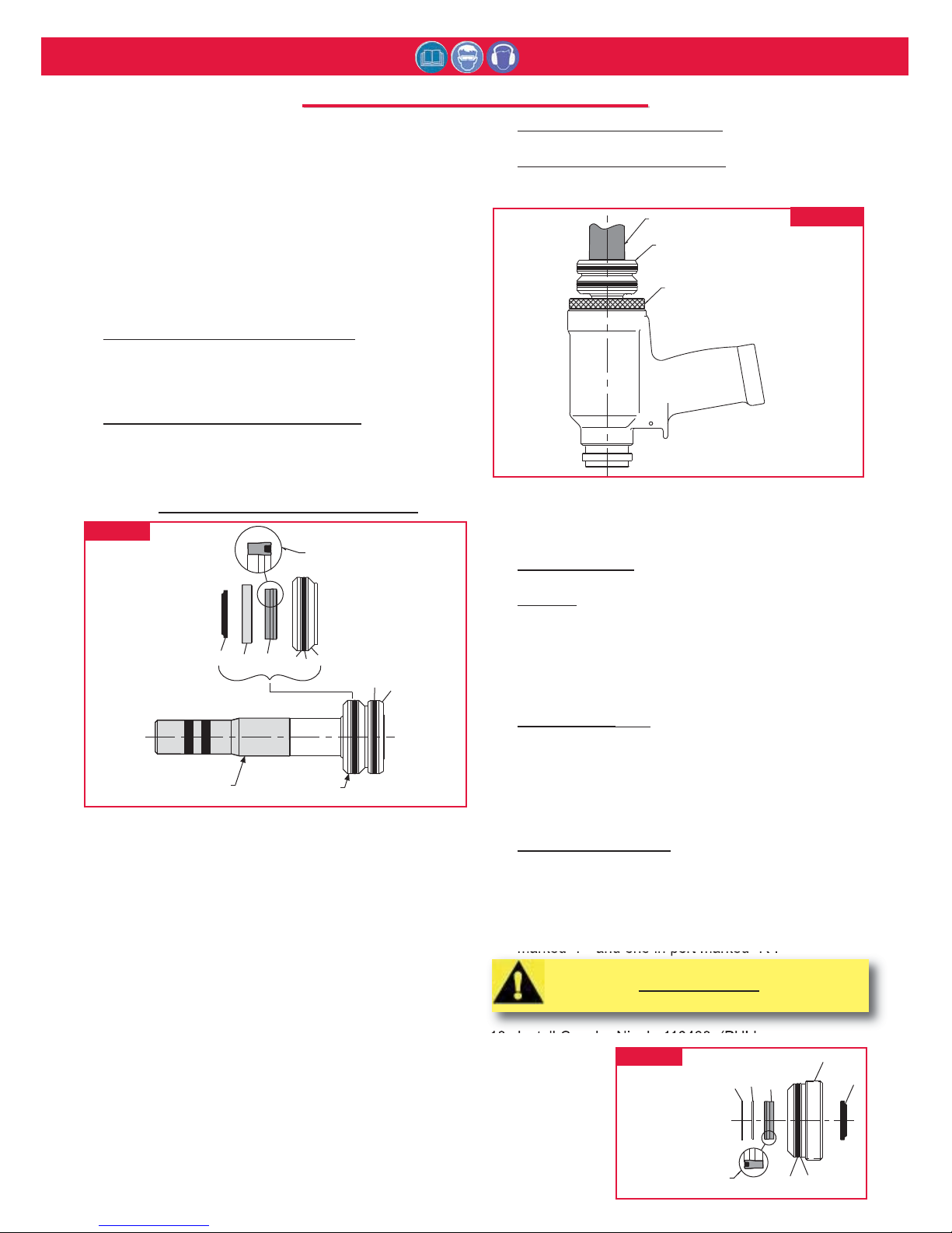
3. Thread Piston Assy Tool (123111-6/7), onto Piston (4)
(Fig. 5). Note:
Do not install spacer 123112-6/7.
4. Install GLYD Ring (13) onto Piston (4).
5. Install Polyseal (10), O-ring (9), Back-up Ring (8),
Wiper Housing (7) and Wiper (6) into Front Gland (11).
6. Lubricate Piston Assembly Tool and Piston, then slide
assembled Gland (11) over Piston Assembly Tool onto
Piston.
7. Thread GLYD Ring Insertion Tool (121694-2620) into
the back of the Cylinder (Fig. 6).
8. Using a press, push Piston and Front Gland
Assemblies into the back of Cylinder (5). (Fig. 6)
9. Remove Piston Assembly Tool (123111-6/7).
10. Remove the GLYD Ring Insertion Tool (121694-2620)
from the back of the Cylinder (Fig.6).
11. From rear of Cylinder, install Dump Valve (19) with the
four flats facing the rear of the tool (Figs. 8-11).
12. Standard Models: (Fig. 8 & 10)
Install O-ring (9) and
Back-up Ring (8) on End Cap (15).
2620-PT Model: (Fig.7, 9 & 11)
Install Back-up Ring
(8), O-ring (9), Wiper (33), Polyseal (34), Washer (35)
and Retaining Ring (36) into End Cap (15).
13. Insert Hex Key into the End Cap (15). Using a
wrench thread the End Cap into the back of the
Cylinder and tighten (Fig. 2).
14. Standard Models:
(Fig. 8 & 10) Install Locking Disk
(18), Cover Plate (16) and Retaining Ring (17).
2620-PT: (Fig. 9 & 11) Install Locking Disk (18),
Barbed Retainer (30), Screws (31) and Deflector (32).
15. If removed, reinstall Electrical/Air Connector.
16. NOTE: If switch or wire have been removed, replace
as follows:
2620, 2620-PT
Only Slide Retaining Nut and Ferrule
onto Electrical Wire. Feed Wire through Handle and
pull out through Trigger Switch hole. Attach Wires to
Switch (21) and push assembly back into Handle.
Tighten Screw (37) to hold Trigger Switch in place.
Slide Ferrule into Strain Relief Housing, then thread
and tighten Retaining Nut (Fig. 12).
A2620, A2620-PT
Only Install fitting (20) into handle.
Slide retaining nut and ferrule over plastic tubing.
Slide tubing into fitting (20) and tighten retaining nut.
Screw in air trigger (21) and tighten(Fig. 13).
17. If removed, install one hydraulic Hose in Handle port
marked "P" and one in port marked “R”.
18. Install Coupler Nipple 110438, (PULL pressure
hose); Coupler
Body,
(RETURN
pressure
hose)
(Fig. 12 & 13).
33
15
34
35
36
98
SECTION SHOWING
POLYSEAL DIRECTION
Figure 7
A
A
SSEMBLY
SSEMBLY
-
-
ALL
ALL
MODELS
MODELS
6
SECTION SHOWING
POLYSEAL DIRECTION
7
10
8
9
11
4
13
FRONT GLAND
ASSEMBLY
PISTON ASSEMBLY TOOL
123111-6 (2620 & 2620-PT)
Figure 5
PRESS
PISTON, FRONT GLAND
AND PISTON ASSEMBLY
TOOL
GLYD RING INSERTION TOOL
121694-2620 (2620 & 2620-PT
All Models)
Figure 6
CAUTION: Do not use Teflon tape on pipe
threads. See S
ERVICING THE TOOL section of this
manual.
Page 12
2620 series Tooling (HK1012) Alcoa Fastening Systems
12
37
37
21
20
19
18
89
15
13
12
11
1098765
432
1
16
17
29
22
23
24
25
28
24
27
26
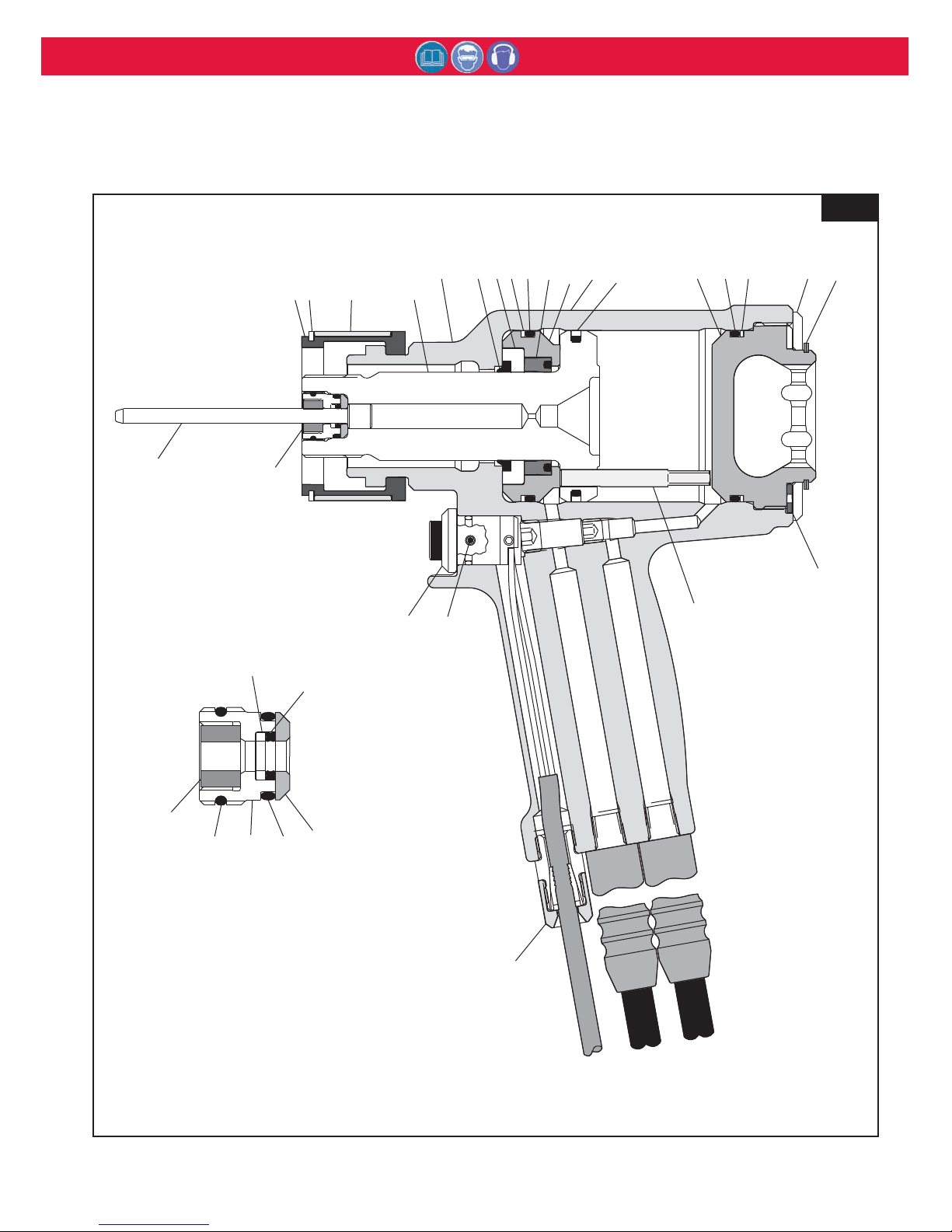
22 EJECTOR
GLAND ASSEMBLY
FIG 8
A
A
SSEMBLY
SSEMBLY
D
D
RAWING
RAWING
2620 & 2620-15
2620 & 2620-15
Model
2620 & 2620-15
Page 13
2620 series Tooling (HK1012) Alcoa Fastening Systems
13
37
37
21
20
19
36
35
34
18
33
32
3130
8
9
15
14
131211
10
9
8
7
65
4321
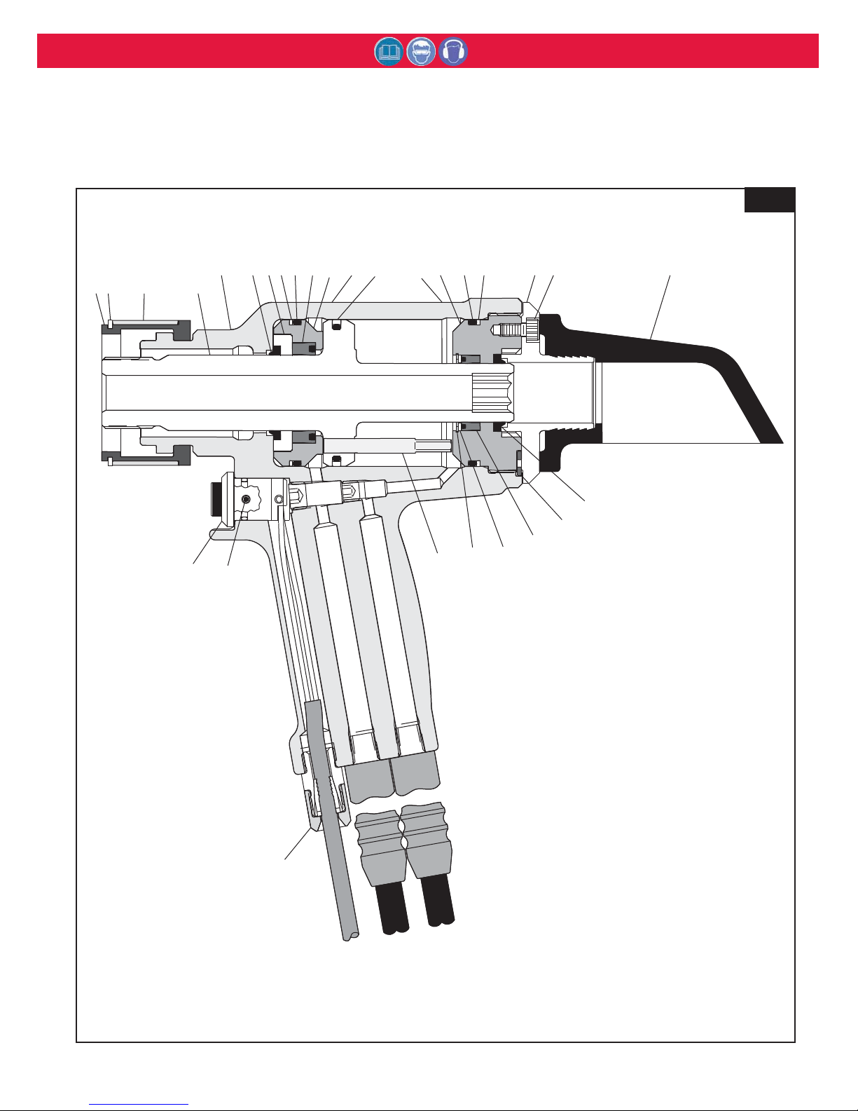
FIG 9
A
A
SSEMBLY
SSEMBLY
D
D
RAWING
RAWING
2620-PT & 2620-PT-15
2620-PT & 2620-PT-15
Model
2620-PT & 2620-PT-15
Page 14
2620 series Tooling (HK1012) Alcoa Fastening Systems
14
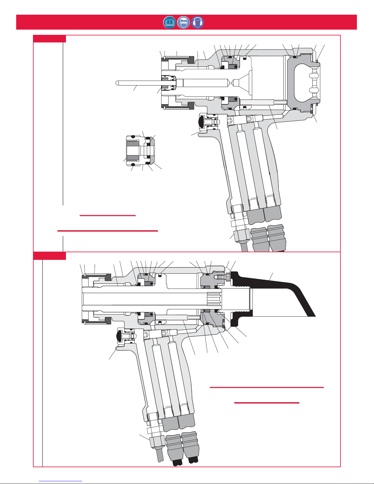
Figure 10
A
A
SSEMBLY
SSEMBLY
D
D
RAWING
RAWING
A2620
A2620
Figure 11
A
A
SSEMBLY
SSEMBLY
D
D
RAWING
RAWING
A2620-PT
A2620-PT
29
27
26
25
24
22
EJECTOR
GLAND ASSEMBLY
24
22
28
7
1
2
21
23
6
5
43
1098
13
12
11
15
19
89
16
17
18
21
10
8
65
7
4321
9
20
9
14
15
19
36
131211
8
3130
33
18
34
35
32
20
Page 15
2620 series Tooling (HK1012) Alcoa Fastening Systems
15
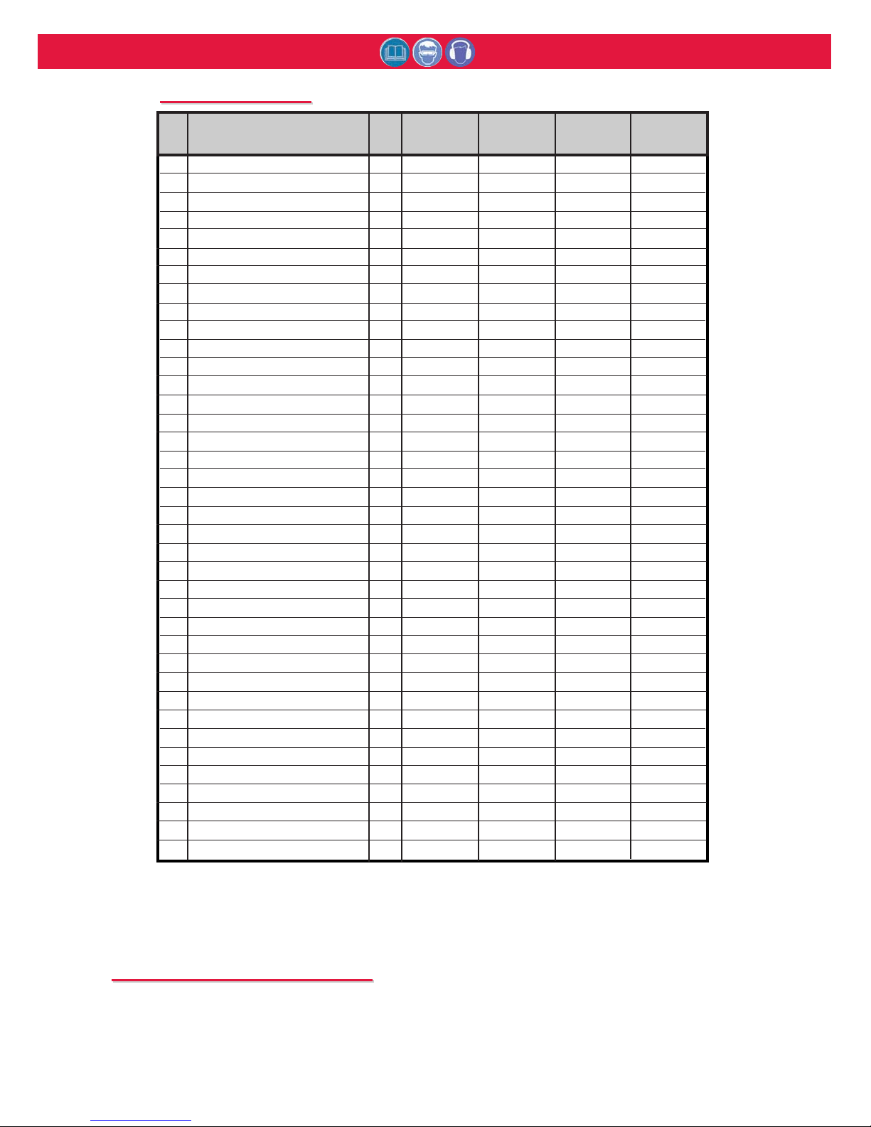
1 Split Ring 1 102147 102147 102147 102147
2 Retaining Ring 1 501514 501514 501514 501514
3 Retaining Sleeve 1 102148 102148 102148 102148
4 Piston 1 125612* 125612* 125761** 125761**
5 Cylinder Assembly 1 126152 126152 126152 126152
6 Wiper Seal 1 507407 507407 507407 507407
7 Wiper Housing 1 125610 125610 125610 125610
8 Back-up Ring 2 501127 501127 501127 501127
9 O-ring 2 507412 507412 507412 507412
10 Polyseal 1 507408 507408 507408 507408
11 Front Gland 1 125609 125609 125609 125609
12 HUCK Sticker 1 590517 590517 590517 590517
13 GLYD Ring Assembly 1 122769-1 122769-1 122769-1 122769-1
14 CE & Warning Sticker 1 590424-7400 590424-7400 590424-7400 590424-7400
15 End Cap 1 125614 125614 125763 125763
16 Cover Plate 1 125617 125617 ------------ -----------17 Retaining Ring 1 507406 507406 ------------ -----------18 Locking Disc 1 122764 122764 122764 122764
19 Dump Valve 1 125616 125616 125616 125616
20 Strain Relief or Air Fitting 1 505344 503902 505344 503902
21 Trigger Switch Assembly 1 120361 119345-1 120361 119345-1
22 Ejector Gland Assembly 1 120653 120653 ------------ -----------23 Ejector Washer 1 120652 120652 ------------ -----------24 O-ring 2 500779 500779 ------------ -----------25 Gland 1 122047 122047 ------------ -----------26 Rod Wiper 1 122742 122742 ------------ -----------27 Back-up Ring 1 501080 501080 ------------ -----------28 Quad-Ring 1 501411 501411 ------------ -----------29 Pintail Ejector 1 122705 122705 ------------ -----------30 Barbed Retainer 1 ------------ ------------ 125765 125765
31 Screws 3 ------------ ------------ 500060 500060
32 Deflector 1 ------------ ------------ 122766 122766
33 Wiper Seal 1 ------------ ------------ 505894 505894
34 Polyseal 1 ------------ ------------ 506160 506160
35 Spacer 1 ------------ ------------ 122762 122762
36 Retaining Ring 1 ------------ ------------ 506159 506159
37 Set Screw 1 501731 501731 501731 501731
Item Description Qty
2620 A2620 2620-PT A2620-PT
2620-15 2620-PT-15
P
P
ARTS
ARTS
L
L
IST
IST (Figures 1, 2A, 2B, and 2C)
* Piston 125612 is not sold separately. It may be
purchased as Piston Assembly part no. 125613,
which contains Piston 125612 and GLYD Ring
Assembly 122769-1.
** Piston 125761 is not sold separately. It may be
purchased as Piston Assembly part no. 125762,
which contains Piston 125761 and GLYD Ring
Assembly 122769-1.
S
S
TICKER
TICKER
L
L
OCATIONS
OCATIONS
The 2620 series tools come labeled with Sticker part number 590424-7400, which contains safety and
pressure settings information. It is necessary that this sticker remain on the tool and is easily read. If
sticker becomes damaged or worn, or if it have been removed from the tool, or when replacing
Cylinder, this sticker must be ordered and placed in the location shown. Sticker locations and part
numbers may be found in Figure 6 and Parts List.
Page 16
2620 series Tooling (HK1012) Alcoa Fastening Systems
16
MALE CORD
CONNECTOR
110686
502298 REDUCING BUSHING (2)
110438 MALE CONNECTOR
110439 FEMALE CONNECTOR
HOSE ASSEMBLY (2)
(SEE TABLE)
CONTROL CORD
(SEE TABLE)
505839 CABLE TIE
HOSE ASSEMBLY
MODEL(S) CONTROL CORD
123337-1126107-1
2620, 2620PT
MODEL SELECTION
123336
126107-2
2620-15, 2620-PT-15
FIG 12
H
OSE
A
SSEMBLY
F
OR
E
LECTRIC
T
RIGGER
M
ODELS
Page 17
2620 series Tooling (HK1012) Alcoa Fastening Systems
17
126107-2
Hose (2)
110439 Female
Connector
110438 Male
Connector
502298 Reducing
Bushing (2)
A2620
119440-3 Air Trigger
and Hose Assembly
A2620-PT
119440-1 Air Trigger
and Hose Assembly
A2620
112143-3 Air Hose
A2620-PT
112143 Air Hose
113021
Air Fitting
503902
Air Fitting
120770 Hose
Sleeving
H
OSE
A
SSEMBLY
F
OR
A
IR
T
RIGGER
M
ODELS
FIG 13
Page 18

2620 series Tooling (HK1012) Alcoa Fastening Systems
18
T
T
ROUBLESHOOTING
ROUBLESHOOTING
Always check the simplest possible cause of a
malfunction first. For example, a loose or disconnected
trigger line. Then proceed logically and eliminate each
possible cause until the defect is found. Where possible,
substitute known good parts for suspected defective
parts. Use the following steps as an aid in
troubleshooting.
1. Tool fails to operate when trigger is pressed.
a. Inoperative POWERIG® Hydraulic Unit. See
applicable instruction manual.
b. Loose electrical connections.
c. Damaged trigger assembly.
d. Loose or faulty hose coupling.
2. Tool operates in reverse.
a. Reversed hose connections between hydraulic
unit and tool.
3. Tool leaks hydraulic fluid.
a. Defective tool O-rings or loose connections at tool.
4. Hydraulic couplers leak fluid.
a. Damaged or worn O-rings in Coupler Body
Coupler P/N 110440.
5. Hydraulic fluid overheats.
a. Unit not operating properly - - see units manual.
b. Unit running in reverse (918; 918-5 only) - - see
units manual.
6. Tool operates erratically and fails to install fastener
properly.
a. Low or erratic hydraulic pressure - - air in system.
b. Damaged or worn Piston O-ring in tool.
c. Excessive wear on sliding surfaces of tool parts.
7. Pull grooves on fastener pintail stripped during PULL
stroke.
a. Operator not sliding anvil completely onto fastener
pintail.
b. Incorrect fastener grip.
c. Worn or damaged jaw segments.
d. Metal particles in jaw grooves.
e. Excessive sheet gap.
8. Collar of fastener not completely swaged.
a. Improper tool operation - - see No. 6.
b. Scored anvil.
9. Tool "hangs up" on swaged collar of fastener.
a. Improper tool operation - - see No. 6.
b. RETURN pressure too low.
c. Not enough collar lubricant.
d. Nose assembly not installed per NOSE
ASSEMBLY DATA SHEET.
10. Pintail of fastener fails to break.
a. Improper tool operation - - see No. 6.
b. Pull grooves on fastener stripped - - see No. 7.
c. PULL pressure too low.
11. Nose will not release broken pintail.
a. Nose assembly not installed per NOSE
ASSEMBLY DATA SHEET.
K
K
ITS
ITS
AND
AND
A
A
CCESSORIES
CCESSORIES
Service Kits:
2620/A2620 - 2620KIT
2620-PT/A2620-PT - 2620-PTKIT
Assembly Tool Kits:
2620/A2620 &
2620-PT/A2620-PT Tool Kit - 123110-7
Includes: (Fig. 3 & 6))
Spacer - 123112-6
Piston Assembly Tool - 123111-6
GLYD Ring Insertion Tool - 121694-2620
Accessories:
Ejector Hex Wrench (All Models) - 122048
End Cap Hex Wrench
2620 & 2620-PT - 124434-1
2620-PT/A2620-PT - 124434-1
Remote Trigger (All Models) - 123381-24
Page 19

2620 series Tooling (HK1012) Alcoa Fastening Systems
19
L
L
IMITED
IMITED
W
W
ARRANTIES
ARRANTIES
TOOLING WARRANTY:
Huck warrants that tooling and other items (excluding
fasteners, and hereinafter referred as "other items")
manufactured by Huck shall be free from defects in
workmanship and materials for a period of ninety (90)
days from the date of original purchase.
WARRANTY ON "NON STANDARD OR CUSTOM
MANUFACTURED PRODUCTS":
With regard to non-standard products or custom
manufactured products to customer's specifications,
Huck warrants for a period of ninety (90) days from
the date of purchase that such products shall meet
Buyer's specifications, be free of defects in
workmanship and materials. Such warranty shall not
be effective with respect to non-standard or custom
products manufactured using buyer-supplied molds,
material, tooling and fixtures that are not in good
condition or repair and suitable for their intended
purpose.
THERE ARE NO WARRANTIES WHICH EXTEND
BEYOND THE DESCRIPTION ON THE FACE
HEREOF. HUCK MAKES NO OTHER
WARRANTIES AND EXPRESSLY DISCLAIMS ANY
OTHER WARRANTIES, INCLUDING IMPLIED
WARRANTIES AS TO MERCHANTABILITY OR AS
TO THE FITNESS OF THE TOOLING, OTHER
ITEMS, NONSTANDARD OR CUSTOM
MANUFACTURED PRODUCTS FOR ANY
PARTICULAR PURPOSE AND HUCK SHALL NOT
BE LIABLE FOR ANY LOSS OR DAMAGE,
DIRECTLY OR INDIRECTLY, ARISING FROM THE
USE OF SUCH TOOLING, OTHER ITEMS,
NONSTANDARD OR CUSTOM MANUFACTURED
PRODUCTS OR BREACH OF WARRANTY OR FOR
ANY CLAIM FOR INCIDENTAL OR
CONSEQUENTIAL DAMAGES.
Huck's sole liability and Buyer's exclusive remedy for
any breach of warranty shall be limited, at Huck's
option, to replacement or repair, at FOB Huck's plant,
of Huck manufactured tooling, other items,
nonstandard or custom products found to be defective
in specifications, workmanship and materials not
otherwise the direct or indirect cause of Buyer
supplied molds, material, tooling or fixtures. Buyer
shall give Huck written notice of claims for defects
within the ninety (90) day warranty period for tooling,
other items, nonstandard or custom products
described above and Huck shall inspect products for
which such claim is made.
TOOLING, PART(S) AND OTHER ITEMS NOT
MANUFACTURED BY HUCK:
HUCK MAKES NO WARRANTY WITH RESPECT
TO THE TOOLING, PART(S) OR OTHER ITEMS
MANUFACTURED BY THIRD PARTIES. HUCK
EXPRESSLY DISCLAIMS ANY WARRANTY
EXPRESSED OR IMPLIED, AS TO THE
CONDITION, DESIGN, OPERATION,
MERCHANTABILITY OR FITNESS FOR USE OF
ANY TOOL, PART(S), OR OTHER ITEMS THEREOF
NOT MANUFACTURED BY HUCK. HUCK SHALL
NOT BE LIABLE FOR ANY LOSS OR DAMAGE,
DIRECTLY OR INDIRECTLY, ARISING FROM THE
USE OF SUCH TOOLING, PART(S) OR OTHER
ITEMS OR BREACH OF WARRANTY OR FOR ANY
CLAIM FOR INCIDENTAL OR CONSEQUENTIAL
DAMAGES.
The only warranties made with respect to such tool,
part(s) or other items thereof are those made by the
manufacturer thereof and Huck agrees to cooperate
with Buyer in enforcing such warranties when such
action is necessary.
Huck shall not be liable for any loss or damage
resulting from delays or nonfulfillment of orders owing
to strikes, fires, accidents, transportation companies
or for any reason or reasons beyond the control of the
Huck or its suppliers.
HUCK INSTALLATION EQUIPMENT:
Huck International, Inc. reserves the right to make
changes in specifications and design and to
discontinue models without notice.
Huck Installation Equipment should be serviced by
trained service technicians only.
Always give the Serial Number of the equipment
when corresponding or ordering service parts.
Complete repair facilities are maintained by Huck
International, Inc. Please contact one of the offices
listed below.
Eastern
One Corporate Drive Kingston, New York 12401-0250
Telephone (845) 331-7300 FAX (845) 334-7333
Outside USA and Canada
Contact your nearest Huck International Office, see
back cover.
In addition to the above repair facilities, there are
Authorized Tool Service Centers (ATSC's) located
throughout the United States. These service centers
offer repair services, spare parts, Service Parts Kits,
Service Tools Kits and Nose Assemblies. Please
contact your Huck Representative or the nearest
Huck office listed on the back cover for the ATSC in
your area.
Page 20

251 Cree Crescent, Winnipeg, MB Canada R3J 3X4
Tel: 204 837 8361 • 1 800 563 1293
Fax: 204 837 3520 • 1 800 974 1494
applifast.com
 Loading...