

Page 1
M
M
OODDEEL
L
55007
7
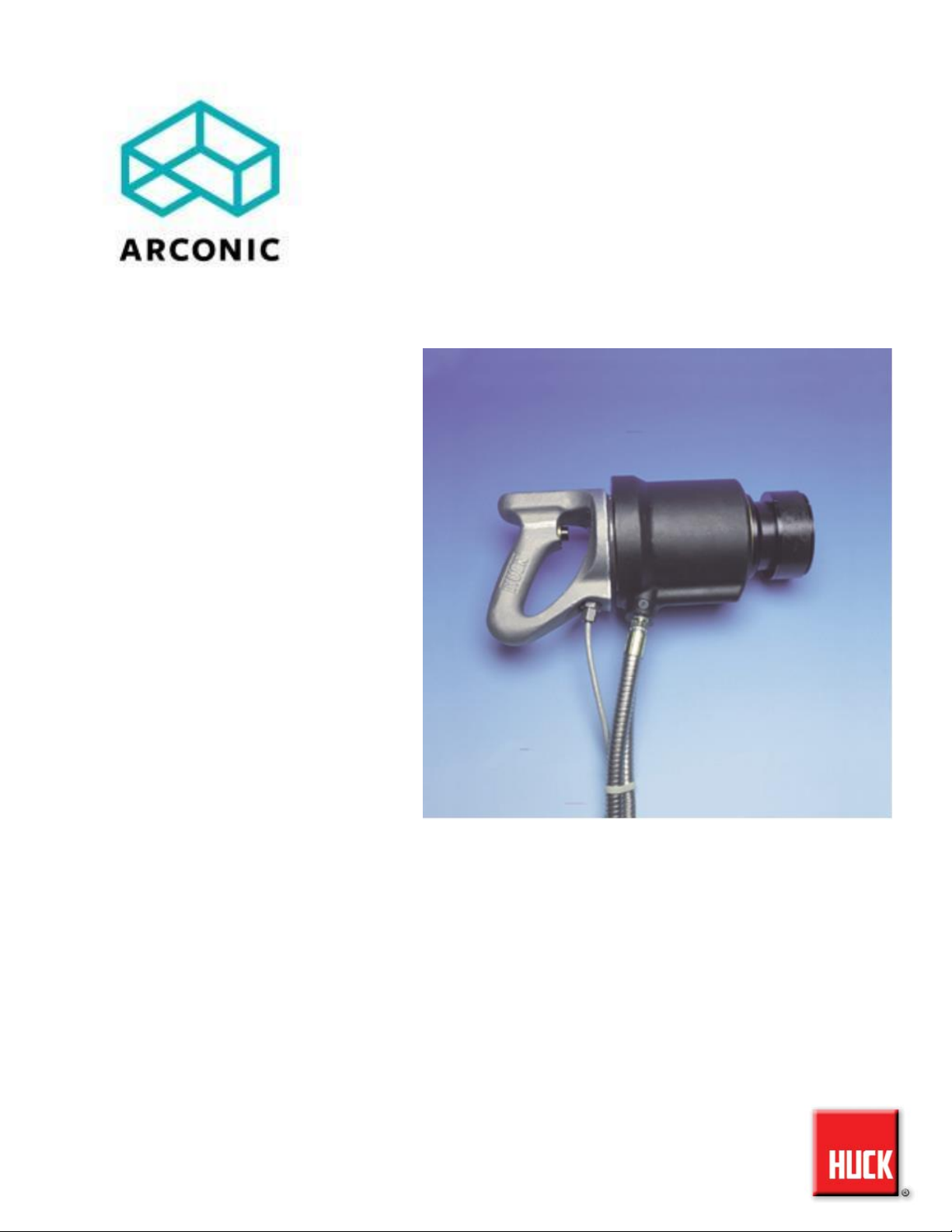
HYDRAULIC INSTALLATION TOOL
INSTRUCTION MANUAL
12-27-2013
HK480
Page 2
507
HYDRAULIC INSTALLATION TOOL
(HK480)
Arconic
2
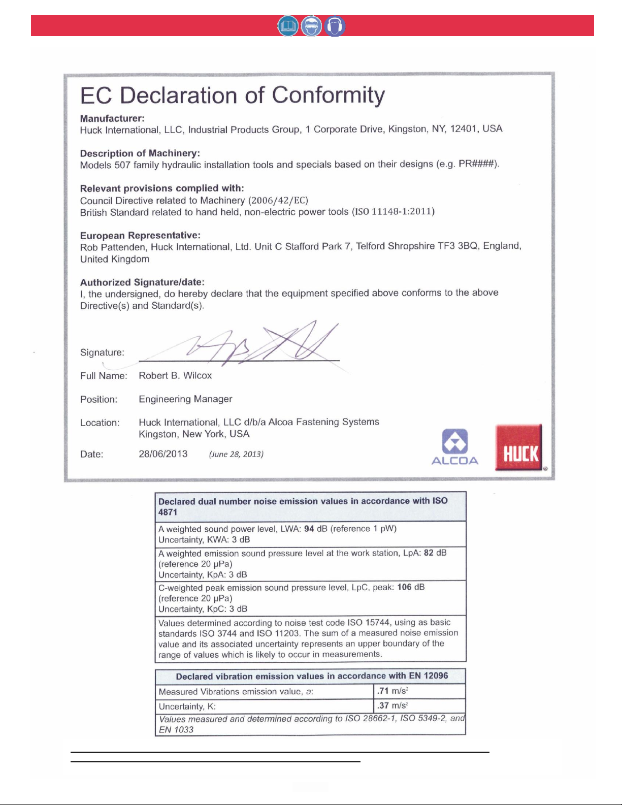
Test data to support the above information is on file at Huck International, Inc., Kingston, NY, USA. Vibration
Measurements are frequency weighted in accordance with ISO 8041 (1990).
Page 3

507
HYDRAULIC INSTALLATION TOOL
(HK480)
Arconic
3
C
C
OONNTTEENNTTS
S
EC Declaration of Conformity . . . . . . . . . . . . . . . . . . . . .
2
Safety . . . . . . . . . . . . . . . . . . . . . . . . . . . . . . . . . . . . . . . . .
4
Description . . . . . . . . . . . . . . . . . . . . . . . . . . . . . . . . . . . . .
5
Specifications . . . . . . . . . . . . . . . . . . . . . . . . . . . . . . . . . . .
5
Principle of Operation . . . . . . . . . . . . . . . . . . . . . . . . . . . .
6
Preparation for Use . . . . . . . . . . . . . . . . . . . . . . . . . . . . . .
7
Operating Instructions . . . . . . . . . . . . . . . . . . . . . . . . . . .
8
Kits and Accessories . . . . . . . . . . . . . . . . . . . . . . . . . . . . .
9
Hydraulic Couplings . . . . . . . . . . . . . . . . . . . . . . . . . . . . .
9
Maintenance . . . . . . . . . . . . . . . . . . . . . . . . . . . . . . . . . . .
10
Retrofit of Earlier Tools . . . . . . . . . . . . . . . . . . . . . . . . . .
10
Disassembly and Assembly . . . . . . . . . . . . . . . . . . . . . . .11-12
Assembly Drawing with Part Numbers . . . . . . . . . . . . . . 13
Troubleshooting . . . . . . . . . . . . . . . . . . . . . . . . . . . . . . . . . 14
Page 4
507
HYDRAULIC INSTALLATION TOOL
(HK480)
Arconic
4
Notes: are reminders of required procedures.
S
S
AAFFEETTY
Y
I
I
NNSSTTRRUUCCTTIIOONNS
S
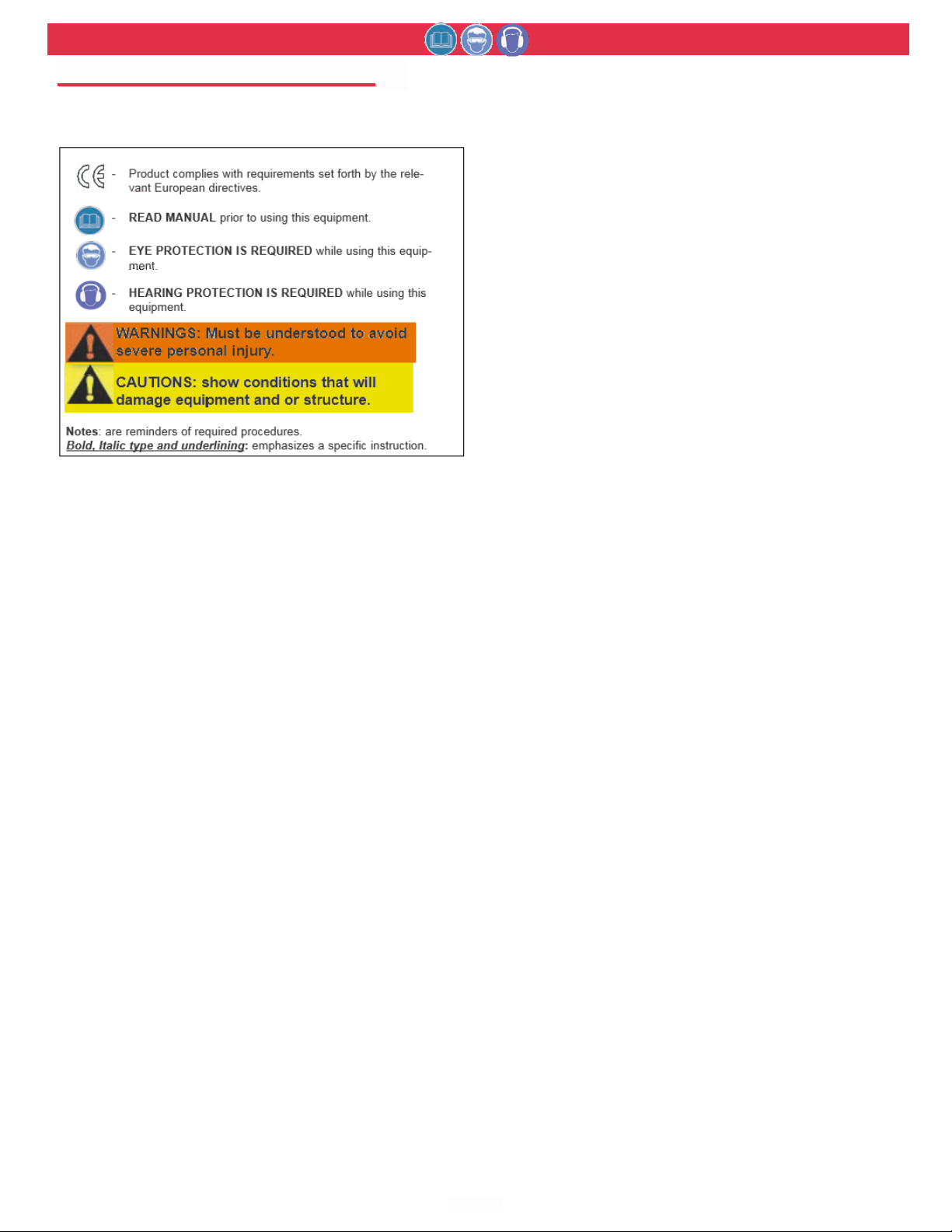
GLOSSARY OF TERMS AND SYMBOLS:
- Product complies with requirements set forth by the rele-
vant European directives.
- READ MANUAL prior to using this equipment.
- EYE PROTECTION IS REQUIRED while using this equip-
Bold, Italic type and underlining: emphasizes a specific instruction.
I. GENERAL SAFETY RULES:
1. A half hour long hands-on training session with qualified personnel is recommended before using Huck equipment.
2. Huck equipment must be maintained in a safe working condition at all times. Tools
and hoses should be inspected at the beginning of each shift/day for damage or
wear. Any repair should be done by a qualified repairman trained on Huck procedures.
3. For multiple hazards, read and understand the safety instructions before installing,
operating, repairing, maintaining, changing accessories on, or working near the
assembly power tool. Failure to do so can result in serious bodily injury.
4. Only qualified and trained operators should install, adjust or use the assembly
power tool.
5. Do not modify this assembly power tool. This can reduce effectiveness of safety
measures and increase operator risk.
6. Do not discard safety instructions; give them to the operator.
7. Do not use assembly power tool if it has been damaged.
8. Tools shall be inspected periodically to verify all ratings and markings required, and
listed in the manual, are legibly marked on the tool. The employer/operator shall
contact the manufacturer to obtain replacement marking labels when necessary.
Refer to assembly drawing and parts list for replacement.
9. Tool is only to be used as stated in this manual. Any other use is prohibited.
10. Read MSDS Specifications before servicing the tool. MSDS specifications are
available from the product manufacturer or your Huck representative.
11. Only genuine Huck parts shall be used for replacements or spares. Use of any
other parts can result in tooling damage or personal injury.
12.Never remove any safety guards or pintail deflectors.
13.Never install a fastener in free air. Personal injury from fastener ejecting may occur.
14.Where applicable, always clear spent pintail out of nose assembly before installing
the next fastener.
15.Check clearance between trigger and work piece to ensure there is no pinch point
when tool is activated. Remote triggers are available for hydraulic tooling if pinch
point is unavoidable.
16.Do not abuse tool by dropping or using it as a hammer. Never use hydraulic or air
lines as a handle or to bend or pry the tool. Reasonable care of installation tools
by operators is an important factor in maintaining tool efficiency, eliminating downtime, and preventing an accident which may cause severe personal injury.
17.Never place hands between nose assembly and work piece. Keep hands clear from
front of tool.
18.Tools with ejector rods should never be cycled with out nose assembly installed.
19.When two piece lock bolts are being used always make sure the collar orientation
is correct. See fastener data sheet for correct positioning.
II. PROJECTILE HAZARDS:
1. Risk of whipping compressed air hose if tool is pneudraulic or pneumatic.
2. Disconnect the assembly power tool from energy source when changing inserted
tools or accessories.
3. Be aware that failure of the workpiece, accessories, or the inserted tool itself can
generate high velocity projectiles.
4. Always wear impact resistant eye protection during tool operation. The grade of
protection required should be assessed for each use.
5. The risk of others should also be assessed at this time.
6. Ensure that the workpiece is securely fixed.
7. Check that the means of protection from ejection of fastener or pintail is in place
and operative.
8. There is possibility of forcible ejection of pintails or spent mandrels from front of
tool.
ment.
- HEARING PROTECTION IS REQUIRED while using this
equipment.
WARNINGS: Must be understood to avoid
severe personal injury.
CAUTIONS: show conditions that will
damage equipment and or structure.
III. OPERATING HAZARDS:
1. Use of tool can expose the operator’s hands to hazards including: crushing,
impacts, cuts, abrasions and heat. Wear suitable gloves to protect hands.
2. Operators and maintenance personnel shall be physically able to handle the bulk,
weight and power of the tool.
3. Hold the tool correctly and be ready to counteract normal or sudden movements
with both hands available.
4. Maintain a balanced body position and secure footing.
5. Release trigger or stop start device in case of interruption of energy supply.
6. Use only fluids and lubricants recommended by the manufacturer.
7. Avoid unsuitable postures, as it is likely for these not to allow counteracting of normal or unexpected tool movement.
8. If the assembly power tool is fixed to a suspension device, make sure that fixation
is secure.
9. Beware of the risk of crushing or pinching if nose equipment is not fitted.
IV. REPETITIVE MOTION HAZARDS:
1. When using assembly power tool, the operator can experience discomfort in the
hands, arms, shoulders, neck or other parts of the body.
2. When using tool, the operator should adopt a comfortable posture while maintaining a secure footing and avoid awkward or off balanced postures.
3. The operator should change posture during extended tasks to help avoid discomfort and fatigue.
4. If the operator experiences symptoms such as persistent or recurring discomfort,
pain, throbbing, aching, tingling, numbness, burning sensations or stiffness, these
warnings should not be ignored. The operator should tell the employer and consult
a qualified health professional.
V. ACCESSORIES HAZARDS:
1. Disconnect tool from energy supply before changing inserted tool or accessory.
2. Use only sizes and types of accessories and consumables that are recommended. Do not use other types or sizes of accessories or consumables.
VI. WORKPLACE HAZARDS:
1. Be aware of slippery surfaces caused by use of the tool and of trip hazards caused
by the air line or hydraulic hose.
2. Proceed with caution while in unfamiliar surroundings; there could be hidden hazards such as electricity or other utility lines.
3. The assembly power tool is not intended for use in potentially explosive environments.
4. Tool is not insulated against contact with electrical power.
5. Ensure there are no electrical cables, gas pipes, etc., which can cause a hazard if
damaged by use of the tool.
VII. NOISE HAZARDS:
1. Exposure to high noise levels can cause permanent, disabling hearing loss and
other problems such as tinnitus, therefore risk assessment and the implementation
of proper controls is essential.
2. Appropriate controls to reduce the risk may include actions such as damping materials to prevent workpiece from ‘ringing’.
3. Use hearing protection in accordance with employer’s instructions and as required
by occupational health and safety regulations.
4. Operate and maintain tool as recommended in the instruction handbook to prevent
an unnecessary increase in the noise level.
5. Select, maintain and replace the consumable / inserted tool as recommended to
prevent an unnecessary increase in noise.
6. If the power tool has a silencer, always ensure that it is in place and in good working order when the tool is being operated.
VIII. VIBRATION HAZARDS:
1. Exposure to vibration can cause disabling damage to the nerves and blood supply
to the hands and arms.
2. Wear warm clothing when working in cold conditions and keep hands warm and
dry.
3. If numbness, tingling, pain or whitening of the skin in the fingers or hands, stop
using the tool, tell your employer and consult a physician.
4. Support the weight of the tool in a stand, tensioner or balancer in order to have a
lighter grip on the tool.
X. HYDRAULIC TOOL SAFETY INSTRUCTIONS:
1. Do not exceed maximum pressure setting stated on tool.
2. Carry out a daily check for damaged or worn hoses or hydraulic connections and
replace if necessary.
3. Use only clean oil and filling equipment.
4. Power units require a free flow of air for cooling purposes and should therefore be
positioned in a well ventilated area free from hazardous fumes.
5. Ensure that couplings are clan and correctly engaged before operation.
6. Do not inspect or clean the tool while the hydraulic power source is connected.
Accidental engagement of the tool can cause serious injury.
7. Be sure all hose connections are tight.
8. Wipe all couplers clean before connecting. Failure to do so can result in damage
to the quick couplers and cause overheating.
Page 5
507
HYDRAULIC INSTALLATION TOOL
(HK480)
Arconic
5
D
D
EESSCCRRIIPPTTIIOON
N
S
S
PPEECCIIFFIICCAATTIIOONNS
S
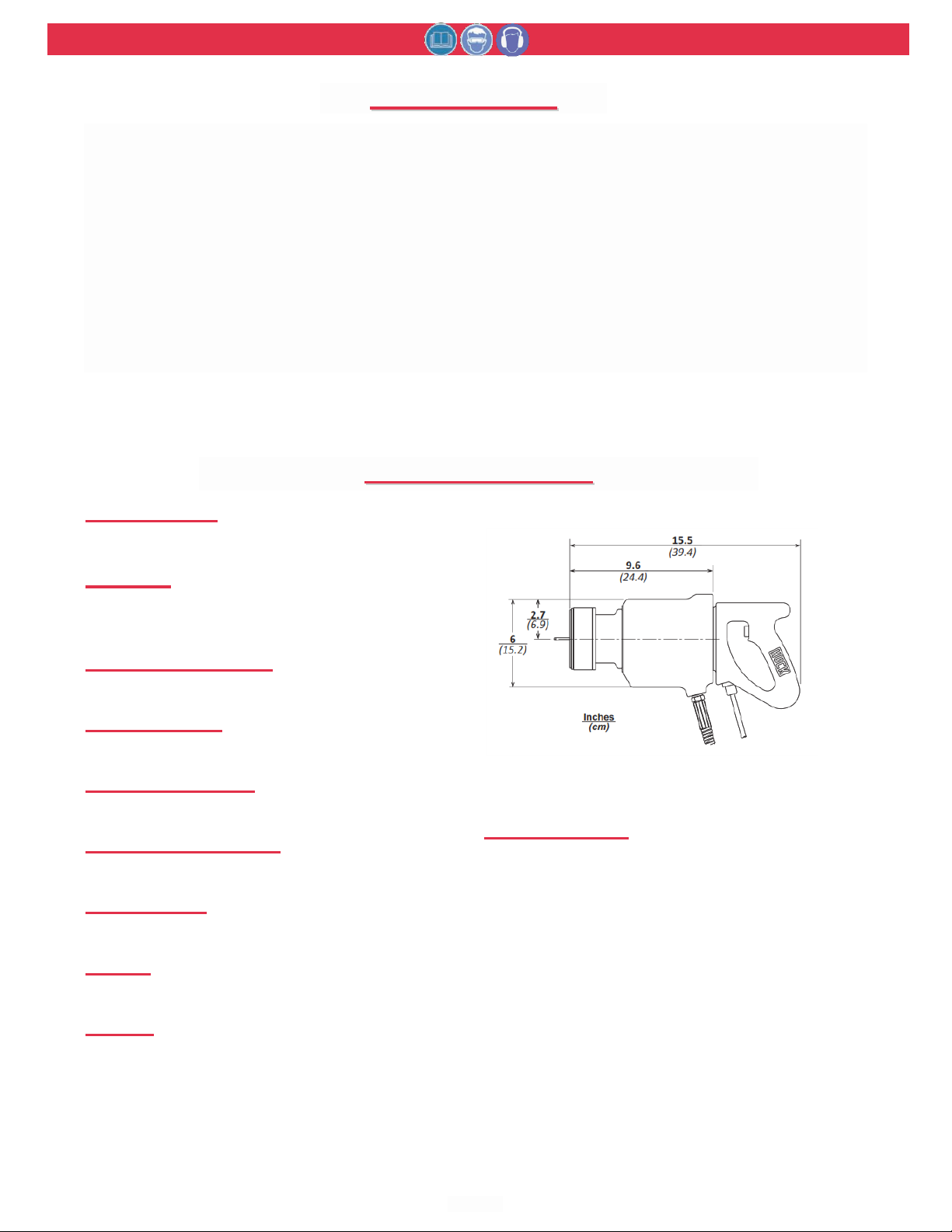
Huck Model 507 Inline Hydraulic installation Tool is
designed to install C50L HUCKBOLT® Fasteners and HLC50L
HUCKLOK® Fasteners and to operate on PULL pressure of
5400‐5700 psi (372‐393 BAR) and RETURN pressure of
2200‐2400 psi (152‐165 BAR) as supplied by Huck Hydraulic
Powerig® Models 940, 918, or equivalent.
The Model 507, when equipped with the proper Nose
Assembly, which must be purchased separately, is used to
install ‐32 (1” diameter) or ‐36 (1‐1/8 diameter) fasteners.
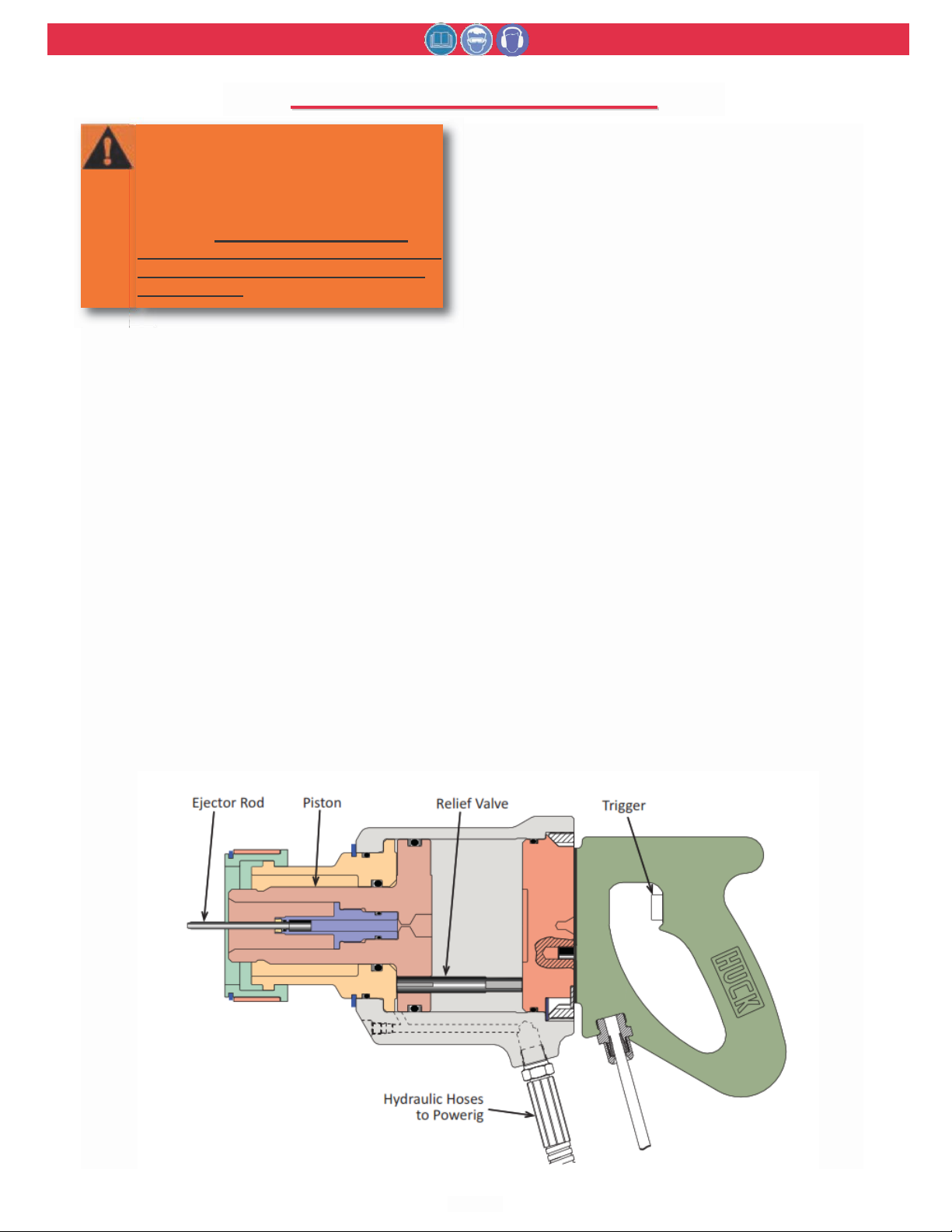
Each tool has a cylinder and piston assembly. An relief
valve, designed to relieve the hydraulic pressure at both
POWER SOURCE:
Huck POWERIG Hydraulic Unit
HOSE KITS:
Use only genuine HUCK Hose Kits rated
@ 10,000 psi working pressure.
MAX OPERATING TEMP:
125°F (51.7°C)
MAX FLOW RATE:
2 gpm (7.5 l/m)
MAX PULL PRESSURE:
5700 psi (393 bar)
MAX RETURN PRESSURE:
2400 psi (165 bar)
PULL CAPACITY:
75,700 lbs (337 kN)
STROKE:
2.5 inches (6.35 cm)
WEIGHT:
43 lbs (19.5 kg)
ends of the stroke, is positioned by the piston. A pintail
ejector is provided to eject the broken pintail from the nose
assembly. The end of the piston rod is threaded and a nose
adapter and retaining rings are included for attaching nose
assemblies.
Lengths and weights do not include Nose Assemblies.
Correct PULL and RETURN pressures are important for the
proper function of the Tool and Nose Assemblies, and for
the safety of the operator. HUCK Gage T‐124833CE is avail‐
able for checking these pressures. Instructions are furnished
with the gage and Powerig® Instruction Manuals.
HYDRAULIC FLUID:
ATF meeting DEXRON III, DEXRON IV, MERCON,
Allison C‐4 or equivalent specifications.
Fire resistant hydraulic fluid may also be used,
and is required to comply with OSHA regulation
1926.302 paragraph (d): "the fluid used in
hydraulic power tools shall be fire resistant fluid
approved under schedule 30 of the US Bureau of
Mines, Department of Interior, and shall retain its
operating characteristics at the most extreme
temperatures to which it will be exposed."
Page 6
507
HYDRAULIC INSTALLATION TOOL
(HK480)
Arconic
6
P
P
RRIINNCCIIPPLLE
E
O
O
PPEERRAATTIIOON
N
WARNING: Huck recommends that only
Huck Powerig Hydraulic Units be used
as a power source for Huck installation
equipment. Hydraulic power units that
deliver high pressure for both PULL and
RETURN, AND ARE NOT EQUIPPED
WITH RELIEF VALVES ARE SPECIFICALLY NOT RECOMMENDED AND MAY BE
DANGEROUS.
When tool hoses and cord are connected to Powerig hoses
and control cord, PULL and RETURN strokes of tool are con‐
trolled by a Trigger in the handle.
When the trigger is depressed, a solenoid operated valve in
the POWERIG directs pressured fluid through the FILL
Hydraulic Hose to the front side of piston, and allows fluid
on the RETURN side to flow back to tank.
The piston and nose assembly collet moves rearward caus‐
ing follower O‐rings and/or spring to impart a forward
motion to the follower.
If tool and nose assembly is in position on a fastener pin
and collar, this forward motion causes the jaws to clamp
onto pintail of fastener and installation cycle commences.
OOFF
When the anvil hits the sheet, continued pull causes the
pintail to break off. When the Piston reaches the end of its
PULL stroke, it uncovers flats on the rear end of the Relief
Valve. These flats were designed to provide a passage for
hydraulic fluid from PULL side to RETURN side of piston,
“unloading” or “dumping” the pressurized fluid back to
tank.
When the trigger is released, the solenoid is de‐energized
and the valve directs pressurized fluid to rear side of the
piston and allows fluid on PULL side to flow back to tank.
This causes piston and collet to move forward and pushes
nose assembly and tool off the swaged (installed) fastener.
Nose assembly jaw release contacts jaws, causing them to
open and release the broken‐off pintail. The Ejector Rod
hydraulically ejects the pintail out the front of the nose
assembly. When the piston reaches the end of its RETURN
stroke, pressure is built up causing the Powerig idler valve
(except on Models 910 and 911) to go to idling pressure.
Idling pressure keeps the tool piston and nose assembly
collet, jaws, etc. in the forward position ready for the next
installation cycle.
A flat on the front end of the relief valve was designed to
provide a passage for hydraulic fluid from RETURN side of
piston to PULL side of piston and back to tank.
Clamping pressure is applied to the sheets. The anvil is
forced forward, swaging the collar into locking grooves of
the fastener.
Page 7
507
HYDRAULIC INSTALLATION TOOL
(HK480)
Arconic
7
P
P
RREEPPAARRAATTIIOON
N
U
U
SSE
E
FFOORR
Read all WARNINGS and CAUTIONS before operating HUCK Installation Tools.
WARNINGS:
Read full manual before using tool.
A half-hour training session with qualified
personnel is recommended before using
Huck equipment.
When operating Huck installation equipment, always wear approved eye protection.
Be sure there is adequate clearance for the
operator’s hands before proceeding.
Connect Tool’s hydraulic hoses to Powerig
Hydraulic Unit before connecting Tool’s
switch control cord to unit. If not connected in this order, severe personal Injury
may occur.
Correct PULL and RETURN pressures are
required for operator’s safety and for
Installation TooI’s function. Gauge Set-Up
T-124883CE is available for checking pressures. See Tool SPECIFICATIONS and Gauge
Instruction Manual. Failure to verify pressures may result in severe personal injury.
CAUTIONS:
Do not let disconnected hoses and couplers contact a dirty floor. Keep harmful
material out of hydraulic fluid. Dirt in
hydraulic fluid causes valve failure In Tool
and In POWERIG Hydraulic Unit.
Do not use TEFLON®* tape on pipe threads.
Pipe threads may cause tape to shred
resulting in tool malfunction. (Slic-TiteTM* is
available in stick form as Huck P/N 503237.)
POWER SOURCE CONNECTIONS
Coat hose fitting threads with a non-hardening Teflon
thread compound such as Slic-tite.
(Slic-tite is available from Huck as part number
503237.)
1. Screw PULL pressure hose, part number 104490,
with coupler nipple, part number 103391, into tool
port “P.” Screw RETURN pressure hose, part num-
ber 104490, with coupler body, part number
103392, into tool port ‘‘R.’’
2. Use a Huck Powerig or equivalent that has been
prepared for operation per applicable instruction
manual. Check both PULL and RETURN pressures
and adjust as necessary. Gage part number T-
124833CE, for checking POWERIG pressures, is
available from Huck.
TM
3. Turn Powerig to “OFF” and couple tool hoses to
Powerig hoses. Be sure that the larger hoses run
from tool port “P” to POWERIG port “P” and the
smaller hoses run from tool port “R” to POWERIG
port “R”.
4. Connect trigger cord to POWERIG cord.
5. Turn POWERIG to “ON” and depress and release
trigger a few times to circulate hydraulic fluid.
Observe action of tool. Check for fluid leaks.
6. Attach the proper Nose Assembly to the tool.
TM
Hose couplers must be completely screwed
together to insure that ball checks in both
nipple and body are completely open.
Improperly assembled couplers will cause
overheating and malfunctions in both tool
and Powerig. Hand tighten couplers. Do
NOT use a pipe wrench.
NOTE: Model 507 H.I.T. with a serial number 0847
and above has a deeper pocket in the end of the
piston rod. This allows clearance for the pintail. A
longer jaw follower CAP, P/N 122686 is required in
the nose assembly. CAP, P/N 104411 is required
with previous tools.
* Slic-Tite is a registered trademark of LA-CO Industries, Inc.
* TEFLON is a registered trademark of DuPont Corp.
Page 8

507
HYDRAULIC INSTALLATION TOOL
(HK480)
Arconic
8
O
O
PPEERRAATTIINNG
G
I
I
NNSSTTRRUUCCTTIIOONNS
S
WARNINGS:
To avoid severe personal injury: Wear
approved eye and ear protection. Be sure
of adequate clearance for Operator’s
hands before proceeding with fastener
installation.
For safe operation. Please read completely
Do not pull on a pin without placing fastener/collar in a workpiece, and also, collar
chamfer MUST be out toward tool. These
conditions cause pin to eject with great
velocity and force when the pintail breaks
off or teeth/grooves strip. This may cause
severe personal injury.
Operators should receive training from
qualified personnel.
Do not bend tool to free if stuck.
Only use tool to install fasteners. NEVER
use as a jack/spreader or hammer.
CAUTIONS: Remove excess gap from
between the sheets. This permits enough
pintail to emerge from collar for ALL jaw
teeth to engage with pintail. If ALL teeth do
not engage properly, jaws will be damaged.
TO INSTALL A HUCKBOLT FASTENER:
1. Check work and remove excessive gap. (Gap is the
space between sheets. Gap is excessive if not
enough pintail sticks through the collar for the nose
assembly jaws to grab onto).
2. Put HUCKBOLT® pin in hole.
3. Slide HUCKBOLT® collar over pin. (The beveled
end of the collar must be towards the nose assembly and tool.)
4. Push nose assembly onto the pin until the nose
assembly anvil stops against the collar. Tool and
nose assembly must be held at right angles (90
degrees) to the work.
5. Depress tool trigger to start installation cycle.
6. When forward motion of nose assembly anvil stops
and pintail breaks off, release trigger. Tool will go
into its return stroke, push off the installed fastener
and eject the pintail.
7. The tool and nose assembly is ready for the next
installation cycle.
Page 9
507
HYDRAULIC INSTALLATION TOOL
(HK480)
Arconic
9
K
K
IITTS
S
A
A
CCCCEESSSSOORRIIEES
S
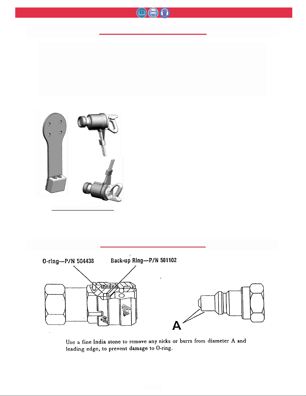
Service Kit
Includes Seals, etc for tool service.
507KIT
Hex Key, 5/16 across flats
Socket Head Screws in Handle
502446
Hex Key 3/32 across flats
Set Screw in Trigger Switch
501623
Locking Ring Wrench
Locking Ring
110362
Clamp and Bracket Kit (shown below)
Tool Hose Support
130029
H
H
YYDDRRAAUULLIIC
C
C
C
OOUUPPLLIINNGGS
S
AANNDD
DESCRIPTION USED FOR PART NO.
130029 Clamp and Bracket Kit
Page 10
507
HYDRAULIC INSTALLATION TOOL
(HK480)
Arconic
10
At regular intervals, depending on use, replace all O-
M
M
AAIINNTTEENNAANNCCE
E
PPEECCIIFFIICCAATTIIOONNS
S
T
T
RROOUUBBLLEESSHHOOOOTTIINNG
G
IISSAASSSSEEMMBBLLY
Y
AANND
D
A
A
SSSSEEMMBBLLY
Y
R
R
EETTRROOFFIIT
T
O
O
LLDDEER
R
T
T
OOOOLLS
S
CAUTIONS:
- Consult MSDS before servicing tool.
- Keep dirt and other material out of
hydraulic system.
- Separated parts most be kept away from
dirty work surfaces.
- Dirt/debris in hydraulic fluid causes
Dump Valve failure in Tool and in POWERIG® Hydraulic Unit’s valves.
- Always check tool assembly drawing for
the proper direction of the flats on the
Dump Valve.
4. Inspect tool, hose, and POWERIG during operation to detect abnormal heating, leaks, or vibration.
POWERIG Maintenance
Maintenance instructions and repair procedures are in
the appropriate POWERIG Instruction Manual.
Tool Maintenance
See SS
in accordance with local environmental regulations.
Recycle steel, aluminum, and plastic parts in accordance with local lawful and safe practices.
PREVENTIVE MAINTENANCE
NOTE: For supplementary information refer to
procedures in this manual.
for fluid type. Dispose of fluid
, Parts Lists, and DD
System Inspection
Operating efficiency of the installation tool is directly
related to performance of the complete system,
including the tool with nose assembly, hydraulic
hoses, trigger and control cord, and POWERIG.
Therefore, an effective preventive maintenance program includes scheduled inspections of the system to
detect and correct minor troubles.
rings and back-up rings in the tool. Spare Parts Kit
507KIT should be kept on hand.
Inspect cylinder bore, piston and piston rod and
unloading valve for scored surfaces, excessive wear
or damage, and replace as necessary.
Nose Assembly Maintenance
Daily cleaning of the nose assembly is recommended.
This can usually he accomplished by dipping nose
assembly in mineral spirits, or other suitable solvent,
to clean jaws and wash away metal chips and dirt. If
more thorough cleaning or maintenance is necessary,
disassemble the nose assembly. Use a sharp pointed
“pick” to remove imbedded particles from the pull
grooves of the jaws. Reassemble per instructions on
the applicable Nose Assembly Data Sheet.
1. Inspect tool and nose for external damage.
2. Verify that hydraulic hose fittings and couplings
and electrical connections are secure.
CAUTION: Always replace seals, wipers,
and back-up rings when tool is disassembled for any reason.
CAUTION: Do not use TEFLON® tape on pipe
threads. Pipe threads may cause tape to
shred resulting in tool malfunction. (Slic-
TM
Tite
is available in stick form as Huck part
number 503237.)
3. Inspect hydraulic hose for signs of damage or
aging. Replace hose at six-month to one-year
intervals, depending on use.
Replacement parts are available for earlier model
tools. If replacement parts are needed for serial num-
ber below 0847, it is strongly recommended that the
tool be updated to the most current configuration.
Please call your Technical Support representative for
the correct part numbers.
OOFF
Optional Accessory
Suspension Bracket is available. When used with a
balance spring suspension system, much of the tool’s
weight is supported. Operator fatigue is alleviated for
longer periods. Please contact Customer Service for
Part Number and Availability.
Page 11

507
HYDRAULIC INSTALLATION TOOL
(HK480)
Arconic
11
G
G
EENNEERRAAL
L
D
D
IISSAASSSSEEMMBBLLY
Y
A
A
SSSSEEMMBBLLY
Y
G
G
UUIIDDEELLIINNEES
S
D
D
IISSAASSSSEEMMBBLLY
Y
I
I
NNSSTTRRUUCCTTIIOONNS
S
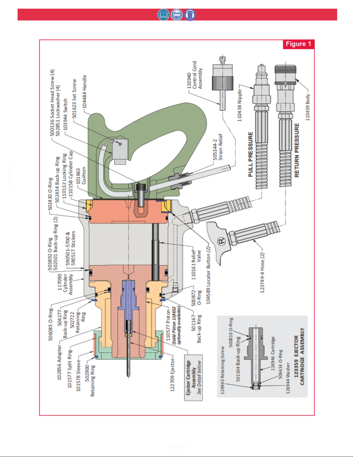
For component identification, refer to Figure 1.
The following procedure is for disassembly of Tool.
3.
Remove one Locator Button and unscrew Locking
Ring using spanner wrench. Remove the second
Remove only those parts necessary. Check and
Locator Button.
replace damaged/worn components. Always replace
O-rings, wipers, and back-up rings of disassem-
4. Screw Locking Ring part way in. Screw two Socket
bled subassemblies.
Head Screws into Cylinder Cap. Use pry bars
under the heads of the screws to gradually pry
NOTE: Be sure POWERIG is turned “OFF” when
removing the nose assembly to clean or replace
5.
Cylinder Cap out of Cylinder Assembly.
Remove Rnloading Valve.
components. See applicable Nose Assembly Data
Sheet for additional instructions.
6. Drain hydraulic fluid from Cylinder Assembly.
During disassembly and assembly, take the following
precautions to avoid damaging tool or components:
(a) Always work on a clean surface.
(b) Use relatively soft materials, such as brass, alu-
minum or wood, to protect tool when applying pressure.
(c) Apply a continuous strong pressure, rather than
sharp blows, to disassemble or assemble a component. An arbor press provides steady pressure to
press a component in or out.
(d) Never continue to force a component if it
“hangs.up” due to misalignment. Reverse the procedure to correct misalignment and start over.
(e) Smear Lubriplate 130AA
T.M
or equivalent, on O-
AANNDD
rings and mating surfaces to aid assembly and prevent damage to O-rings.
(Lubriplate is a registered trademark of Fiske Brothers
Refining Co. A handy tube of Lubriplate 130AA is available from Huck as part number 502723).
A special Spanner Wrench, Part No. 110362, is available from Huck to aid in the disassembly and assembly of Locking Ring, reference No. 11. Piston Rod
Guide Part No. 102862 are available to prevent damage to piston rod seals when assembling the piston.
Standard hand tools such as wrenches, drifts, copper
or lead hammers, screwdrivers, socket screw hexagon
keys, long forceps (tweezers), etc. Which can be purchased at most local supply firms are required. If possible, an arbor press and vise with soft jaws should be
available.
WARNING: Be sure to disconnect Tool’s
electrical control trigger system from
POWERIG® Hydraulic Unit BEFORE disconnecting Tool’s hydraulic hoses from
unit. If not disconnected in this order
before any maintenance or cleaning is
1. Remove Retaining Ring from Split Ring, slide off
done, severe personal injury may occur.
Sleeve and remove Split Ring segments. Pull nose
assembly anvil off and unscrew nose collet assembly.
2. Remove four Socket Head Screws and
Lockwashers from Handle. Handle Assembly and
Cushion are now separated from the Tool.
7. Unscrew Hoses.
8. Press Piston out of CylinderAssembly. Use an
arbor press if one is available.
9. Unscrew Ejector Cartridge Assembly using 7/16
socket wrench. Slide Ejector out of cartridge
assembly. Unscrew Retaining Screw from cartridge
assembly using 3/16 allen wrench.
10. Remove Retaining Ring.
11. Press Adapter out of Cylinder Assembly.
12. Use a small dull-pointed rod to remove O-Rings
and Back-up Rings from all components.
Page 12
507
HYDRAULIC INSTALLATION TOOL
(HK480)
Arconic
12
A
A
SSSSEEMMBBLLY
Y
I
I
NNSSTTRRUUCCTTIIOONNS
S
For component identification, refer to Figure 1.
Before assembling tool:
(a) Clean components In mineral spirits or other
solvent compatible With O-ring seals.
(b) Clean out O-Ring grooves.
(c) Inspect components for scoring, excessive wear or
damage.
(d) Replace O-Rings and back-up rings. Be sure that
relative positions of the O-Rings and back-up rings
are as shown in Figures.
(e) Specifications for O-Rings, back-up rings and
other standard components are shown in Table 5
so that they may be purchased locally.
(f) Smear Lubriplate 130AA on O-Rings and mating
surfaces to prevent damage to O-Rings and to aid
assembly.
WARNING: Do not omit any seals during
servicing, leaks will result and personal
injury may occur.
1. Press nose assembly adapter into Cylinder.
2. Place O-Ring and Washer into Ejector Cartridge.
Install Retaining Screw using 3/16 allen wrench.
Push pintail Ejector into Ejector Cartridge. Install
O-Ring and Back-up Ring on outside of Cartridge.
Screw Cartridge Assembly into Piston. Tighten
with 7/16 socket wrench. Note: Step 4 may be
done before assembling pintail Ejector and Ejector
Cartridge to Piston.
3. Place Piston Rod Guide P/N 102862 over the
threads of Piston rod and press Piston into
Cylinder and Adapter.
4. Place Relief Valve in hole in Piston.
5. Press Cylinder Cap into Cylinder so that the loca-
tor scallop in the cap matches the scallop in the
cylinder.
6. Place one Locator in matching scallops. (Cap can
be turned by putting a screw into one of the
tapped holes to use as a handle).
7. Screw Locking Ring into Cylinder using spanner
wrench.
8. Unscrew Locking Ring 1/4 turn or less until scallop
in Locking Ring matches scallop in Cylinder Cap.
Place Locator in matching scallops.
9. Position Cushion and Handle assembly in place
and assemble four Socket Head Screws and
Lockwashers. Tighten Screws to 490 inch pounds
torque if screws are plated and 655 inch pounds if
screws are unplated.
10. Screw Hoses into Cylinder. Coat hose fitting
threads with a non-hardening TEFLONTM.
CAUTION: Do not use TEFLON® tape on pipe
threads. Pipe threads may cause tape to
shred resulting in tool malfunction. (Slic-
TM
Tite
number 503237.)
11. Screw coupler Nipple onto Hose assembled into
cylinder PORT “P.”
12. Screw coupler Body onto Hose assembled into
cylinder PORT “R.” (Note: Tool will malfunction if
coupler Nipple and Body are not properly assembled.)
13. Attach tool hoses to Powerig hoses and
actuate tool a few times to check operation
of tool and inspect for leaks caused by damaged O-Rings.
14. Assemble Split Ring, Sleeve and Retaining Ring
when attaching the nose assembly.
Handle Assembly
1. Screw body of cord grip part of Strain Relief into
Handle.
2. Slide Strain Relief cap over cord.
3. Slide Strain Relief grommet over cord.
4. Place Cord in Handle so that leads come out the
Switch pocket.
5. Assemble leads to rear of Switch.
6. Push Switch into Handle and retain
with Set Screw.
7. Slide cover (not shown) over other end of Cord.
8. Assemble cap (two-prong plug) to Cord,
and slide cover over cap.
WARNING: Tool must be fully assembled
with all components included.
is available in stick form as Huck part
Page 13
507
HYDRAULIC INSTALLATION TOOL
(HK480)
Arconic
15
Page 14

507
HYDRAULIC INSTALLATION TOOL
(HK480)
Arconic
15
T
T
RROOUUBBLLEESSHHOOOOTTIINNG
G
Always check the simplest possible cause of a malfunction first. For example, a loose or disconnected trigger
line. Then proceed logically, eliminating each possible cause until the defective part is located. Where possible,
substitute known good parts for suspected defective parts. Use Trouble Shooting Chart as an aid for locating
and correcting trouble.
1. Tool fails to operate when trigger is depressed.
a. Inoperative POWERIG® Hydraulic Unit. Check
power source and/or see applicable Powerig
instruction manual.
b. Loose or disconnected control cord.
c. Damaged trigger assembly.
d. Loose or faulty hydraulic hose couplings.
2. Tool leaks hydraulic fluid.
a. Defective Tool O-rings or loose hose connections
at Tool.
3. Hydraulic couplers leak fluid.
a. Damaged or worn O-rings in coupler body.
4. Hydraulic fluid overheats.
a. Powerig not operating properIy.
b. Hydraulic couplers not completely tightened.
d. Restriction in hydraulic line.
10. Pull grooves on fastener pintail stripped during
PULL stroke.
a. Broken pintail not removed from tool.
b. Anvil was not slid completely onto fastener pintail.
c. Incorrect fastener length.
d. Worn or damaged jaw segments.
e. Metal particles accumulated in pull grooves of
jaw segments.
f. Excessive sheet gap.
11. Tool operates in reverse.
a. Reversed hydraulic hose connections between
POWERIG and tool.
12. Anvil will not slide completely over fastener pintail.
a. Broken pintail not removed from tool.
b. Incorrect fastener length.
5. Tool operates erratically and fails to install fastener
properly.
a. Low or erratic hydraulic pressure; air in system
b. Damaged or worn piston/anvil O-ring in Tool.
c. Excessive wear on sliding surfaces of Tool parts.
d. Relief Valve too short, worn, or peened over.
6. Collar of HUCKBOLT® fastener not completely
swaged.
a. Improper Tool operation. See Trouble 5.
b. Scored anvil.
7. Tool “hangs-up” on swaged collar of HUCKBOLT
Fastener.
a. Improper Tool operation. See Trouble 5.
b. RETURN pressure too low.
8. Pintail of fastener fails to break.
a. Improper Tool operation. See Trouble 5.
b. Pull grooves on fastener stripped. See Trouble 10.
c. PULL pressure too low.
9. Jaw segments do not maintain proper position in
piston.
a. Incorrect amount of follower O-rings. Clean before
reassembling.
Page 15

507
HYDRAULIC INSTALLATION TOOL
(HK480)
Arconic
15
LIMITED WARRANTIES
Limited Lifetime Warranty on BobTail® Tools:
Huck International, Inc. warrants to the original purchaser
that its BobTail® installation tools manufactured after
12/1/2016 shall be free from defects in materials and
workmanship for its useful lifetime. This warranty does
not cover special order / non-standard products, or part
failure due to normal wear, tool abuse or misapplication,
or user non-compliance with the service requirements and
conditions detailed in the product literature.
Two Year Limited Warranty on Installation Tools:
Huck International, Inc. warrants that its installation tools
manufactured after 12/1/2016 shall be free from defects in
materials and workmanship for a period of two years from
date of purchase by the end user. This warranty does not
cover special order / non-standard products, or part failure
due to normal wear, tool abuse or misapplication, or user
non-compliance with the service requirements and
conditions detailed in the product literature.
90 Day Limited Warranty on Nose Assemblies and
Accessories:
Huck International, Inc. warrants that its nose assemblies
and accessories shall be free from defects in materials and
workmanship for a period of 90 days from date of
purchase by the end user. This warranty does not cover
special clearance noses, or special order / non-standard
product, or part failure due to normal wear, abuse or
misapplication, or user non-compliance with the service
requirements and conditions detailed in the product
literature.
Useful lifetime is defined as the period over which the product
is expected to last physically, up to the point when replacement
is required due to either normal in-service wear, or as part of a
complete overhaul. Determination is made on a case-by case
basis upon return of parts to Huck International, Inc. for
evaluation.
Tooling, Part(s) and Other Items not manufactured by
Huck:
HUCK makes no warranty with respect to the tooling,
part(s), or other items manufactured by third parties.
HUCK expressly disclaims any warranty expressed or
implied, as to the condition, design, operation,
merchantability, or fitness for use of any tool, part(s), or
other items thereof not manufactured by HUCK. HUCK
shall not be liable for any loss or damage, directly or
indirectly, arising from the use of such tooling, part(s), or
other items or breach of warranty or for any claim for
incidental or consequential damages.
Huck shall not be liable for any loss or damage resulting
from delays or non-fulfillment of orders owing to strikes,
fires, accidents, transportation companies or for any
reason or reasons beyond the control of the Huck or its
suppliers.
Huck Installation Equipment:
Huck International, Inc. reserves the right to make changes
in specifications and design and to discontinue models
without notice.
Huck Installation Equipment should be serviced by trained
service technicians only.
Always give the serial number of the equipment when
corresponding or ordering service parts.
Complete repair facilities are maintained by Huck
International, Inc. Please contact one of the offices listed
below.
Eastern
One Corporate Drive Kingston, New York 12401-0250
Telephone (845) 331-7300 FAX (845) 334-7333
Outside USA and Canada
Contact your nearest Huck International location (see
reverse).
In addition to the above repair facilities, there are
Authorized Tool Service Centers (ATSC’s) located
throughout the United States. These service centers offer
repair services, spare parts, Service Parts Kits, Service Tool
Kits and Nose Assemblies. Please contact your Huck
Representative or the nearest Huck International location
(see reverse) for the ATSC in your area.
Page 16
For the Long Haul
™
 Loading...