

Page 1
\\Fileserver\text\PLAY\Play Installation Instructions\Installation Instructions 2012-2013\4585-MD4-01-en-000.doc - 1 -
A Assembly Instructions
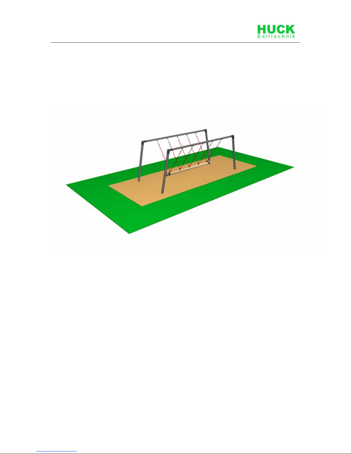
Cyclops Rope-End Swinger
(Mini, 4 Seater, Single)
Art. 4585-MD4
Operator: _____________________________________________________
Location: _____________________________________________________
Page 2

2 \\Fileserver\text\PLAY\Play Installation Instructions\Installation Instructions 2012-2013\4585-MD4-01-en-000.doc
Revision history
Revision 0 – 2010-09-02
The first allowed version
Assembly instructions JF
All rights reserved
© Copyright 2010 Huck Seiltechnik GmbH
Page 3

\\Fileserver\text\PLAY\Play Installation Instructions\Installation Instructions 2012-2013\4585-MD4-01-en-000.doc - 3 -
Contents
A Assembly Instructions ...................................................................................................................1
2 Datasheet.........................................................................................................................................6
3 Delivery contents (parts list with part numbers).........................................................................8
4 Erection instructions................................................................................................................... 11
5 Post installation checks.............................................................................................................. 19
B Maintenance instructions ........................................................................................................... 17
6 Introduction Maintenance........................................................................................................... 19
7 General maintenance information.............................................................................................. 20
8 Maintenance timetable ................................................................................................................ 22
9 Regular maintenance .................................................................................................................. 23
10 Monthly maintenance.................................................................................................................. 24
11 Quarterly maintenance................................................................................................................ 24
12 Half yearly maintenance.............................................................................................................. 24
13 Annual maintenance.................................................................................................................... 25
14 Maintenance printout................................................................................................................... 26
15 Hand over document................................................................................................................... 28
List of Tables
Table 3-1: Delivery contents, in words.....................................................................................................8
Table 3-2: Delivery contents, in symbols..................................................................................................9
Page 4
4 \\Fileserver\text\PLAY\Play Installation Instructions\Installation Instructions 2012-2013\4585-MD4-01-en-000.doc
1 Introduction Assembling
1.1 General information
This equipment should be installed, inspected, maintained and operated in
accordance with EN1176-7 guidelines.
Before installation work commences, please check that you have all of
the equipment and fixation components in the parts list provided (see
Tables 3-1 and 3-2).
Please consider that the installation has to be carried out only on even
terrain (max.slope up to 3%).
Any spare parts that may be required can be obtained directly from your
supplier.
Please do not hesitate to call your supplier if you have any problems during
installation or in case of any other questions.
Following installation, complete assembly instructions, maintenance
instructions and a maintenance record must be sent to the operator who
must confirm receipt in writing. See the last page of this document.
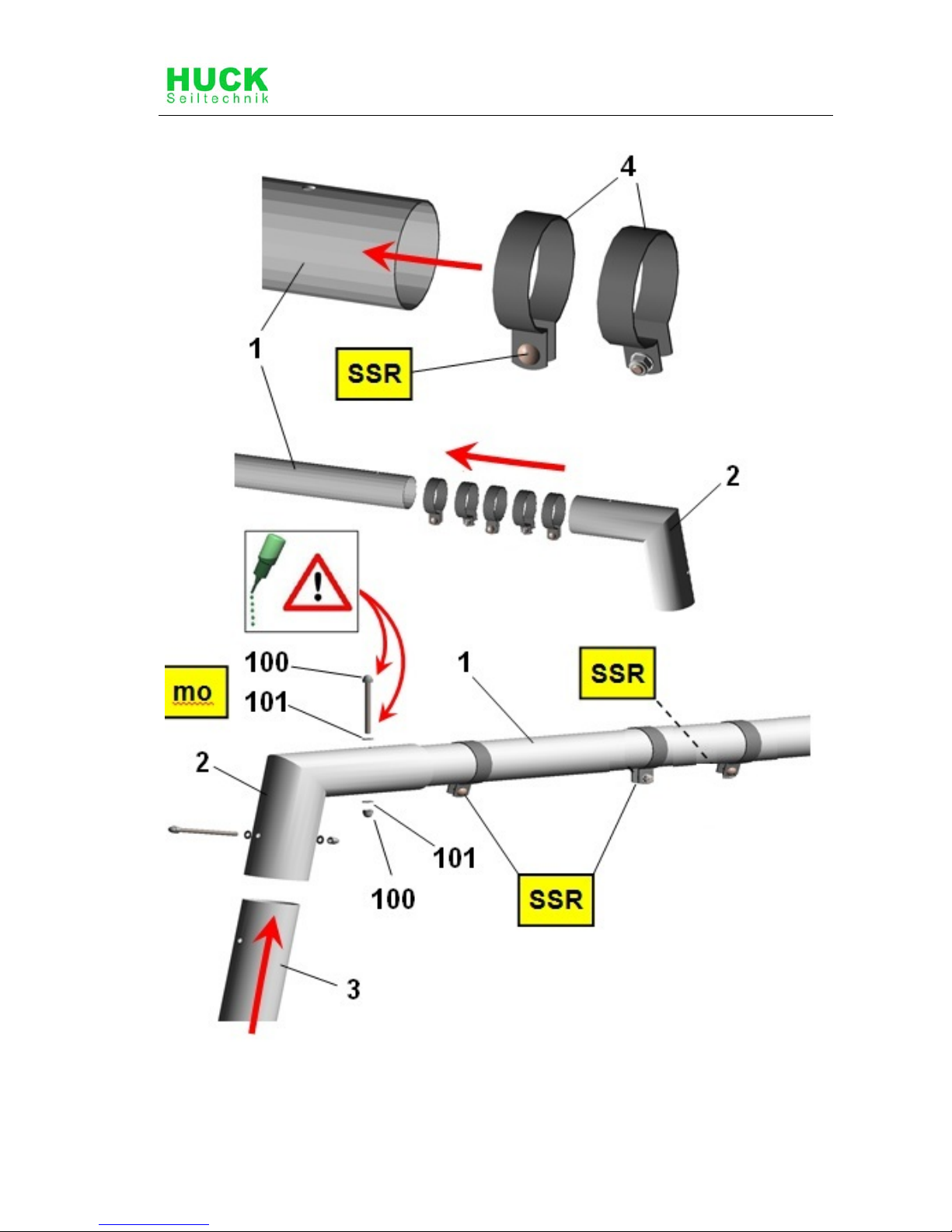
All nuts and bolts are hot-dip galvanised or stainless steel.
One of the characteristics of stainless steel is that uncontrolled cold
welding may occur when the nuts are tightened. To prevent this, it is
necessary to spray the nuts and bolts with Teflon spray or another similar
lubricant.
We hereby confirm that this play equipment has been tested and
certified in accordance with the play equipment standard EN 1176.
Page 5

\\Fileserver\text\PLAY\Play Installation Instructions\Installation Instructions 2012-2013\4585-MD4-01-en-000.doc - 5 -
Drawings / Views
All optical drawings are showing only the measurements/dimensions and
are no mandatory technical views of the complete item.
We reserve the right to change technical details of our articles which are
serving for the further development of our articles and are reasonable for
the customer.
Measurement tolerances
Because of the properties and characteristics of the components, minor
measurement tolerances compared to the indication on the sketches are
possible.
This concerns all shown measurements except the foundation
measurements resp. measurements below upper edge ground level/play
area.
Page 6
6 \\Fileserver\text\PLAY\Play Installation Instructions\Installation Instructions 2012-2013\4585-MD4-01-en-000.doc
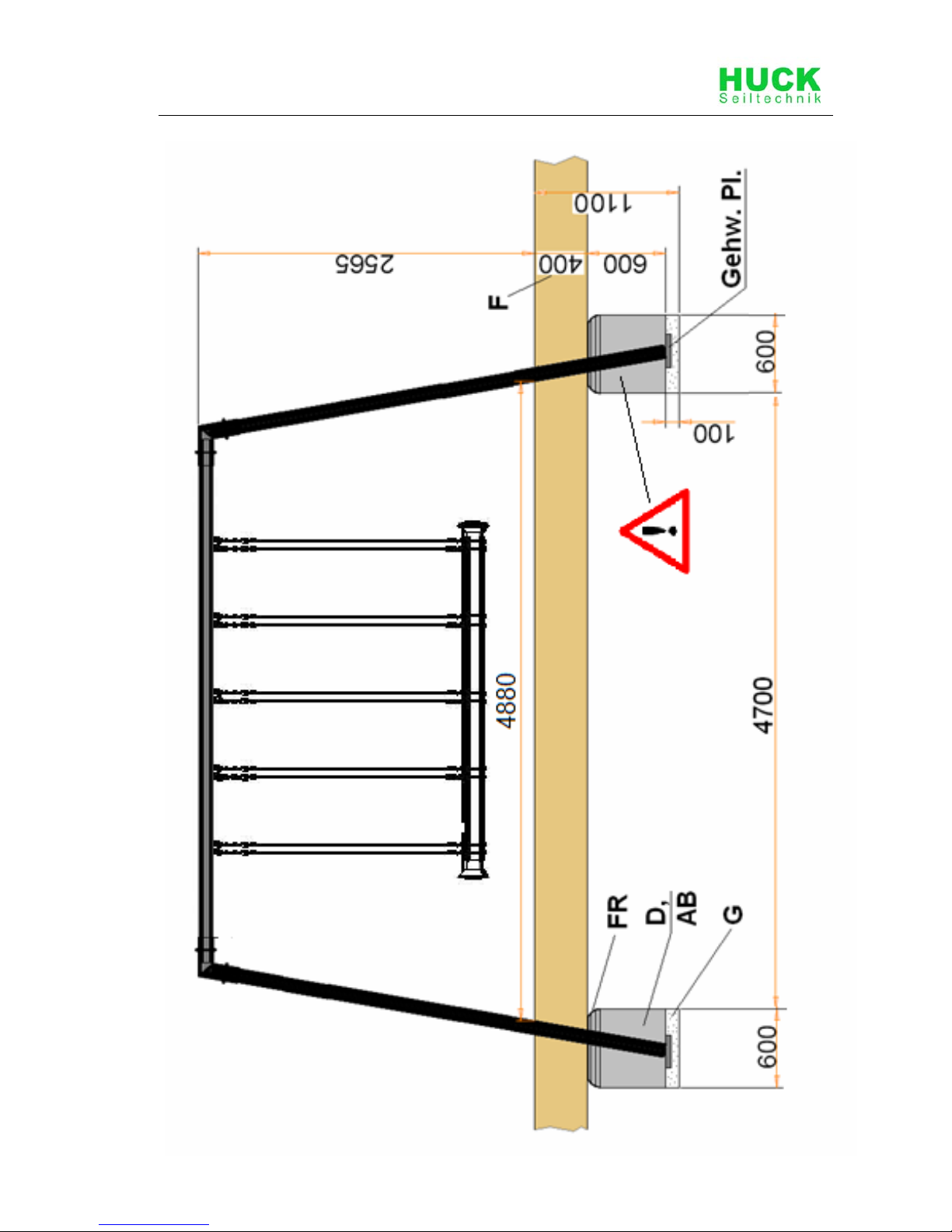
2 Datasheet: Cyclops Rope-End Swinger
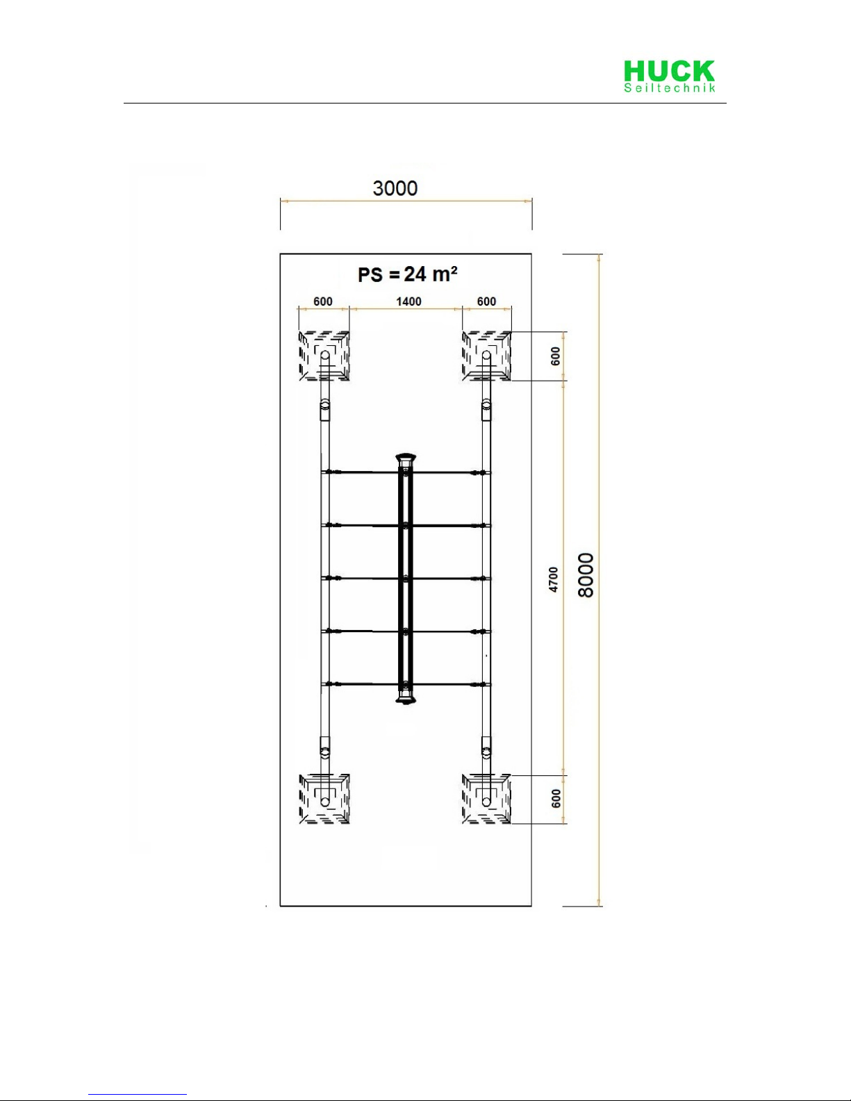
1. Space requirement: 8.0m x 3,0m including safety zone, height of fall 1.50m
The Images (individual drawings) are not to scale !!
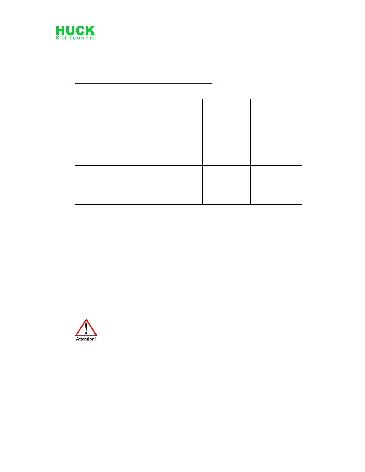
2. Required safety surface:
Surface material Description
mm
Minimum
thickness of
layer
mm
Maximum
height of fall
mm
Topsoil grass <= 1000*
Chipped bark 20 – 80 grain size 300/400 <= 2000/3000
Wood chippings 5 – 30 grain size 300/400 <= 2000/3000
Sand 0.2 – 2 grain size 300/400 <= 2000/3000
Gravel 2 – 8 grain size 300/400 <= 2000/3000
Other ground
materials
As recommended by
manufacturer
3. Name and overall dimension of the largest component:
Steel post (1 piece) length 4,0m, ø 102 mm
4. Name and weight of the heaviest component:
Steel post ( piece), approx. 26 kg
5. Intended age group: 4 years and over
6. Please note that this equipment is set in concrete.
Concrete: C25/30
Required concrete: 0.86 m
3
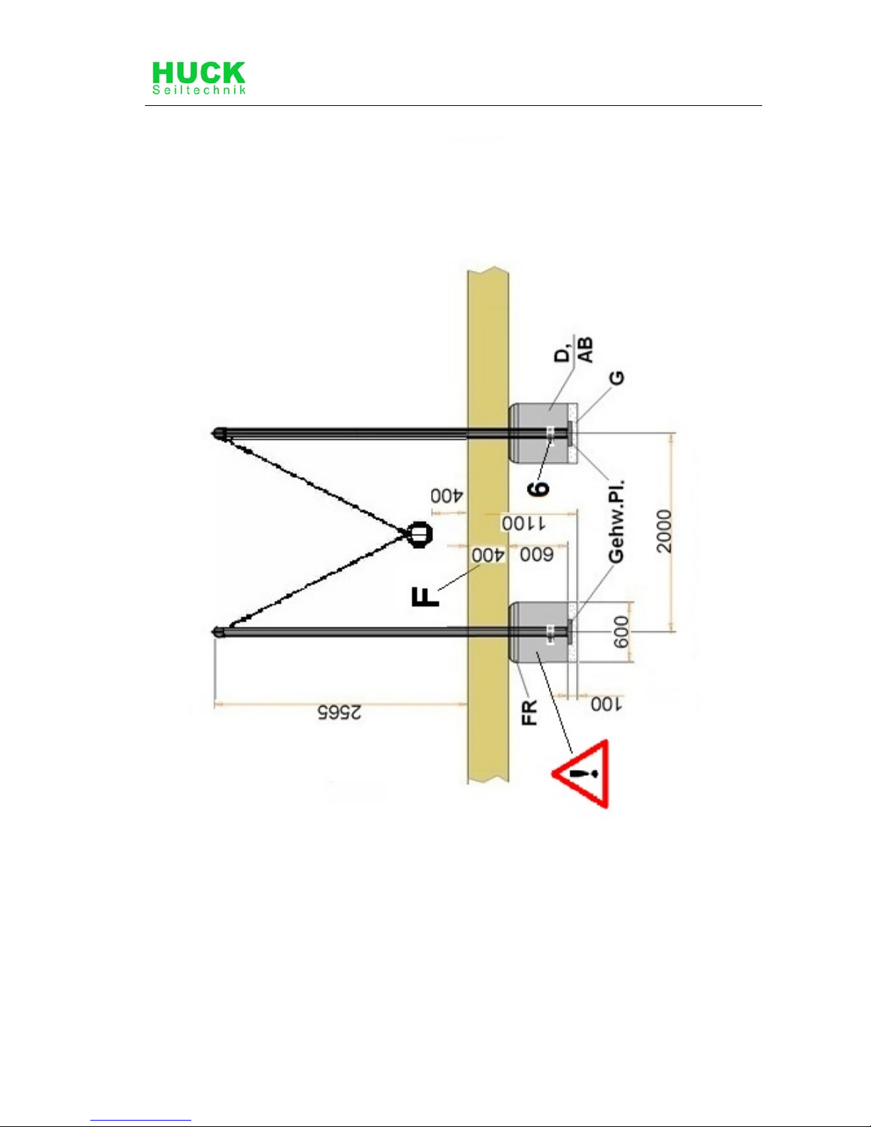
Foundations/area to be excavated:
6 x 0.60 m long x 0.60 m wide, total depth 1.10 m including .10 cm drainage
and .40cm Surface material.
Round off foundation edges (min.R = 100 mm)! Sizes of fundations are “4-5”
(natural ground).
Soil class 4: soft to medium plasticity, interleave bound, with minor portion of
stone (portion < 30% with bigger diameter of 63 mm grain size).
Soil class 5 : ground with soil class 3 and 4 with big portion of stones
(portion > 30% with bigger diameter of 63 mm grain size).
In case of sandy and soft soils, the surface measure of foundations have to be
enlarged for about 50%!
Page 7

\\Fileserver\text\PLAY\Play Installation Instructions\Installation Instructions 2012-2013\4585-MD4-01-en-000.doc - 7 -
7. Assembly time, once foundations completed: 4 hours.
Required assistants: 2-3 persons.
8. Any spare parts which may be required can be obtained directly from
your supplier.
9. We hereby confirm that this item of play equipment has been tested and
certified in accordance with the play equipment standard EN 1176.
Page 8
8 \\Fileserver\text\PLAY\Play Installation Instructions\Installation Instructions 2012-2013\4585-MD4-01-en-000.doc
3 Delivery contents (parts list with part numbers)
3.1 In words
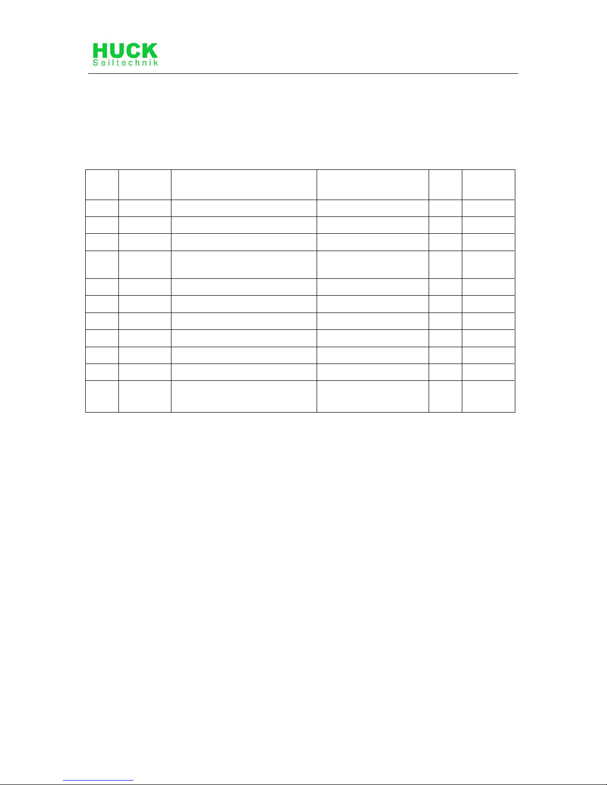
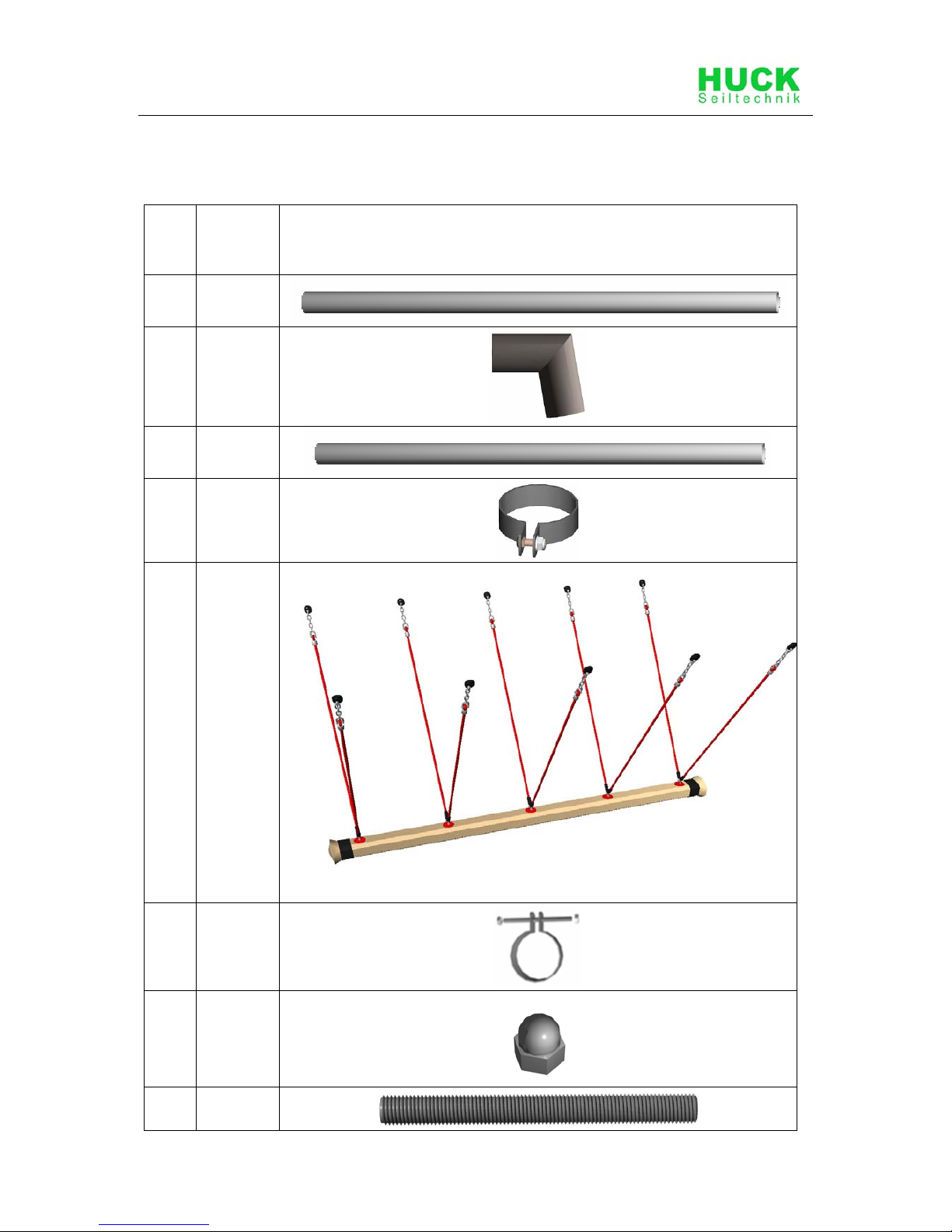
Table 3-1: Delivery contents, in words
Pos. Quantity Element /
Description
Size O.K. Missing
1
2
Steel Pipe Ø 102 mmx 4,00 m
2
4
Corner Pipe Connectors Ø 114 mm
3
4
Steel Pipe Ø 102 mmx 3,50 m
4
10
Tube Clamps with Carriage
Bolts
For Ø 102 mm
5
1
Rope End Swingers
6
4
Anker Clamps For Ø 102 mm
100
16
Acorn Nuts M10
101
8
Threaded Rod M10 x 130
102
16
Washers For M10
103
2
Loctite
2
Sidewalk fllagstone
/provided by the customer!
Page 9
\\Fileserver\text\PLAY\Play Installation Instructions\Installation Instructions 2012-2013\4585-MD4-01-en-000.doc - 9 -
3.2 In symbols
Table 3-2: Delivery contents, in symbols
Pos. Quantity Symbol
1
2
2
4
3
4
4
10
5
1
6
4
7
16
8
8
Page 10
10 \\Fileserver\text\PLAY\Play Installation Instructions\Installation Instructions 2012-2013\4585-MD4-01-en-000.doc
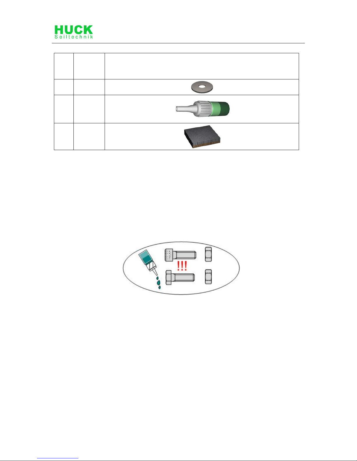
Pos. Quantity Symbol
9
16
10
2
11
4
Loctite-Thread locking Adhesive
!
Glue all screws, nuts and sleeves with loctite.
(not less than 5 drops !)
(except for lock nuts)
Page 11
\\Fileserver\text\PLAY\Play Installation Instructions\Installation Instructions 2012-2013\4585-MD4-01-en-000.doc - 11 -
4 Erection Instructions
Page 12
12 \\Fileserver\text\PLAY\Play Installation Instructions\Installation Instructions 2012-2013\4585-MD4-01-en-000.doc
Page 13
\\Fileserver\text\PLAY\Play Installation Instructions\Installation Instructions 2012-2013\4585-MD4-01-en-000.doc - 13 -
Page 14
14 \\Fileserver\text\PLAY\Play Installation Instructions\Installation Instructions 2012-2013\4585-MD4-01-en-000.doc
Page 15
\\Fileserver\text\PLAY\Play Installation Instructions\Installation Instructions 2012-2013\4585-MD4-01-en-000.doc - 15 -
Page 16
16 \\Fileserver\text\PLAY\Play Installation Instructions\Installation Instructions 2012-2013\4585-MD4-01-en-000.doc
Page 17
\\Fileserver\text\PLAY\Play Installation Instructions\Installation Instructions 2012-2013\4585-MD4-01-en-000.doc - 17 -
Page 18
18 \\Fileserver\text\PLAY\Play Installation Instructions\Installation Instructions 2012-2013\4585-MD4-01-en-000.doc
Abreviations
A
View
AB
Setting time at least 7-8 days
D
Concrete C25/30 (for foundations)
Dt.
Detail view
FR
Foundation round-off radius at least 10 cm
G
Drainage
R
Radius
mo
Connect
VO
Pre-fitted
Gehw.Pl.
Sidewalk flagstone (by the customer)!
Upper edge – drainaget (see drawing)
F
Fall protection
O.K
Upper edge of playing level
PS
Safety area
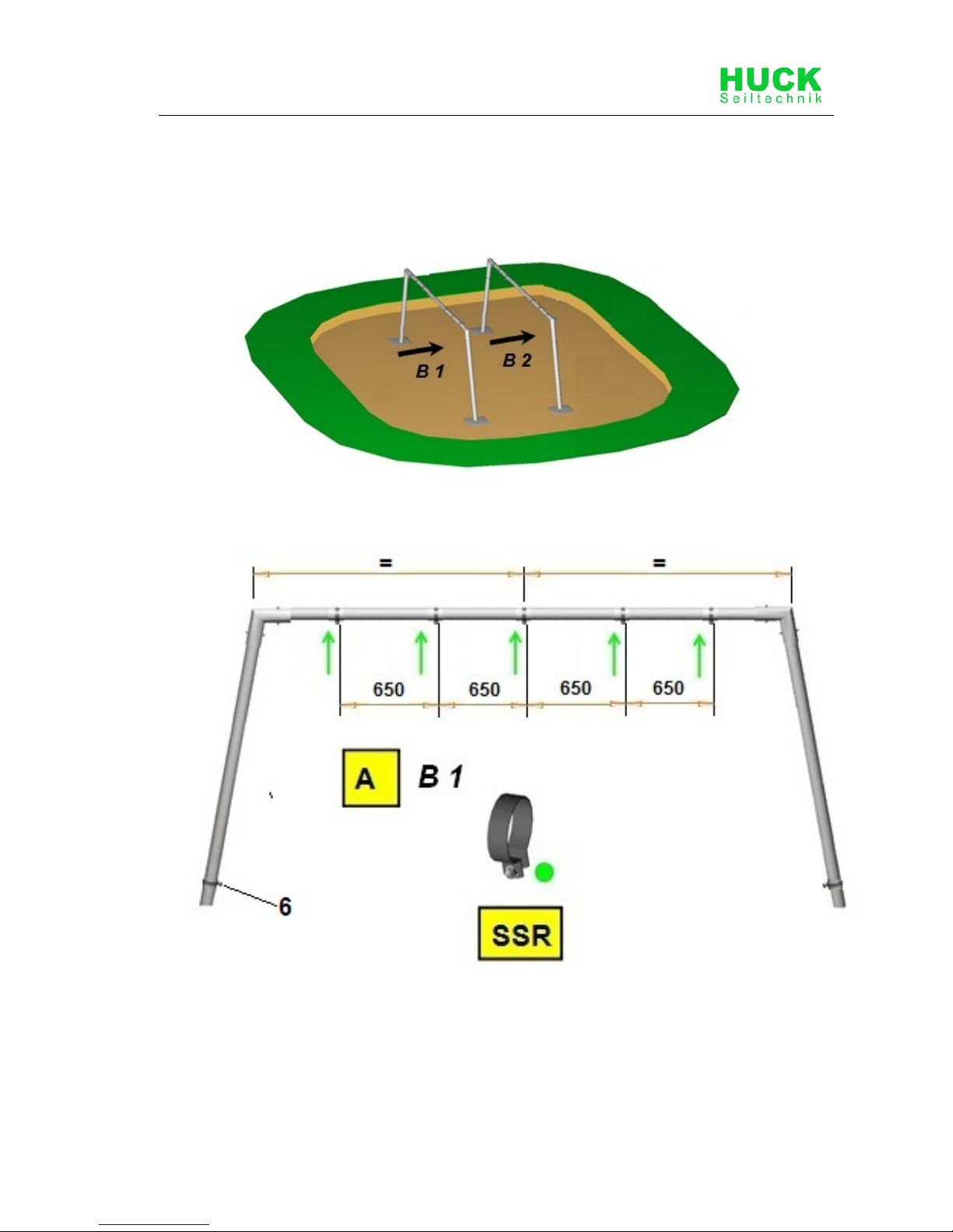
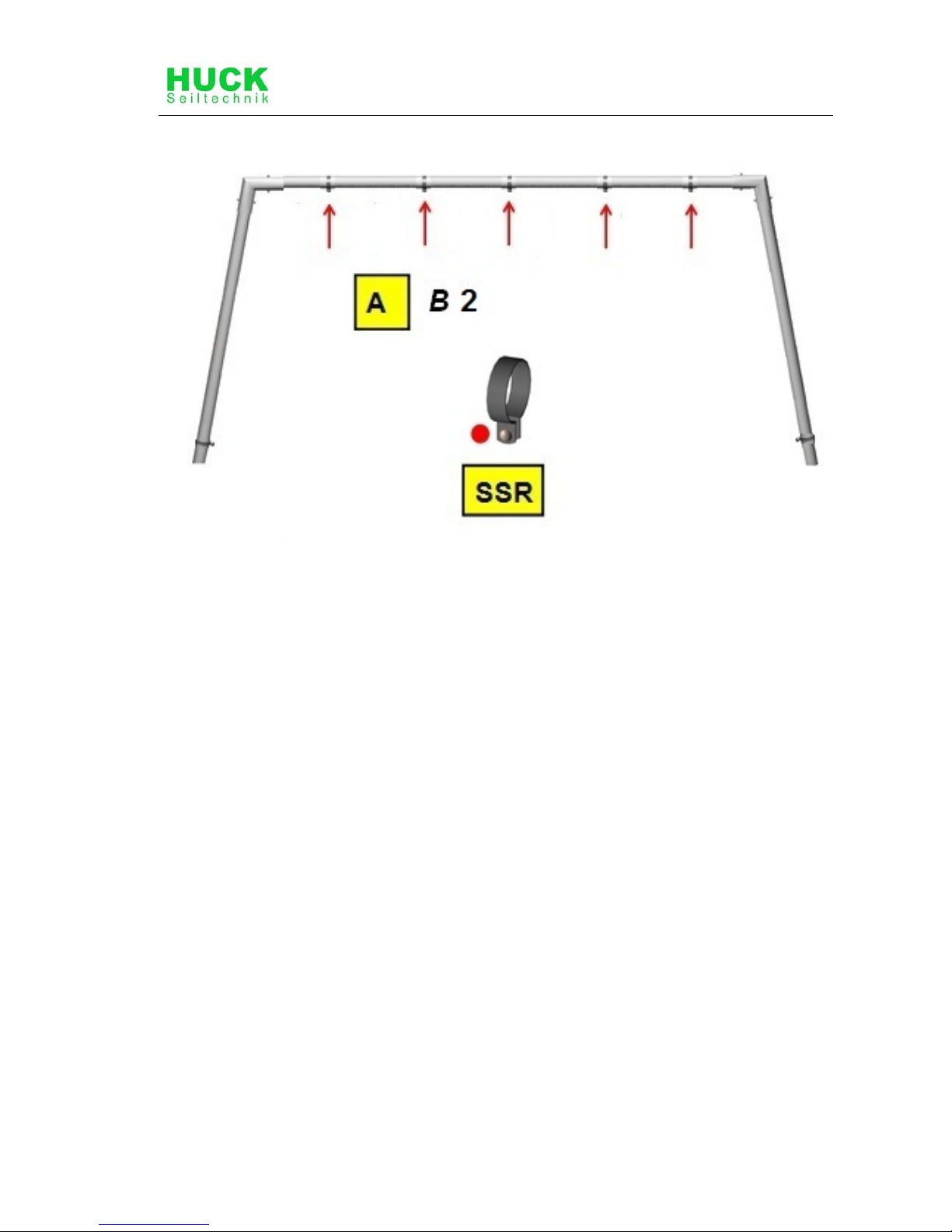
SSR
Install nuts on the bottom side
Round off foundation edges (min.R = 100 mm)! Sizes of
fundations are designed for soils class “4-5” (natural
ground).
Soil class 4: soft to medium plasticity, interleave bound,
with minor portion of stone (portion < 30% with bigger
diameter of 63 mm grain size).
Soil class 5 : ground with soil class 3 and 4 with big
portion of stones (portion > 30% with bigger diameter of
63 mm grain size).
In case of sandy and soft soils, the surface measure of
foundations have to be enlarged for about 50%!
See drawings for details of shortcuts
Page 19

\\Fileserver\text\PLAY\Play Installation Instructions\Installation Instructions 2012-2013\4585-MD4-01-en-000.doc - 19 -
5 Post installation checks
If the equipment has not been installed safely, you must ensure that the
public is prevented from using it.
5.1 Marking filler depth
• Labelling the posts to show the depth of material provided as fall protection
(i.e. loose filler).
5.2 The equipment has not been installed safely in the following cases:
• Installation of equipment is not complete.
• The protective surface has not been installed yet.
• Appropriate maintenance work cannot guarantee operational safety.
5.3 Removal of all assembly aids
• Please make sure that all assembly aids have been removed from the
playing area. The equipment must not be approved for use until this check
has been carried out.
5.4 Information about inspection of the equipment before it is used for the
first time
• There are no special inspection requirements to be met before the
equipment is used for the first time.
5.5 Retighten bolts
• After one week of play, please retighten all bolts again. Later upon
respective maintenance.
Page 20

Page 21
\\Fileserver\text\PLAY\Play Installation Instructions\Installation Instructions 2012-2013\4585-MD4-01-en-000.doc - 17 -
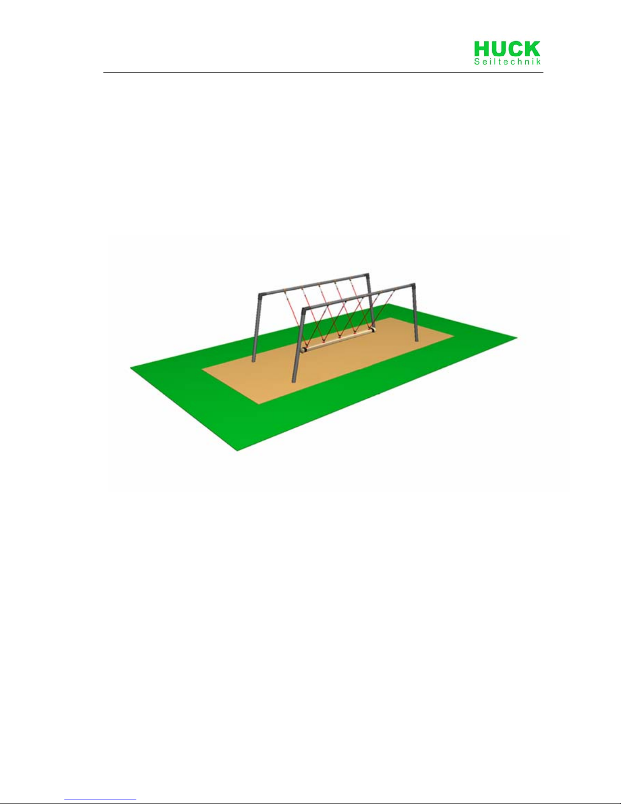
B Maintenance Instructions
Cyclops Rope-End Swinger
(Mini, 4 Seater, Single)
Art. 4585-MD4
Page 22

18 \\Fileserver\text\PLAY\Play Installation Instructions\Installation Instructions 2012-2013\4585-MD4-01-en-000.doc
Revision history
Revision 0 – 2010-09-02
The first allowed version
Maiantanance instructions
All rights reserved
© Copyright 2010 Huck Seiltechnik GmbH
Page 23
\\Fileserver\text\PLAY\Play Installation Instructions\Installation Instructions 2012-2013\4585-MD4-01-en-000.doc - 19 -
6 Introduction Maintenance
6.1 General informations
This equipment should be installed, inspected, maintained and operated in
accordance with EN 1176-7 guidelines.
Please note: Providing any necessary repairs are carried out, a piece of
play equipment that is inspected regularly cannot become so damaged
that it is dangerous.
Any spare parts which may be required can be obtained directly from your
supplier.
This equipment should only be assembled, maintained and repaired by
persons with the necessary expertise.
A copy of the inspection record should be given to the operator,
who must confirm receipt.
This maintenance instruction is based on the standard
“EN 1176-1:2008”.
Page 24

20 \\Fileserver\text\PLAY\Play Installation Instructions\Installation Instructions 2012-2013\4585-MD4-01-en-000.doc
7 General maintenance information
7.1 Maintenance intervals
Maintenance intervals are based on average use. Please note that more
frequent inspections and/or maintenance are required if the play equipment is
subject to intensive use.
7.2 Inspection frequency
The frequency of inspections must be based on actual use. Factors that affect
frequency include vandalism, location (e.g. coastal proximity), air pollution and
the age of the equipment.
7.3 Maintenance products and procedures
All nuts and bolts are hot-dip galvanised or stainless steel. One of the
characteristics of stainless steel is that uncontrolled cold welding may occur
when the nuts are tightened. To prevent this, it is necessary to spray the nuts
and bolts with Teflon spray or another similar lubricant.
7.4 Spare parts
All spare parts must conform to the manufacturer’s specifications.
7.5 Identifying spare parts
All spare parts are listed in the parts list. The parts list follows the installation
requirements.
7.6 Special instructions for the disposal of individual equipment
components
No special instructions are necessary.
7.7 Special measures during the break-in period
No later than 2 weeks after assembly, all screwed connections should be
checked and tightened if necessary.
7.8 Maintenance of protective surfaces
Surfaces providing fall protection must also be maintained regularly. It is
particularly important to maintain the correct level of loose surface material
and add more if necessary.
Page 25
\\Fileserver\text\PLAY\Play Installation Instructions\Installation Instructions 2012-2013\4585-MD4-01-en-000.doc - 21 -
7.9 Faults
Damages must be repaired as soon as they are detected. If serious
defects that affect the safetyness cannot be repaired straight away, the
playground item must be blocked with immediate effect.
7.10 Loose screws
Loose screws always cause quality problems and put safety at risk.
Therefore, loose screws should always be tightened and checks carried
out to ensure that there are no missing screws.
7.11 Preventing equipment use
Use of the equipment should be prevented in the event of incomplete
installation, disassembly, maintenance, repairs and faults.
7.12 Claims/liability for faults (steel poles)
Steel posts and footings are covered by our guarantee if refular maintenance
is carried out and recorded in writing.
Our general terms and conditions apply. Maintenance of steel poles first takes
place after 3 years. The steel posts must be excavated down to the
concrete foundations and checked for corrosion.
Zinc paint should be applied to any corroded areas and scratches.
Check ropes for abrasion, replace ropes where coating is damaged down the
Steel inlet.
Page 26
22 \\Fileserver\text\PLAY\Play Installation Instructions\Installation Instructions 2012-2013\4585-MD4-01-en-000.doc
8 Maintenance timetable
8.1 Special advices
8.1.1 Maintenance interval
We strongly advise you to carry out inspections and maintenance work within
the specified periods as use of the equipment, the weather and malicious
vandalism cause wear and tear that compromises the safety and function of
the equipment.
8.1.2 Maintenance intervals in the event of intensive use
Please note that more frequent inspections and/or maintenance are required if
the play equipment is subject to intensive use.
8.1.3 Faults that compromise safety
In the event of a fault that compromises safety, quick action must be
taken. This may involve repairing it immediately or shutting down and
dismantling the equipment.
8.1.4 Faults that compromise function
Faults that compromise function should also be repaired immediately.
Such faults lower the value of the equipment to the user and encourage
malicious vandalism, which may render the equipment less safe. Any
damage should also be repaired immediately.
Page 27
\\Fileserver\text\PLAY\Play Installation Instructions\Installation Instructions 2012-2013\4585-MD4-01-en-000.doc - 23 -
9 Regular maintenance
Page 28

24 \\Fileserver\text\PLAY\Play Installation Instructions\Installation Instructions 2012-2013\4585-MD4-01-en-000.doc
10 Monthly maintenance
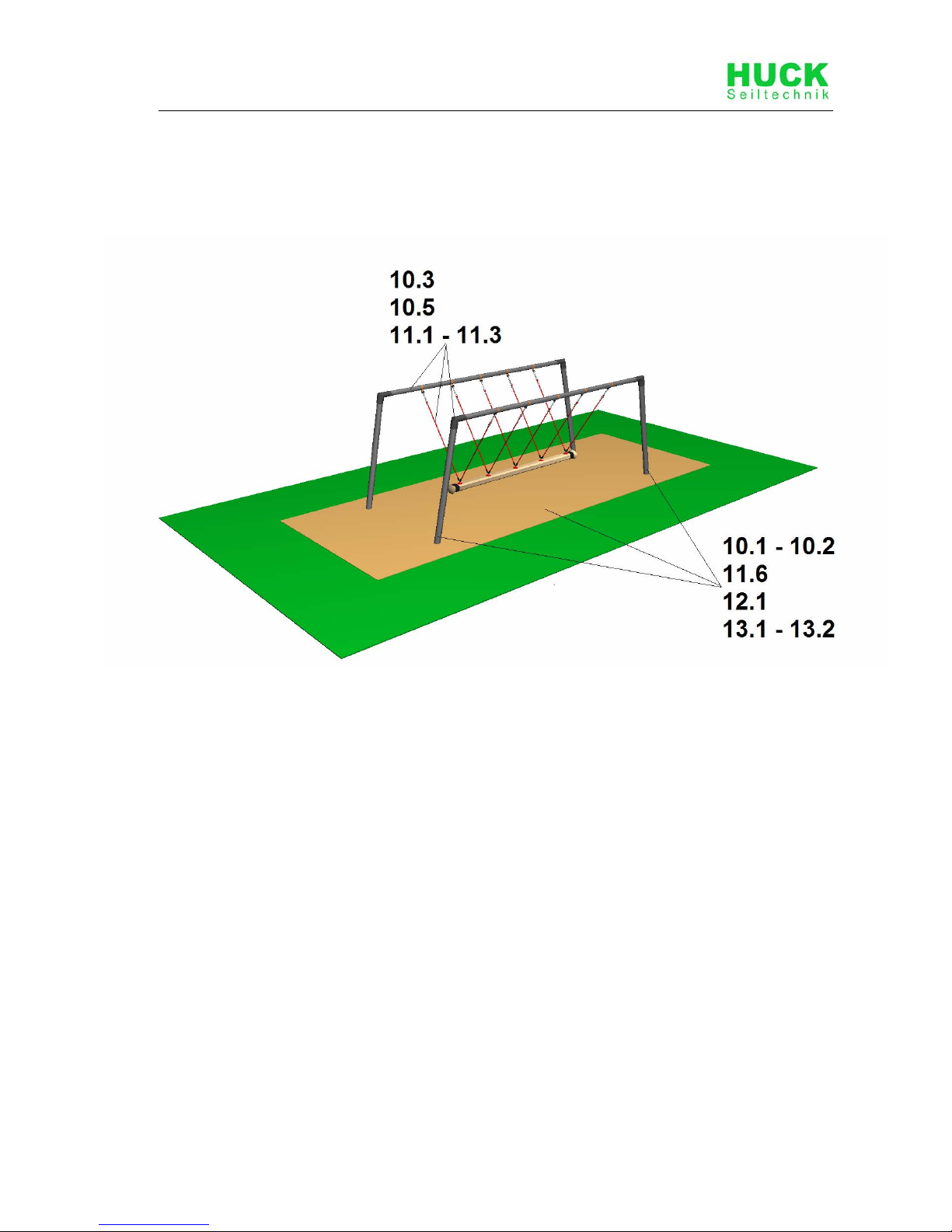
10.1 Check the spaces between the equipment and the ground (clearance and
height of fall).
10.2 Check the ground surface of fall protection for hard objects and loose
foundations.
10.3 Check all connecting elements and fittings for wear and tear and tighten
if necessary. Replace damaged or missing parts.
10.4 Check that moving metal parts (joints, springs, etc.) move smoothly and
are not worn. Replace if necessary. It is not necessary to lubricate joints
as we only use maintenance-free metal roller bearings.
10.5 Check all attachments such as chains, ropes, nets, etc. for damage and
replace if necessary.
10.6 Check rubber parts, sleeves, etc. for wear and tear or damage and
replace if necessary.
10.7 If necessary, remove excess padding material from the post footings due
to danger of rotting.
10.8 Check the surface of wooden parts for damage caused by the weather or
external influences and mould. Repair or replace if necessary.
10.9 Check the surface of plastic and metal parts, e.g. slides, for damage and
replace if necessary.
11 Quarterly maintenance
11.1 Detailed inspection of the operation and stability of the equipment
paying particular attention to any wear and tear.
11.2 Tighten all forms of attachment.
11.3 Repaint and retreat surfaces.
11.4 Maintenance of fall protection surfaces.
11.5 Lubrication of joints.
11.6 Check height of fall protection material and top up with loose filler if
necessary. If the posts are labelled, top up to the mark.
11.7 Retighten all bolts.
12 Half yearly maintenance
12.1 The stability of supporting posts, supports, foundations etc. has to be
checked. The safety level of the entire system has to be checked after
repairs have been carried out or additional system components have
been installed or replaced.
Page 29
\\Fileserver\text\PLAY\Play Installation Instructions\Installation Instructions 2012-2013\4585-MD4-01-en-000.doc - 25 -
Annual Maintenance
13 Annual maintenance
13.1 Ascertaining that the equipment, foundations and surfaces are safe for
operation.
13.2 In particular, the equipment should be checked for decay and corrosion.
It may be necessary to dig out or excavate certain components in order
to do so. Zinc paint should be applied to corroded areas and scratches.
.
The equipment must be inspected by someone with the necessary
expertise in strict compliance with the instructions issued by Huck
Seiltechnik GmbH.
A copy of the inspection record should be given to the operator,
who must confirm receipt.
Page 30
Huck Seiltechnik GmbH • 35614 Aßlar/Berghausen • Germany
[email protected] • www.huck.net
\\Fileserver\text\PLAY\Play Installation Instructions\Installation Instructions 2012-2013\4585-MD4-01-en-000.doc - 26 -
14 Maintenance printout
Name of item:Cyclops Swinger ____________________ / Art. No. 4585-MD4 __________________________________
Location: ________________________________________________________________________________________
Customer or operator: ______________________________________________________________________________
(Local Authority, Town Council, School, etc.)
Date of
inspection
Inspector O.K. Accessible Barriered Defects Repaired
by
Date
Please copy and return once a year after main inspection has been carried out to the manufacturer by Telefax
+49(0)6443/ 83 11 79!
Place the confirmation form in the play equipment files.
Page 31

Page 32
Huck Seiltechnik GmbH • 35614 Aßlar/Berghausen • Germany
[email protected] • www.huck.net
\\Fileserver\text\PLAY\Play Installation Instructions\Installation Instructions 2012-2013\4585-MD4-01-en-000.doc - 28 -
15 Hand over document
After the installation of the equipment pass the installation and
maintenance documents to the operator. The operator has to receive the
hand over documents. The complete filled and signed hand over
document should be sent to the supplier.
Art.-No.: 4585-MD4
Type of item: Cyclops Swinger
Serial number: _________________________________________________
Customer or operator (Local Authority, Town Council, School, etc.):
_____________________________________________________________
_____________________________________________________________
Competent person in charge:
_____________________________________________________________
_____________________________________________________________
Installation Company (address):
_____________________________________________________________
_____________________________________________________________
Responsible assistant (assembler):
_____________________________________________________________
_____________________________________________________________
Received the complete assembly instructions, maintenance instructions and
maintenance printout.
_____________________________________________________________
(Signature of operator) (Signature of Installation Company)
(Stamp)
Date: ___________________
 Loading...