

Page 1
07-10-2013
HK1109
INSTRUCTION MANUAL
256BT
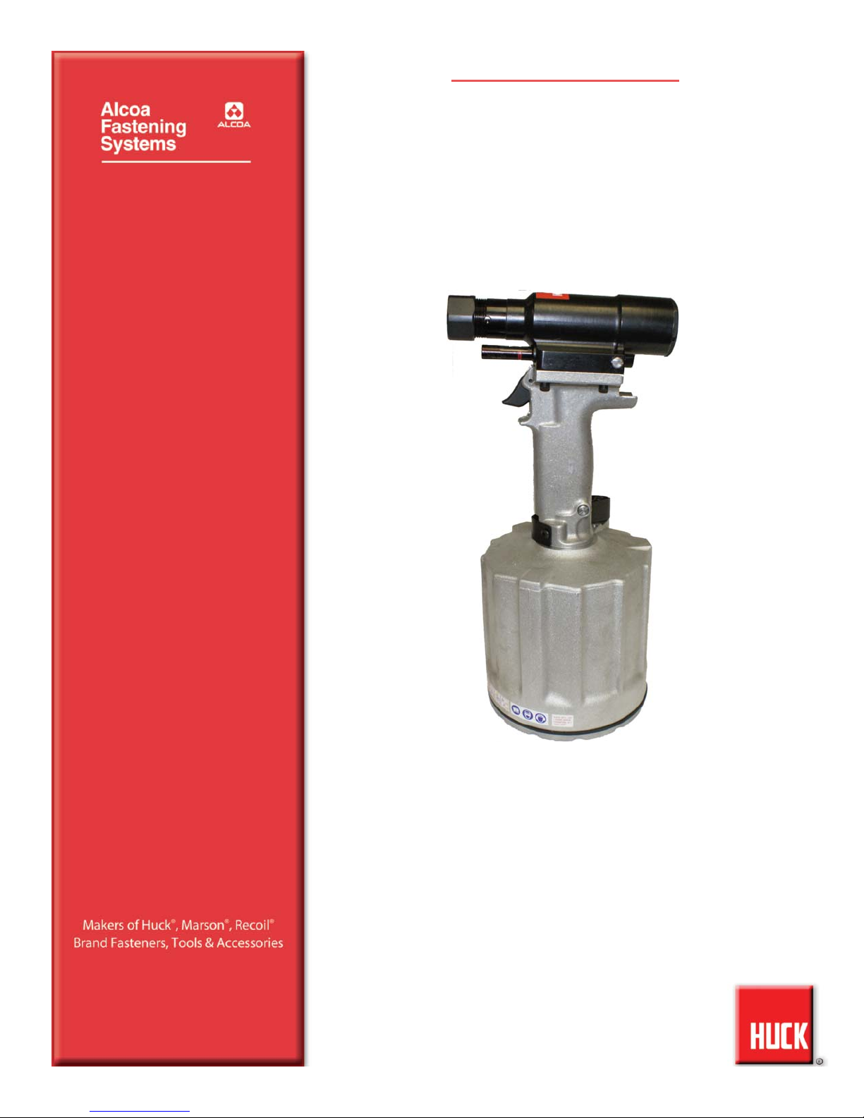
PNEUDRAULIC INSTALLATION TOOL
Page 2
256BT Pneudraulic Installation Tool (HK1109) Alcoa Fastening Systems
2
Page 3

256BT Pneudraulic Installation Tool (HK1109) Alcoa Fastening Systems
3
SAFETY
. . . . . . . . . . . . . . . . . . . . . . . . . . . . . . . . . . . . . . . . . . . . . . . . . . .4
SPECIFICATIONS
. . . . . . . . . . . . . . . . . . . . . . . . . . . . . . . . . . . . . . . . . . . . .5
PRINCIPLE OF OPERATION
. . . . . . . . . . . . . . . . . . . . . . . . . . . . . . . . . . . .6
OPERATING INSTRUCTIONS
. . . . . . . . . . . . . . . . . . . . . . . . . . . . . . . . . . . .6
MAINTENANCE
. . . . . . . . . . . . . . . . . . . . . . . . . . . . . . . . . . . . . . . . . . . . . .7
DISASSEMBLY
. . . . . . . . . . . . . . . . . . . . . . . . . . . . . . . . . . . . . . . . . . . . .8-9
ASSEMBLY
. . . . . . . . . . . . . . . . . . . . . . . . . . . . . . . . . . . . . . . . . . . . . .10-11
FILL AND BLEED
. . . . . . . . . . . . . . . . . . . . . . . . . . . . . . . . . . . . . . . .12-13
ASSEMBLY DRAWINGS
. . . . . . . . . . . . . . . . . . . . . . . . . . . . . . . . . . . .14-15
PARTS LIST
. . . . . . . . . . . . . . . . . . . . . . . . . . . . . . . . . . . . . . . . . . . .15-16
MEASURING TOOL STROKE
. . . . . . . . . . . . . . . . . . . . . . . . . . . . . . . . . .17
TROUBLESHOOTING
. . . . . . . . . . . . . . . . . . . . . . . . . . . . . . . . . . . . . . . . .18
ACCESSORIES
. . . . . . . . . . . . . . . . . . . . . . . . . . . . . . . . . . . . . . . . . . . . .18
C
C
ONTENTS
ONTENTS
Page 4
256BT Pneudraulic Installation Tool (HK1109) Alcoa Fastening Systems
4
I. GENERAL SAFETY RULES:
1. A half hour long hands-on training session with qualified personnel is
recommended before using Huck equipment.
2. Huck equipment must be maintained in a safe working condition at all
times. Tools and hoses should be inspected at the beginning of each
shift/day for damage or wear. Any repair should be done by a qualified
repairman trained on Huck procedures.
3. For multiple hazards, read and understand the safety instructions before
installing, operating, repairing, maintaining, changing accessories on, or
working near the assembly power tool. Failure to do so can result in
serious bodily injury.
4. Only qualified and trained operators should install, adjust or use the
assembly power tool.
5. Do not modify this assembly power tool. This can reduce effectiveness of
safety measures and increase operator risk.
6. Do not discard safety instructions; give them to the operator.
7. Do not use assembly power tool if it has been damaged.
8. Tools shall be inspected periodically to verify all ratings and markings
required, and listed in the manual, are legibly marked on the tool. The
employer/operator shall contact the manufacturer to obtain replacement
marking labels when necessary. Refer to assembly drawing and parts list
for replacement.
9. Tool is only to be used as stated in this manual. Any other use is
prohibited.
10. Read MSDS Specifications before servicing the tool. MSDS
specifications are available from the product manufacturer or your Huck
representative.
11.Only genuine Huck parts shall be used for replacements or spares. Use of
any other parts can result in tooling damage or personal injury.
12.Never remove any safety guards or pintail deflectors.
13.Never install a fastener in free air. Personal injury from fastener ejecting
may occur.
14.Where applicable, always clear spent pintail out of nose assembly before
installing the next fastener.
15.Check clearance between trigger and work piece to ensure there is no
pinch point when tool is activated. Remote triggers are available for
hydraulic tooling if pinch point is unavoidable.
16.Do not abuse tool by dropping or using it as a hammer. Never use
hydraulic or air lines as a handle or to bend or pry the tool. Reasonable
care of installation tools by operators is an important factor in maintaining
tool efficiency, eliminating downtime, and preventing an accident which
may cause severe personal injury.
17.Never place hands between nose assembly and work piece. Keep hands
clear from front of tool.
18.Tools with ejector rods should never be cycled with out nose assembly
installed.
19.When two piece lock bolts are being used always make sure the collar
orientation is correct. See fastener data sheet for correct positioning.
II. PROJECTILE HAZARDS:
1. Risk of whipping compressed air hose if tool is pneudraulic or pneumatic.
2. Disconnect the assembly power tool from energy source when changing
inserted tools or accessories.
3. Be aware that failure of the workpiece, accessories, or the inserted tool
itself can generate high velocity projectiles.
4. Always wear impact resistant eye protection during tool operation. The
grade of protection required should be assessed for each use.
5. The risk of others should also be assessed at this time.
6. Ensure that the workpiece is securely fixed.
7. Check that the means of protection from ejection of fastener or pintail is in
place and operative.
8. There is possibility of forcible ejection of pintails or spent mandrels from
front of tool.
III. OPERATING HAZARDS:
1. Use of tool can expose the operator’s hands to hazards including:
crushing, impacts, cuts, abrasions and heat. Wear suitable gloves to
protect hands.
2. Operators and maintenance personnel shall be physically able to handle
the bulk, weight and power of the tool.
3. Hold the tool correctly and be ready to counteract normal or sudden
movements with both hands available.
4. Maintain a balanced body position and secure footing.
5. Release trigger or stop start device in case of interruption of energy
supply.
6. Use only fluids and lubricants recommended by the manufacturer.
7. Avoid unsuitable postures, as it is likely for these not to allow
counteracting of normal or unexpected tool movement.
8. If the assembly power tool is fixed to a suspension device, make sure that
fixation is secure.
9. Beware of the risk of crushing or pinching if nose equipment is not fitted.
IV. REPETITIVE MOTION HAZARDS:
1. When using assembly power tool, the operator can experience discomfort
in the hands, arms, shoulders, neck or other parts of the body.
2. When using tool, the operator should adopt a comfortable posture while
maintaining a secure footing and avoid awkward or off balanced postures.
3. The operator should change posture during extended tasks to help avoid
discomfort and fatigue.
4. If the operator experiences symptoms such as persistent or recurring
discomfort, pain, throbbing, aching, tingling, numbness, burning
sensations or stiffness, these warnings should not be ignored. The
operator should tell the employer and consult a qualified health
professional.
V. ACCESSORIES HAZARDS:
1. Disconnect tool from energy supply before changing inserted tool or
accessory.
2. Use only sizes and types of accessories and consumables that are
recommended. Do not use other types or sizes of accessories or
consumables.
VI. WORKPLACE HAZARDS:
1. Be aware of slippery surfaces caused by use of the tool and of trip hazards
caused by the air line or hydraulic hose.
2. Proceed with caution while in unfamiliar surroundings; there could be
hidden hazards such as electricity or other utility lines.
3. The assembly power tool is not intended for use in potentially explosive
environments.
4. Tool is not insulated against contact with electrical power.
5. Ensure there are no electrical cables, gas pipes, etc., which can cause a
hazard if damaged by use of the tool.
VII. NOISE HAZARDS:
1. Exposure to high noise levels can cause permanent, disabling hearing
loss and other problems such as tinnitus, therefore risk assessment and
the implementation of proper controls is essential.
2. Appropriate controls to reduce the risk may include actions such as
damping materials to prevent workpiece from ‘ringing’.
3. Use hearing protection in accordance with employer’s instructions and as
required by occupational health and safety regulations.
4. Operate and maintain tool as recommended in the instruction handbook
to prevent an unnecessary increase in the noise level.
5. Select, maintain and replace the consumable / inserted tool as
recommended to prevent an unnecessary increase in noise.
6. If the power tool has a silencer, always ensure that it is in place and in
good working order when the tool is being operated.
VIII. VIBRATION HAZARDS:
1. Exposure to vibration can cause disabling damage to the nerves and
blood supply to the hands and arms.
2. Wear warm clothing when working in cold conditions and keep hands
warm and dry.
3. If numbness, tingling, pain or whitening of the skin in the fingers or hands,
stop using the tool, tell your employer and consult a physician.
4. Support the weight of the tool in a stand, tensioner or balancer in order to
have a lighter grip on the tool.
IX. PNEUMATIC / PNEUDRAULIC TOOL SAFETY INSTRUCTIONS:
1. Air under pressure can cause severe injury.
2. Always shut off air supply, drain hose of air pressure and disconnect tool
from air supply when not in use, before changing accessories or when
making repairs.
3. Never direct air at yourself or anyone else.
4. Whipping hoses can cause severe injury, always check for damaged or
loose hoses and fittings.
5. Cold air should be directed away from hands.
6. Whenever universal twist couplings (claw couplings) are used, lock pins
shall be installed and whipcheck safety cables shall be used to safeguard
against possible hose to hose or hose to tool connection failure.
7. Do not exceed maximum air pressure stated on tool.
8. Never carry an air tool by the hose.
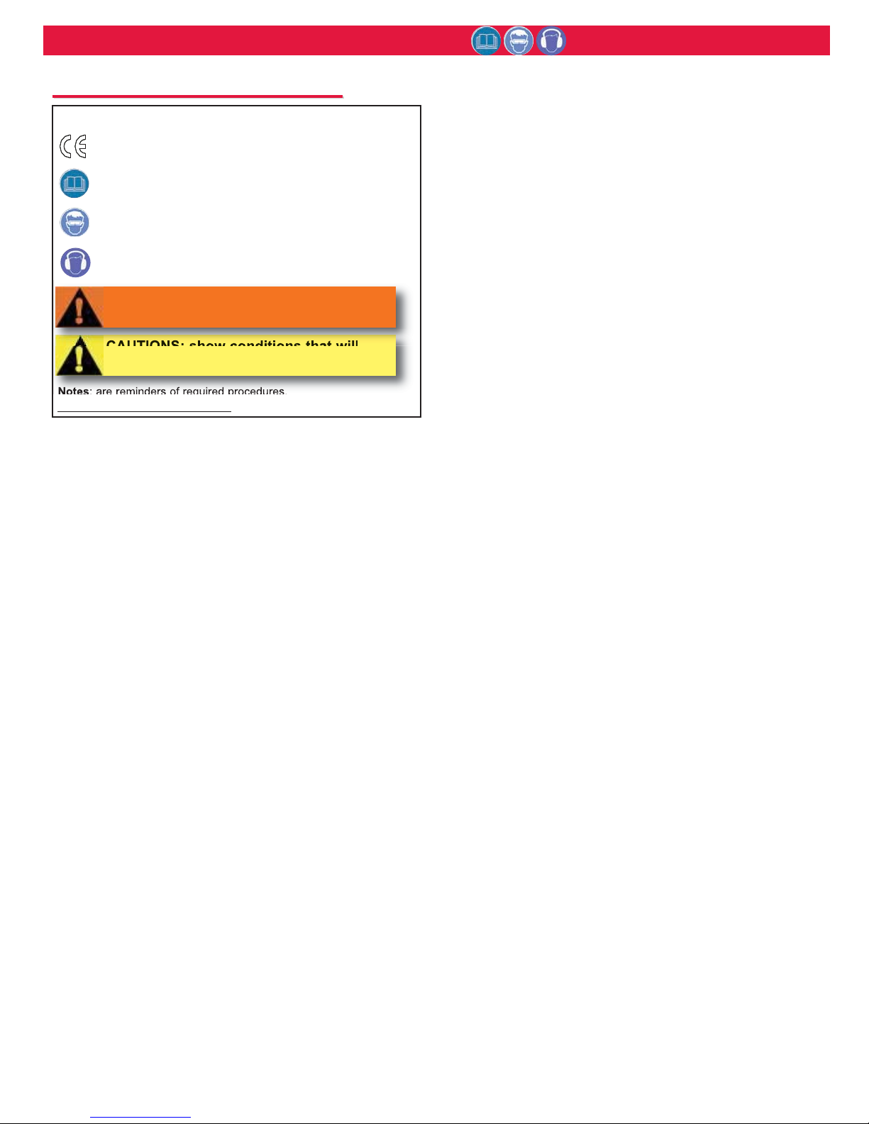
GLOSSARY OF TERMS AND SYMBOLS:
- Product complies with requirements set forth by the
relevant European directives.
- READ MANUAL prior to using this equipment.
- EYE PROTECTION IS REQUIRED while using this
equipment.
- HEARING PROTECTION IS REQUIRED while using this
equipment.
Notes: are reminders of required procedures.
Bold, Italic type and underlining
: emphasizes a specific instruction.
S
S
AFETY
AFETY
I
I
NSTRUCTIONS
NSTRUCTIONS
CAUTIONS: show conditions that will
damage equipment and or structure.
WARNINGS: Must be understood to avoid
severe personal injury.
Page 5
256BT Pneudraulic Installation Tool (HK1109) Alcoa Fastening Systems
5
Power Source: Huck POWERIG Hydraulic Unit
Hydraulic Fluid: ATF meeting DEXRON III, DEXRON IV,
MERCON, Allison C-4 or equivalent specifications.
Fire resistant hydraulic fluid may also be used and is
required to comply with OSHA regulation 1926.302
paragraph (d): "the fluid used in hydraulic power tools shall
be fire resistant fluid approved under schedule 30 of the
US Bureau of Mines, Department of Interior, and shall
retain its operating characteristics at the most extreme
temperatures to which it will be exposed."
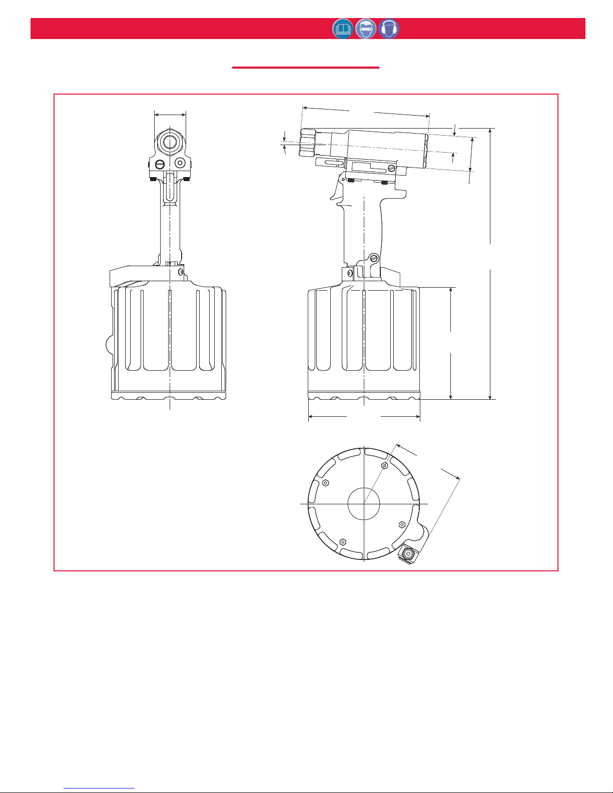
• Stroke: 1.275 in (3.24 cm)
• Weight: 11 lbs (5 kg)
• Max Air Pressure: 90 psi (6.2 BAR)
• Max Flow Rate: 22.4 scfm
• Capacity: 6700 lbs (29.8 kN) @ 90 psi (6.2 BAR)
• Speed/Cycles: 30 per minute
• Max Operating Temp: 125°F (52°C)
S
S
PECIFICATIONS
PECIFICATIONS
1.50
(38)
INCHES
(mm)
4°
6.99
(177.6)
HUCK
U
.
S
.
P
A
.93
(23.7)
256BT
T.
4
5
9
7
2
6
3
1.86
ø
(47.3)
14.85
(377.2)
6.15
(156.3)
6.13
ø
(155.6)
3.98
(101.1)
Page 6
256BT Pneudraulic Installation Tool (HK1109) Alcoa Fastening Systems
6
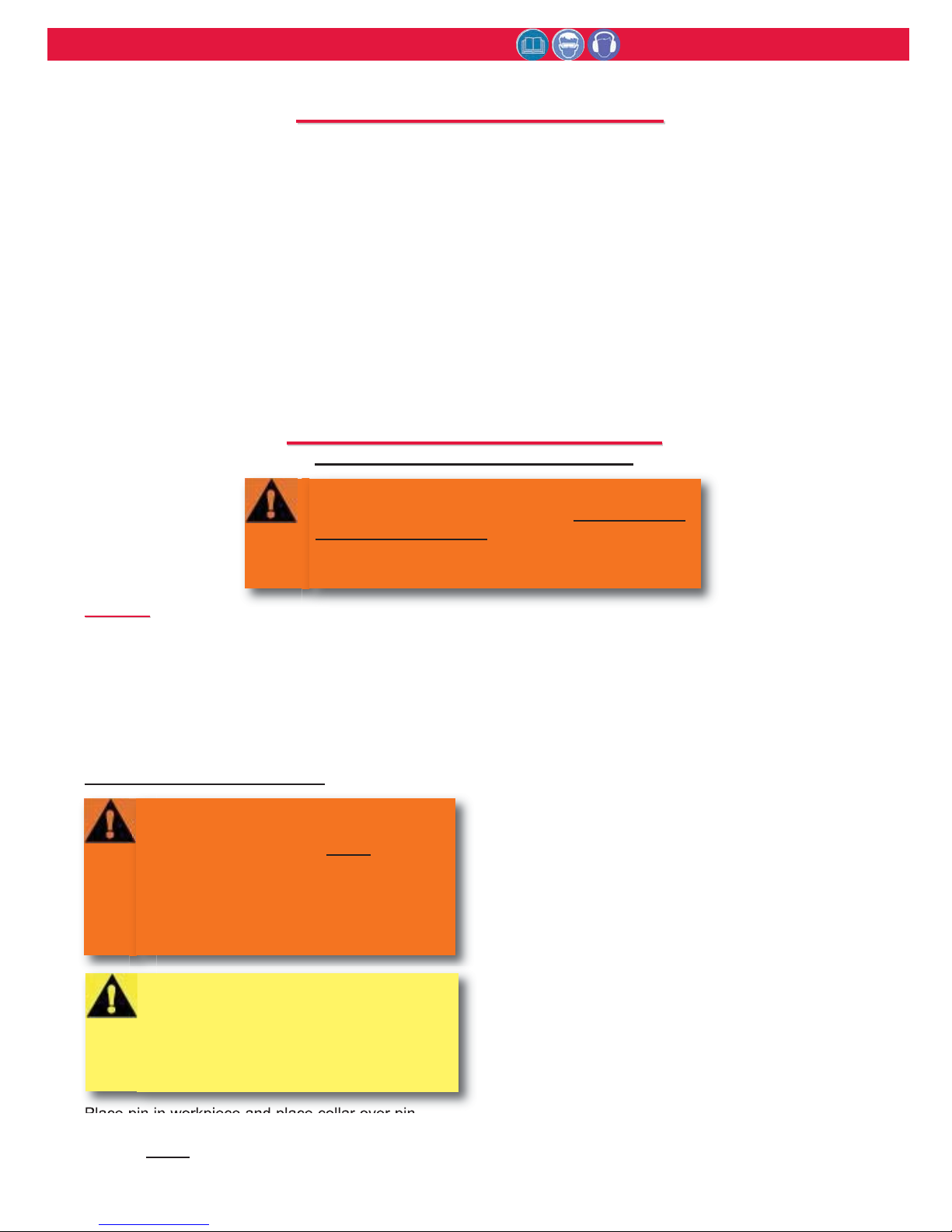
When the trigger is depressed the throttle valve
moves to down position, pressurized air is directed
to the bottom of the air piston, causing the piston to
move upward. The air above the piston is exhausted
and directed through the center of the throttle valve
and out the bottom of the tool . The air piston has a
rod and a hydraulic piston attached. When the air
piston rod moves upward, a column of pressurized
fluid is forced into head, which moves the pull piston
back. The attached nose assembly moves with the
pull piston spindle to start fastener installation.
When fastener installation is completed, the trigger
is released. Air pressure with the assistance of a
spring causes the throttle valve to return to its up
position. Pressurized air is re-directed to the top of
the air piston, causing the piston to move downward.
The air from below the piston is exhausted through
bottom of tool. The rod and hydraulic piston move
downward; hydraulic pressure is reversed and the
pull piston is returned forward. Return pressure
relief valve protects tool against pressure spikes. The
reservoir replenishes hydraulic system as needed.
P
P
RINCIPLE
RINCIPLE
OF
OF
O
O
PERATION
PERATION
O
O
PERATING
PERATING
I
I
NSTRUCTIONS
NSTRUCTIONS
For safe operation. Please read completely
WARNINGS:
●To avoid severe personal injury: Wear approved
eye and ear protection.
● Be sure of adequate clearance for Operator’s
hands before proceeding with fastener installation.
G
G
ENERAL
ENERAL
Operators should receive training from qualified
personnel.
Do not bend tool to free if stuck.
Tool should only be used to install fasteners.
NEVER use as a jack/spreader or hammer.
BOBTAIL® Fastener Installation:
Place pin in workpiece and place collar over pin.
See WARNING. (If Collar has only one tapered end,
that end MUST
be out toward tool; not next to
sheet.) Hold pin and push nose assembly onto pin
protruding through collar until nose anvil touches
collar. Depress trigger and hold until collar is
swaged and pintail breaks. Release trigger. Tool will
go into its return stroke. Tool/nose are ready
for next installation cycle.
• Length of tool increases during fastener
installation. Allow adequate tool and anvil
clearance before installing fasteners.
• Check pin for correct grip. Place pin in work
hole.
• Place collar over pin. See WARNINGS. If collar
has only one tapered end, that end should be
outward toward tool.
• Hold pin in hole. Push tool onto pin protruding
from collar until anvil touches collar.
• Move hands away from pin and structure. Keep
hands away from front of tool during operation.
Tool anvil advances forward.
• Hold tool at right angle (90 degrees) to work.
Press and hold trigger down until collar is
swaged.
• Release trigger. Tool returns to starting position.
• Tool is ready for next installation cycle.
WARNING: Do not pull on a pin without
placing fastener/collar in a workpiece,
and also, collar chamfer MUST be out
toward tool. These conditions cause pin
to eject with great velocity and force
when the pintail breaks off or
teeth/grooves strip. This may cause
severe personal injury.
CAUTIONS: Remove excess gap from
between the sheets. This permits enough
pintail to emerge from collar for ALL jaw
teeth to engage with pintail. If ALL teeth
do not engage properly, jaws will be
damaged.
Page 7
256BT Pneudraulic Installation Tool (HK1109) Alcoa Fastening Systems
7
G
G
ENERAL
ENERAL
1. The efficiency and life of any tool depends upon
proper maintenance. Regular inspection and
correction of minor problems will keep tool
operating efficiently and prevent downtime. The tool
should be serviced by personnel who are
thoroughly familiar with how it operates.
2. A clean, well lit area should be available for
servicing the tool. Special care must be taken to
prevent contamination of pneumatic and hydraulic
systems.
3. Proper hand tools, both standard and special, must
be available.
4. All parts must be handled carefully and examined
for damage or wear. Always replace Seals, when
tool is disassembled for any reason. Components
should be disassembled and assembled in a
straight line without bending, cocking, or undue
force. Disassembly and assembly procedures
outlined in this manual should be followed.
5. Service Parts Kit includes consumable parts and should
be available at all times. Other components, as experience
dictates, should also be available.
D
D
AILY
AILY
1. If a Filter-Regulator-Lubricator unit is not being
used, uncouple air disconnects and put a few drops
of Automatic Transmission Fluid or light oil into the
air inlet of the tool. If the tool is in continuous use,
put a few drops of oil in every two to three hours.
2. Bleed the air line to clear it of accumulated dirt or
water before connecting air hose to the tool.
3. Check all hoses and couplings for damage or air
leaks, tighten or replace if necessary.
4. Check the tool for damage or air/hydraulic leaks,
tighten or replace if necessary.
5. Check the nose assembly for tightness or damage,
tighten or replace if necessary.
6. Check oil level in tool reservoir, replenish if
necessary.
W
W
EEKLY
EEKLY
1. Disassemble and clean nose assemblies and
reassemble per applicable Nose Assembly Data
Sheet.
2. Check the tool and all connecting parts for damage
or oil/air leaks, tighten or replace if necessary.
M
M
AINTENANCE
AINTENANCE
WARNING: Inspect tool for damage or
wear before each use. Do not operate if
damaged or worn, as severe personal
injury may occur.
CAUTIONS:
●Consult MSDS before servicing tool.
●Keep dirt and other material out of
hydraulic system.
●Separated parts most be kept away from
dirty work surfaces.
●Dirt/debris in hydraulic fluid causes
Dump Valve failure in Tool and in
POWERIG® Hydraulic Unit’s valves.
CAUTION: Do not use TEFLON®* tape on
pipe threads. Pipe threads may cause tape
to shred resulting in tool malfunction.
(Slic-Tite is available in stick form as Huck
P/N 503237.)
CAUTION: Always replace seals, wipers,
and back-up rings when tool is
disassembled for any reason.
Note:
See SS
PECIFICATIONS
PECIFICATIONS for fluid type. Dispose of
fluid in accordance with local environmental
regulations. Recycle steel, aluminum, and plastic
parts in accordance with local lawful and safe
practices.
Page 8
256BT Pneudraulic Installation Tool (HK1109) Alcoa Fastening Systems
8
D
D
ISASSEMBLY
ISASSEMBLY
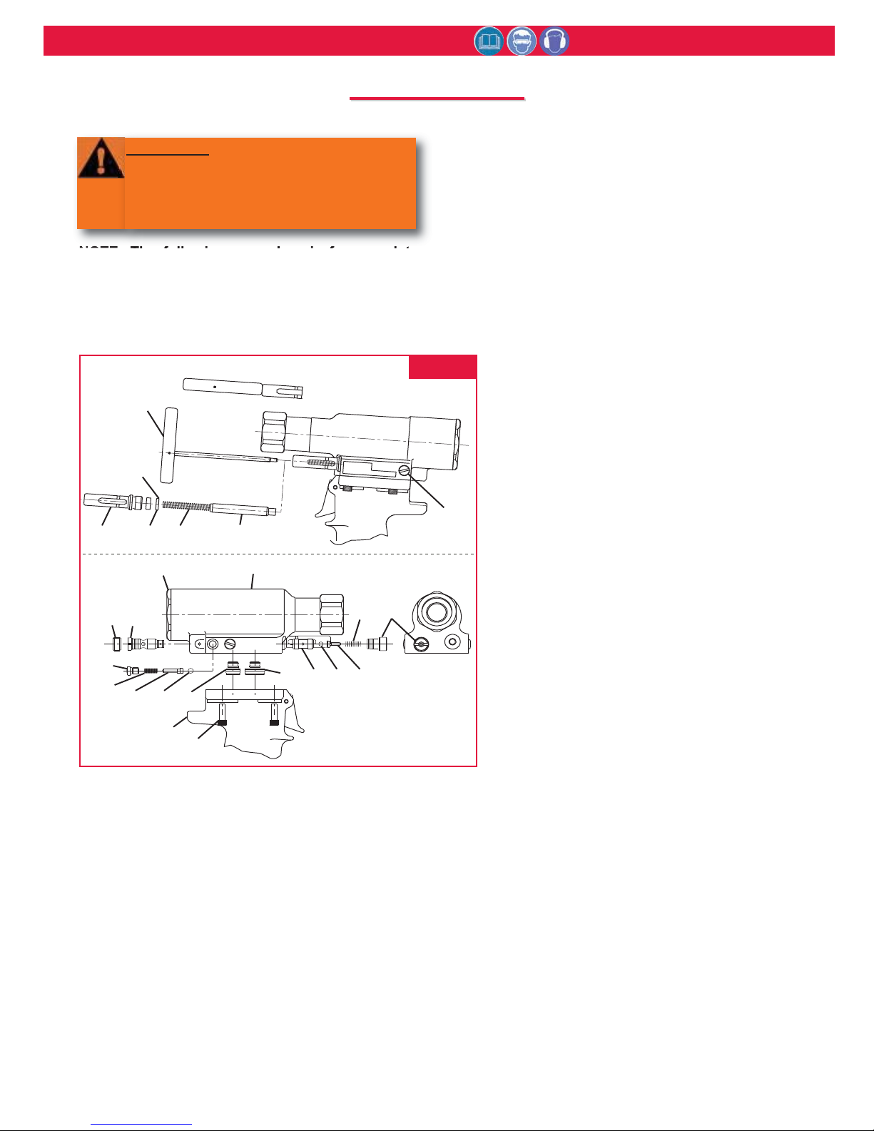
NOTE: The following procedure is for complete
disassembly of tool. Disassemble only those
components necessary to replace damaged Orings, Quad-Rings, Back-up Rings, and worn or
damaged components. Always use soft jaw vice to
avoid damage to tool.
1. Disconnect air hose from tool.
2. Remove nose assembly.
3. Insert Fill Tool part no. 112465 through reservoir
housing and screw into Reservoir Plunger (42)
locking it in the out position. Figure 1
4. Unscrew Cap Screws (32) with 5/32 hex key.
Carefully lift Head (9) straight up from Handle (1),
remove Pull Gland Assy (31) and Return Gland
Assy (15) from separated Head and Handle
assembly. Remove seals from glands. Figure 1
5. Unscrew Plug (57) of return Pressure Relief Valve
from front of head. Remove Spring (56), Valve
Guide (54), Sleeve (55) and Steel Ball (53). A
small magnet is helpful. Figure 1
6. Unscrew Bleed Plug (33). Hold over waste oil
container and release fill tool slowly. Figure 1
7. Unscrew Reservoir Housing (40) from head.
Remove two Springs (39). Slide Reservoir
Plunger (42) from head. Remove spacer and
Quad Ring (41). A pick may be used to remove
the quad ring. Figure 1
8. Unscrew Plug (50) of reservoir check valve from
side of head. Remove Spring (45), Check Valve
Guide (44) and Stainless Steel Check Valve Ball
(43). Figure 1
9. If Check Valve Seat (52) is damaged contact
your Huck representative. If Seat (52a) is
damaged it can be removed by using the
following procedure. NOTE: If seat is taken
out it cannot be reused; it must be
replaced. Figure 9
10. Seat Assy (52) Removal: NOTE: All parts in
the reservoir check valve must be removed
before Plug (51) can be removed. Using a
3/16 Allen wrench, remove Screw (46). Insert
a #10 screw in the thread of Plug (51). Pull to
remove. Using optional Seat Removal Tool
p/n 126136 or a small drift and hammer, from
the rear side of the head, drive Seat Assy (52)
out towards the front of the head. Figure 9
11. Unscrew Cylinder Cap (13) from Head (9)
with 1 11/16 open end wrench. Unscrew
Cylinder Cap (13) from Head (9) with with 1
11/16 open end wrench.
12. Remove Piston (11) through rear of tool.
NOTE: Piston should push out front and
rear gland assemblies.
13. Remove two Screws (34) from Throttle Arm
Guard (37) and remove guard.
14. Remove Screw (35) from Throttle Arm (36).
Remove throttle arm. Pull Throttle Valve (17a) out
of cylinder. Remove Spring (17d). Figure 9
15. With a small punch and hammer, drive Roll Pin (5)
that retains the trigger from Handle (1). Remove
Trigger Pin (4). Remove ball end of cable (2) from
Throttle Arm (36), and pull cable out of handle.
Figure 9
16. Remove Bleed Plug (33) from handle. Figure 1
FIG. 1
WARNING
Be sure air hose is disconnected from
tool before cleaning, or performing
maintenance. Severe personal injury may
occur if air hose is not disconnected.
Lock-out Position
FILL TOOL
112465
HUCK
256BT
U.S. PA
T
SPACER
51
46
13
4239(2)4140
9
. 4597263
56 57
33
50
45
15
4344
1
(4)
32
31
55 53 54
Page 9
256BT Pneudraulic Installation Tool (HK1109) Alcoa Fastening Systems
9
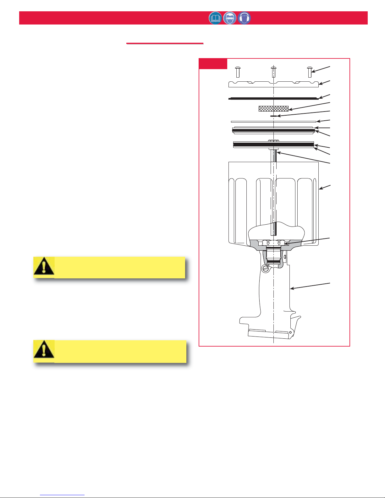
17. Hold tool inverted in vice. Unscrew four Button
Head Screws (18) with 1/8 hex key. (Fig. 3)
18. Remove Muffler End Cap (20), Bottom Exhaust
Gasket (23), Muffler (21) and O-ring (22). (Fig. 3)
19. Remove Retaining Ring (24) from Cylinder
Assembly (28). (Fig. 3) NOTE: Tap cylinder head
down into cylinder for easier removal of retaining
ring.
20. Screw Button Head Screws (18) into Cylinder Head
(25a). Carefully pry under screws to remove
cylinder head.
21. Push air piston all the way down in cylinder and lay
tool on its side. Hold Self-locking Nut (19) with a
9/16 socket and extension and, with 7/64 hex key,
remove piston Screw (30b). (Fig. 4 & 9)
22. Return cylinder and handle to upside down
position, and secure in a vise.
23. Grip Self-locking Nut (19) under Air Piston (26) with
pliers and pull piston and rod assembly from
handle and cylinder assembly. (Fig. 3 & 4)
24. With a 1 3/8 socket and extension, remove Gland
Assembly (29). Handle and cylinder will now
separate. (Fig. 3)
25. Push Hydraulic Piston (31) out of handle. Push out
from top to bottom.
26. To remove Polyseal (29e) from Gland Assembly
(29). Remove Retaining Ring (29k) and Spacer
(29a). (Fig. 9)
D
D
ISASSEMBLY
ISASSEMBLY (continued)
CAUTION: Care must be taken not to
scratch piston rod or cylinder during
removal.
CAUTION: A plastic or wooden drift must
be used to avoid damaging the handle
bore.
FIG. 3
18
20
23
21
22
24
25a
25b
26b
26a
27
28
29
1
Page 10
256BT Pneudraulic Installation Tool (HK1109) Alcoa Fastening Systems
10
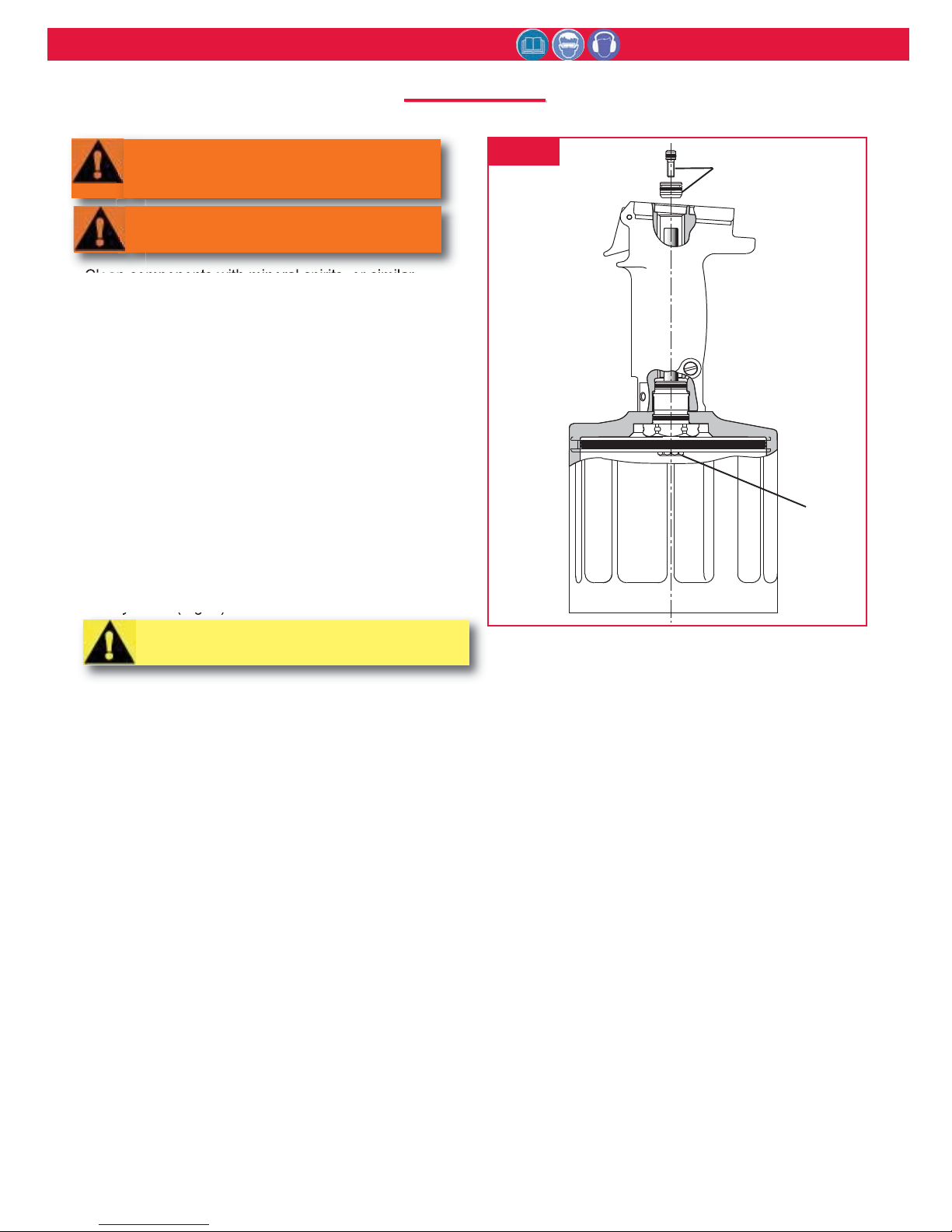
Clean components with mineral spirits, or similar
solvent. Inspect for wear/damage and replace as
necessary. Replace all seals of disassembled
components. Use O-rings, Quad rings and Back-up
rings in Service Parts Kit, P/N 256BTKIT Smear
LUBRIPLATE 130AA or PARKER-O-LUBE on O-rings,
Quad rings, Back-up rings and mating parts to ease
assembly. Assemble tool taking care not to damage
O-rings, Quad rings, or Back-up rings.
1. Holding handle inverted in a vice, Place Cylinder
(28) on handle with Timing Pin positioned in
matching hole. Assemble Gland Assembly (29)
and screw it into handle. (Fig. 9) Torque to 100 120 ft. lbs. using 1 3/8 socket wrench.
2. Push Air Piston/Rod assembly with Quad Ring
(26b) in place into air cylinder until it reaches top of
cylinder. (Fig. 3)
3. Turn tool upright. Install Hydraulic Piston
Assembly (30) (with O-ring (30c) and Back-up
Rings (30d) in place) in handle. Press in from top
of handle taking care not to damage seals. (Fig. 4)
4. Push Screw (30b) with O-ring (30e) in place
through Hydraulic Piston (30a) and screw into top
of piston rod. Hold Nut (19) with 9/16 socket and
extension and torque Screw (30b) using 7/64 hex
key to 55 - 60 in. lbs.
5. Hold handle in vise with bottom facing up. Push
Cylinder Head (25a) with O-ring (25b) in place
squarely into cylinder. Install Retaining Ring (24).
(Fig. 3 & 9)
6. Position O-ring (22) and Muffler (21) on center of
Cylinder Assy (25). Place Gasket (23) on Cylinder
Assembly (28). NOTE: Lip must face Muffler End
Cap (20). Place Muffler End Cap (20) on top of
Gasket (23), and secure with 3 Button Head
Screws (18) using 1/8 hex key. (Fig. 3)
7. Turn tool upright. Drop Spring (17d) into Throttle
Valve hole in cylinder. Push Throttle Valve (17a)
with O-rings (17b & 17c) in place into cylinder. (Fig.
9)
8. Assemble Trigger (3) Cable (2) and Trigger Pin (4),
and slide cable into Handle (1). Align hole in
trigger with hole in handle and install Roll Pin (5)
with a hammer and punch. (Fig. 9)
9. Slide Throttle Arm (36) onto ball end of throttle
cable. Swing arm until other end fits over throttle
valve. Push Screw (35) through Throttle Arm (36).
Tighten with 5/32 hex key.
10. If Air Hose Assembly (38) was removed, reinstall in
Cylinder Assembly (28).
11. {If Seat Assy (52) is being replaced}: Push Plug
(51) (with O-ring 48 & Back-up Ring 47 in place)
into head. Install Screw (46). (Fig. 9)
12. Install O-ring (52c) and Back-up Rings (52b ) onto
Seat (52a). Drive Seat Assy (52) in using soft drift
taking care not to damage Relief Valve Ball (53)
surface. (Fig. 9, Section A-A)
13. Assemble Pull Piston (11a) with new Seals (11b &
11c). Lubricate with LUBRIPLATE or PARKER
SUPER-O-LUBE and install. (Fig. 9 & 10)
14. Push Front Gland Assy (10) with all seals, housing
and wiper in place (Figure 2) over Assembly Bullet
and onto Pull Piston Assy (11). (Fig. 9 & 10)
A
A
SSEMBLY
SSEMBLY
CAUTION: Do NOT scratch piston rod.
WARNING: Do not omit any seals during
servicing, leaks will result and personal
injury may occur.
WARNING: Tool must be fully assembled
with all components included.
FIG. 4
30
Piston
Assembly
19
Page 11
256BT Pneudraulic Installation Tool (HK1109) Alcoa Fastening Systems
11
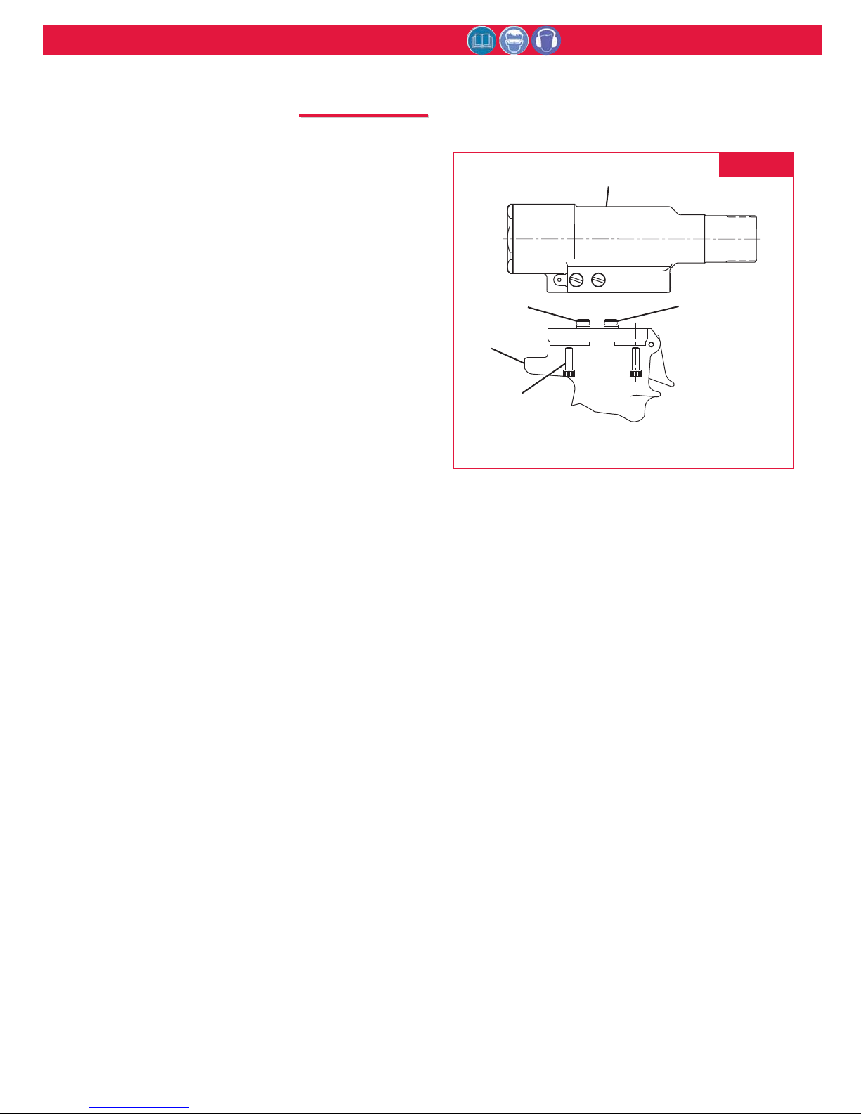
15. Install O-rings (12d & 12b) and Back-up Rings (12e
& 12c) on Rear Gland (12a). Push complete
assembly into head. Screw in End Cap (13) and
tighten. (Fig. 9 & 10)
16. Install O-ring (48) & Back-up Ring (47) on Plug (57).
Install Ball (53), Valve Guide (54), Sleeve (55),
Spring (56) and Plug (45) into head. (Fig. 1 & 9)
17. Install O-ring (49) on Plug (50). Install Check Valve
Ball (43), Check Valve Guide (44), Spring (45) and
Plug (50) into head.
18. Push Pintail Deflector (14) onto barbed end of Pull
Piston (11a). (Fig. 9)
19. Place O-rings (33b) on Bleed Plugs (33a) and screw
assemblies into Handle (Qty. 1) and Cylinder Head
(Qty. 2). (Fig. 9)
20. Install O-rings (31c & 31e) & Back-up Rings (31b &
31d) on Pull Gland (31a). Install O-rings (15c & 15d)
and Back-up Rings (15b & 15e) on Return Gland
(15a). Push Gland Assemblies (15 & 31) into handle.
Push Head (9) down on glands. Place tool in a vise,
head down, and install 4 Screws (32) and torque to
170 inch pounds. (Fig. 5)
21. Tool is now completely assembled and ready for Fill
& Bleed.
A
A
SSEMBLY
SSEMBLY (continued)
FIG. 5
9
15
1
32(4)
31
Page 12
256BT Pneudraulic Installation Tool (HK1109) Alcoa Fastening Systems
12
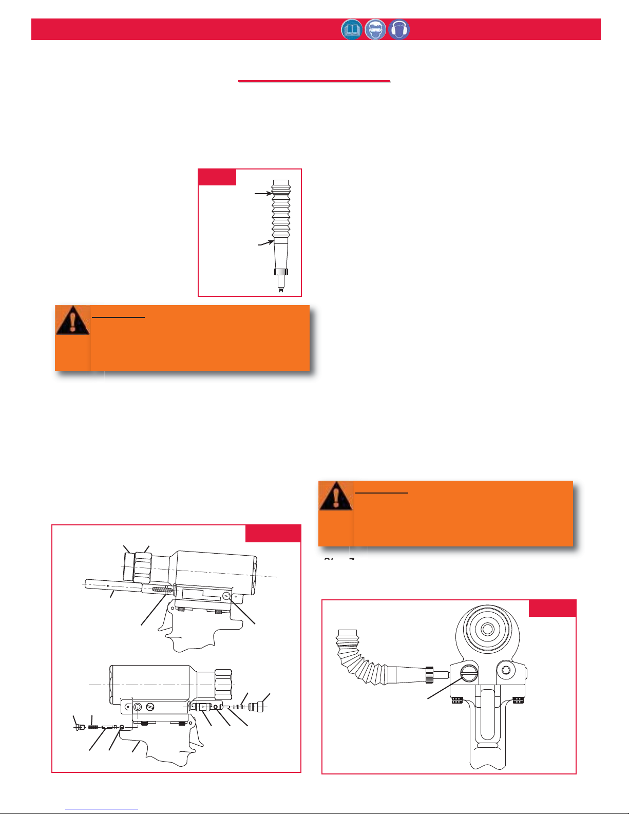
Equipment Required:
- Shop airline with 90 - 100 psi max.
- Air regulator
- Fill bottle, 120337, (supplied with tool).
- Large flat blade screwdriver
- Optional Stall Nut 120824
- Nose assembly
- Fasteners (Optional)
Preparation:
1. Install air regulator in
airline and set pressure to
20-40 psi.
2. Fill bleed bottle almost full
of DEXRON III - ATF or
equivalent. (Fig.6)
Refill tool only when red line on plunger drops below the
red line on the reservoir housing or when tool is rebuilt.
USE: AUTOMATIC TRANSMISSION FLUID DEXRON
III, OR EQUIVALENT.
Step 1
Screw Fill Tool into Reservoir Plunger, pull Plunger into
Housing and lock Fill Tool in full forward position by
tilting handle (long side touching tool) and locking in
place. (Fig. 7)
Step 2
Remove Plugs (57) and (50) and all guides, springs and
balls from ports in head. Reinstall Plug (57) in head in
Relief Valve port (front of tool). (Fig. 7 & 8).
Step 3
Screw retaining nut onto head assembly. Screw Stall
Nut (optional see note:) onto Piston and tighten to
ensure full thread engagement. Back off retaining nut
until it engages stall nut. Check Piston location. Piston
must be all the way forward and locked with stall nut
and retaining nut. Note: If Stall Nut is not used, piston
must be pushed to the full forward position before
installing valves.
Step 4
Attach the tool air source momentarily to seat air piston
at bottom of cylinder. Disconnect tool. With fill port
facing up, (check valve on side) lay tool on its side.
Step 5
Install fill bottle in head fill port (check valve hole).
(Fig. 7 & 8)
Step 6
Connect tool to shop air regulated to 20 to 40 psi. Cycle
tool 20-30 times. Watch for air bubbles escaping from
the tool into bottle. (You may rock the tool to free
trapped air in the tool.) Do not allow the air to re-enter
the tool.
Step 7
When air bubbles no longer appear in bottle, remove fill
bottle while tool is lying on its side.
FIG. 7
FILL
POINT
120337
Fill Bottle
Assembly
FIG. 6
FIG. 8
WARNING: Avoid contact with hydraulic
fluid. Hydraulic fluid must be disposed of
in accordance with Federal, State and Local
Regulations. Please see MSDS for
Hydraulic fluid shipped with tool.
WARNING: Air pressure MUST be set to 20
to 40 psi to prevent possible injury from
high pressure spray. If plug (50) is
removed, fill bottle must be in place before
cycling tool.
F
F
ILL
ILL
AND
AND
B
B
LEED
LEED
Stall Nut
120824
Fill Tool
8
256/257
HUCK
U.
S
.
P
AT
.
4
5
9
7
2
6
3
Red Line
Indicator
45
50
44 43
1
33
56
57
57
5355
54
Page 13
256BT Pneudraulic Installation Tool (HK1109) Alcoa Fastening Systems
13
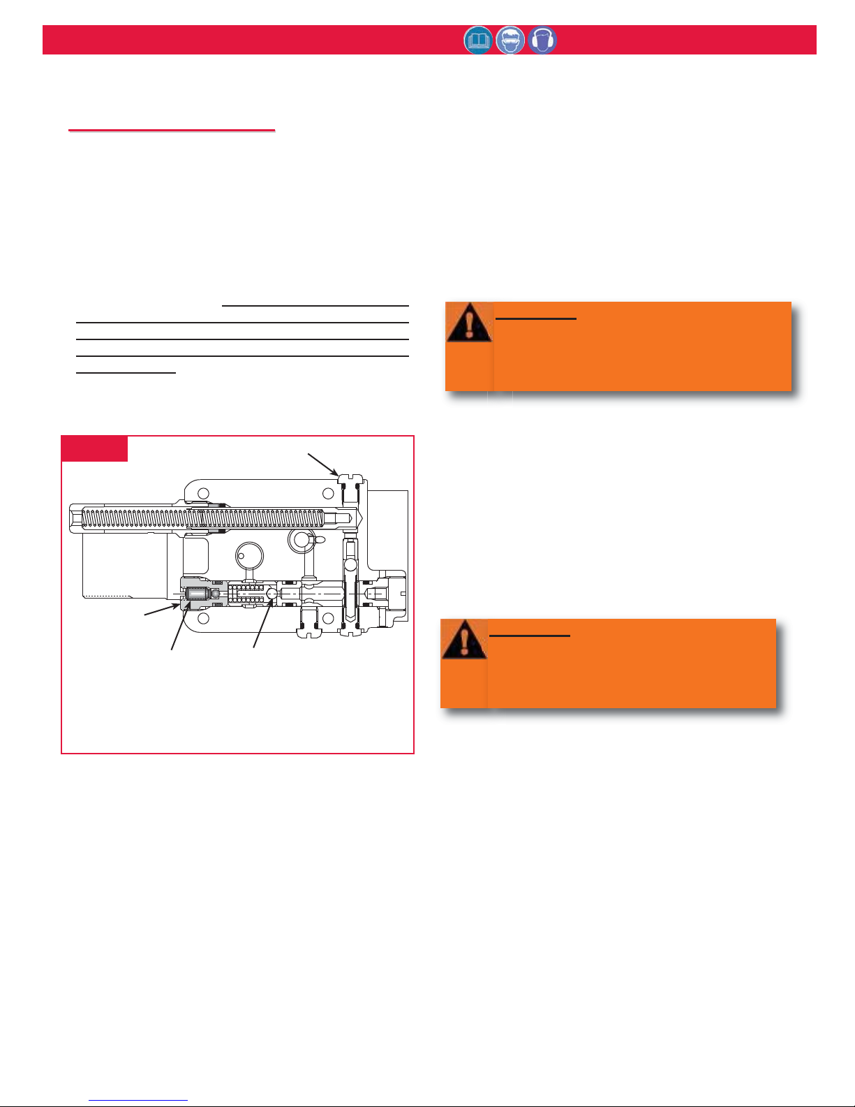
Step 8
Install the check valve Ball (43), Guide (44) and Spring
(45). Replace the Plug (50). (Fig. 7) Note: When
cycling tool, always hold bottle up as shown in Figure
8 to prevent drawing in air from empty part of bottle.
Step 9
Turn tool so front of head faces you and remove the
Relief Valve Plug (57). Prior to removing Plug (57), it
is advisable to back out setscrew inside of plug by
approximately 1/2 turn counterclockwise. (See Figure
8a). This ensures that the Piston will remain in fullforward position. Install Relief Valve Ball (53), Guide
(54), Sleeve (55) and Spring (56). Replace the Relief
Valve Plug (57) and, after bleeding, re-tighten
setscrew.
Step 10
Unlock Fill Tool and check Reservoir red line. At this
point cycle tool with Stall Nut attached (Optional. See
note) and retaining nut locked in the full forward
position (“Dead Stall”). Reservoir should not drop
below the red line on the reservoir housing. NOTE:
Dead Stalling is not necessary if Optional Stall nut was
not used; just cycle tool.
Step 11
Re-lock the fill tool in out position. Lay tool on its side
with the reservoir on the high side, and remove Bleed
Plug (33) from the reservoir side. Top off reservoir by
placing a few drops of oil in hole and wait for air
bubbles to escape. Push a pin or a scribe into hole to
check for trapped air bubbles. Replace plug. (Figs. 7 &
8a)
Step 12
Unlock the fill tool and cycle tool as in step 10.
Reservoir may drop slightly. If so, repeat step 11 until,
when you touch the fill tool handle, it has no pressure
against it and it drops out of the lock position, and the
plunger does not drop when tool is cycled. NOTE:
This usually requires 3 to 4 times topping off.
Step 13
Remove fill tool and stall nut (if used). Install a nose
assembly and pull several fasteners to test function.
FIG. 8a
F
F
ILL
ILL
AND
AND
B
B
LEED
LEED (CONTINUED)
WARNING
Failure to re-lock the fill tool will result in oil
being ejected from the head under pressure
during the topping off of the reservoir.
Severe personal injury may result.
WARNING
Air pressure MUST be set to 20 to 40 psi to
prevent possible injury from high pressure
spray. If plug (78) is removed, fill bottle
must be in place before cycling tool.
33 - Bleed
Plug
57 - Relief
Valve Plug
Using a 3/32 Allen
wrench, loosen
setscrew inside Plug by
approx. 1/2 turn.
53 - Relief
Valve Ball
SECTION A-A
from Figure 9
Page 14
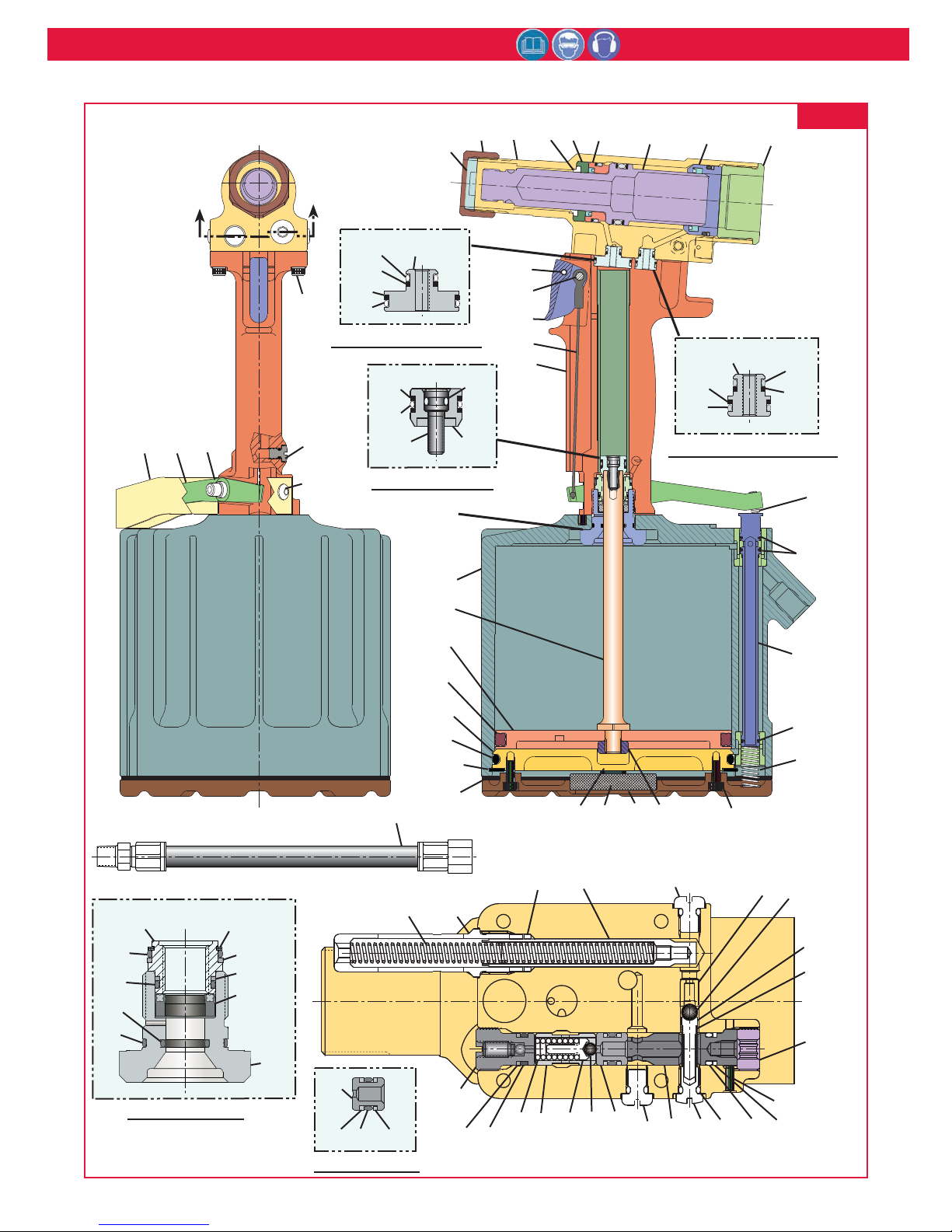
256BT Pneudraulic Installation Tool (HK1109) Alcoa Fastening Systems
14
FIG. 9
6
9a
8
14
7
10
11
12
13
37
A
A
31b
31c
31d
32
31e
31 - Pull Gland Assy
30d
(2)
31a
30e
5
4
3
2
1
15e
15a
15b
15c
15d
30c
3536
33
34
30b
30a
30 - Piston Assy
15 - Return Gland Assy
16
29
(See detail
below.)
Shown without
Throttle Guard
17
b
28
27
26a
17
a
26b
29a
29h
29g
29f
29j
29 - Gland Assy
29k
29c
29d
29e
(Note
orientation
of polyseal)
29b
38
39
52a
52b
52c
52b
52 - Seat Assy
25a
25b
24
23
40
57
47
48
56
41
55
54
SECTION A-A
17
c
17
d
19
20
2122
3342
18
9b
43
44
45
46
9c
5253
33
51
50
49
48
47
Page 15
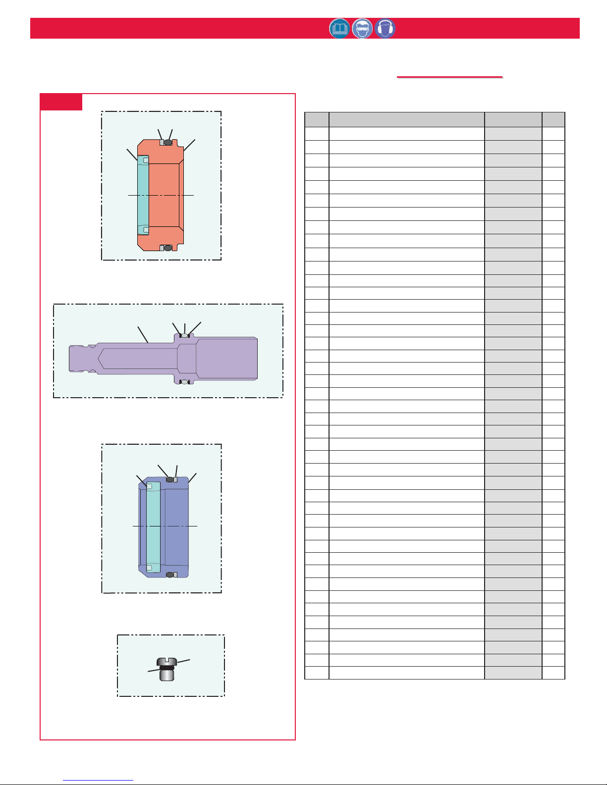
256BT Pneudraulic Installation Tool (HK1109) Alcoa Fastening Systems
15
Item Description Part No. Qty.
1 Handle & Sleeve Assy 125642 1
2 Cable 125643 1
3 Trigger 124333-2 1
4 Trigger Pin 505496 1
5 Roll Pin 500621 1
6 Wiper Housing 129549 1
7 Stop 110670 1
8 Retaining Nut 117824 1
9 Head Assy contains: 129552 1
9a
Cylinder Head *
n/a 1
9b Seat 111139 1
9c Pin 120203 1
10 Front Gland Assy contains: 129556 1
10a
Front Gland *
n/a 1
10b Polyseal 505865 1
10c O-Ring 500820 1
10d Back-up Ring 501114 1
11 Pull Piston Assy contains: 129555 1
11a
Pull Piston *
n/a 1
11b Back-up Ring 501144 2
11c O-Ring 500850 1
12 Rear Gland Assy contains: 129557 1
12a
Rear Gland *
n/a 1
12b O-Ring 505887 1
12c Back-up Ring 501118 1
12d Polyseal 508428 1
13 Cylinder Cap 129550 1
14 Wiper 505894 1
15 Return Gland Assy contains: 112502 1
15a
Return Gland *
n/a 1
15b O-Ring 500776 1
15c Back-up Ring 501082 1
15d O-Ring 500778 1
15e Back-up Ring 501084 1
16 Throttle Arm Setscrew 502053 1
17 Throttle Valve Assy contains: 115558 1
17a
Throttle Valve *
n/a 1
17b O-Ring 504408 2
17c O-Ring 504407 1
17d Spring 116272 1
18 Button Head Screw 500101 4
19 Self-locking Nut 121241 1
20 Muffler End Cap 120076 1
FIG. 10
* When replacing these parts, the assembly must be
ordered. They are not sold separately.
Parts list continued on next page.
P
P
ARTS
ARTS
L
L
IST
IST
(Refer to Figures 9 and 10)
10d
10c
10a
10b
10 - Front Gland Assy
11b
11c
12b
11b
12c
12a
33a
11a
11 - Pull Piston Assy
12d
12 - Rear Gland Assy
33b
33 - Bleed Plug / O-Ring Assy
Page 16
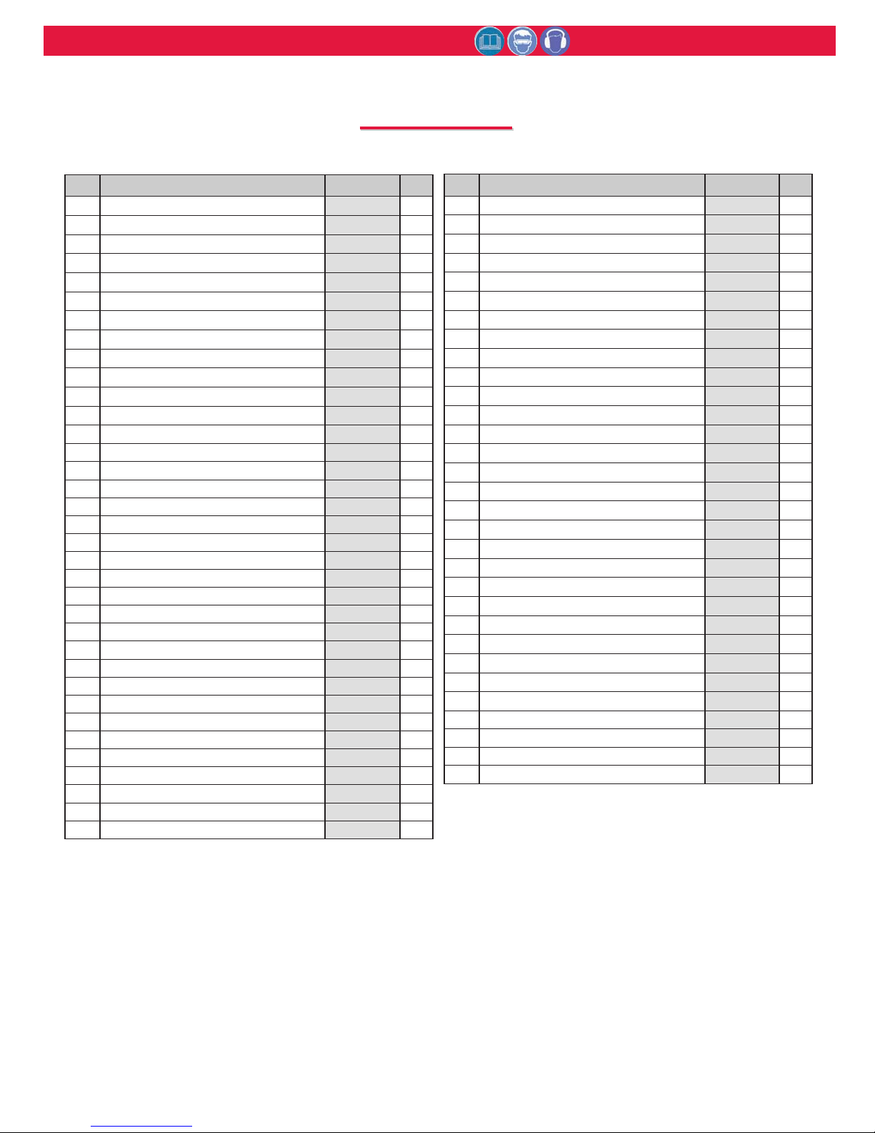
256BT Pneudraulic Installation Tool (HK1109) Alcoa Fastening Systems
16
Item Description Part No. Qty.
32 Cap Screw 500102 4
33 Bleed Plug / O- Ring Assy contains: 104243 3
33a
Bleed Plug *
n/a 1
33b O-Ring 505438 1
34 Screw 502482 2
35 Screw & Bushing Assy 127029 1
36 Throttle Arm 127688 1
37 Guard 125657 1
38 Air Hose Assy 115436 1
39 Spring 505864 2
40 Housing / Spacer Assy 112403 1
41 Quad Ring 501408 1
42 Reservoir Plunger 112405 1
43 Check Valve Ball 502929 1
44 Check Valve Guide 111067 1
45 Spring 100874 1
46 Screw 120129 1
47 Back-up Ring 501082 2
48 O-Ring 505446 2
49 O-Ring 505438 1
50 Plug 111068 1
51 Plug 120204 1
52 Seat & Seals Assy Assy contains: 114537 1
52a
Seat *
n/a 1
52b Back-up Ring 501082 2
52c O-Ring 505446 1
53 Relief Valve Ball 502506 1
54 Relief Valve Guide 120128 1
55 Sleeve 120127 1
56 Spring 505863 1
57 Relief Valve Plug 114530 1
* When replacing these parts, the assembly must be
ordered. They are not sold separately.
Item Description Part No. Qty.
21 Muffler 115554 1
22 O-Ring 500777 1
23 Gasket 126941-3 1
24 Retaining Ring 505139 1
25 Cylinder Head Assy contains: 113528 1
25a
Cylinder Head *
n/a 1
25b O-Ring 505147 1
26 Piston / Quad Ring Assy contains: 113526 1
26a
Air Piston *
n/a 1
26b Quad Ring 501472 1
27 Piston Rod 113344 1
28 Cylinder Assy 120372 1
29 Gland Assy contains: 127326 1
29a Gland 127324 1
29b Gland Housing 127325 1
29c Back-up Ring 127327 1
29d Back-up Ring 127328 1
29e Polyseal 127329 1
29f O-Ring 500779 1
29g O-Ring 500781 1
29h O-Ring 500784 1
29j O-Ring 500786 1
29k Retaining Ring 502821 1
30 Hydraulic Piston Assy contains: 118866 1
30a
Hydraulic Piston *
n/a 1
30b Screw 117773 1
30c O-Ring 503770 1
30d Back-up Ring 501086 2
30e O-Ring 500773 1
31 Pull Gland Assy contains: 113532 1
31a
Pull Gland *
n/a 1
31b O-Ring 500776 1
31c Back-up Ring 501082 1
31d Back-up Ring 501090 1
31e O-Ring 500784 1
P
P
ARTS
ARTS
L
L
IST
IST
(Refer to Figures 9 and 10)
Page 17
256BT Pneudraulic Installation Tool (HK1109) Alcoa Fastening Systems
17
M
M
EASURING
EASURING
T
T
OOL
OOL
S
S
TROKE
TROKE
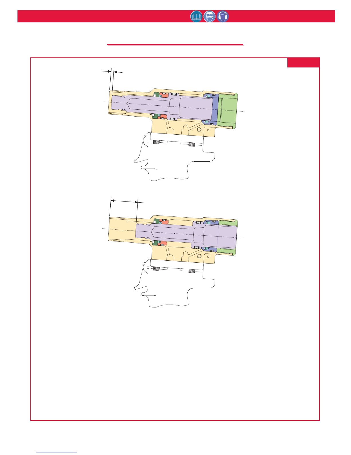
FIG. 11
1. With the Piston in the fully forward position, measure DISTANCE A from face of the Cylinder to the
face of the Piston.
2. Cycle tool and keep Piston in the full rearward position by keeping the trigger depressed. Measure
D
ISTANCE B as above.
3. T
OOL STROKE = DISTANCE B - DISTANCE A
DISTANCE A
DISTANCE B
Page 18

256BT Pneudraulic Installation Tool (HK1109) Alcoa Fastening Systems
18
Always check out the simplest possible cause of a
malfunction first. For example, an air hose not connected.
Then proceed logically, eliminating each possible cause until
the cause is located. Where possible, substitute known good
parts for suspected bad parts. Use this chart as an aid in
locating and correcting malfunction.
NOTE: Piston Drift is when the air piston is in the down
position, but the hydraulic pull piston is not in the full
forward position. This causes an out of sequence condition.
1 Tool fails to operate when trigger is depressed.
a) Air line not connected
b) Throttle Valve O‐rings worn or damaged.
c) Throttle valve Cable Assembly is broken.
2 Fastener installation incomplete; No broken pintail.
a) Air pressure too low
b) Air Piston Quad‐Ring worn or damaged.
c) Reservoir empty or low. See Fill and Bleed section.
d) Air in hydraulic system. See Fill and Bleed section.
e) Reservoir Springs worn or damaged
f) Check for piston drift
3 Pintail stripped and/or swaged collar not ejected.
a) Check for broken or worn jaws in nose assembly.
b) Check for loose Retaining Nut
c) Check for piston drift.
4 Tool has piston drift.
a) Loose collet crashing into the front of the anvil,
causing the relief valve to open allowing the piston to
drift. Tighten the collet and see Fill and Bleed section.
b) Worn or damaged Return Pressure Relief Valve
in tool, inspect Seat Assembly, O‐ring, Back‐up Rings,
Steel Ball and Valve Spring. Replace if necessary.
c) Worn or damaged Piston Assembly; Inspect O‐rings
and Back‐up Rings (36). Replace if necessary.
5 Hydraulic fluid exhausts with air or leaks at base of
handle.
a) Worn or damaged Gland Assembly; Inspect Polyseal,
O‐rings and Quad‐Ring. Replace if necessary.
6. Hydraulic fluid leaks at rear of Pull Piston
a) Worn or damaged Rear Gland. Inspect Polyseal and
O‐ring, and replace if necessary.
7. Hydraulic fluid leaks at front of Pull Piston.
a) Worn or damaged Front Gland. Inspect Polyseal, O‐
ring, and Back‐up Ring, and replace if necessary.
8. Pull Piston (18) will not return.
a) Throttle Valve stuck; Lubricate O‐rings.
b) Throttle Arm, Cable Assembly or Trigger binding.
9. Air leaks at air Cylinder Head (60).
a). Worn or damaged O‐ring. Replace if necessary.
T
T
ROUBLESHOOTING
ROUBLESHOOTING
A
A
CCESSORIES
CCESSORIES
Fill and Bleed Bottle ‐ 120337
Seat Removal Tool ‐ 126136
Fill Tool Assy for reservoir ‐ 112465
Stall Nut ‐ 120824
Page 19

256BT Pneudraulic Installation Tool (HK1109) Alcoa Fastening Systems
19
L
L
IMITED
IMITED
W
W
ARRANTIES
ARRANTIES
TOOLING WARRANTY:
Huck warrants that tooling and other items (excluding
fasteners, and hereinafter referred as "other items")
manufactured by Huck shall be free from defects in
workmanship and materials for a period of ninety (90)
days from the date of original purchase.
WARRANTY ON "NON STANDARD OR CUSTOM
MANUFACTURED PRODUCTS":
With regard to non-standard products or custom
manufactured products to customer's specifications,
Huck warrants for a period of ninety (90) days from
the date of purchase that such products shall meet
Buyer's specifications, be free of defects in
workmanship and materials. Such warranty shall not
be effective with respect to non-standard or custom
products manufactured using buyer-supplied molds,
material, tooling and fixtures that are not in good
condition or repair and suitable for their intended
purpose.
THERE ARE NO WARRANTIES WHICH EXTEND
BEYOND THE DESCRIPTION ON THE FACE
HEREOF. HUCK MAKES NO OTHER
WARRANTIES AND EXPRESSLY DISCLAIMS ANY
OTHER WARRANTIES, INCLUDING IMPLIED
WARRANTIES AS TO MERCHANTABILITY OR AS
TO THE FITNESS OF THE TOOLING, OTHER
ITEMS, NONSTANDARD OR CUSTOM
MANUFACTURED PRODUCTS FOR ANY
PARTICULAR PURPOSE AND HUCK SHALL NOT
BE LIABLE FOR ANY LOSS OR DAMAGE,
DIRECTLY OR INDIRECTLY, ARISING FROM THE
USE OF SUCH TOOLING, OTHER ITEMS,
NONSTANDARD OR CUSTOM MANUFACTURED
PRODUCTS OR BREACH OF WARRANTY OR FOR
ANY CLAIM FOR INCIDENTAL OR
CONSEQUENTIAL DAMAGES.
Huck's sole liability and Buyer's exclusive remedy for
any breach of warranty shall be limited, at Huck's
option, to replacement or repair, at FOB Huck's plant,
of Huck manufactured tooling, other items,
nonstandard or custom products found to be defective
in specifications, workmanship and materials not
otherwise the direct or indirect cause of Buyer
supplied molds, material, tooling or fixtures. Buyer
shall give Huck written notice of claims for defects
within the ninety (90) day warranty period for tooling,
other items, nonstandard or custom products
described above and Huck shall inspect products for
which such claim is made.
TOOLING, PART(S) AND OTHER ITEMS NOT
MANUFACTURED BY HUCK:
HUCK MAKES NO WARRANTY WITH RESPECT
TO THE TOOLING, PART(S) OR OTHER ITEMS
MANUFACTURED BY THIRD PARTIES. HUCK
EXPRESSLY DISCLAIMS ANY WARRANTY
EXPRESSED OR IMPLIED, AS TO THE
CONDITION, DESIGN, OPERATION,
MERCHANTABILITY OR FITNESS FOR USE OF
ANY TOOL, PART(S), OR OTHER ITEMS THEREOF
NOT MANUFACTURED BY HUCK. HUCK SHALL
NOT BE LIABLE FOR ANY LOSS OR DAMAGE,
DIRECTLY OR INDIRECTLY, ARISING FROM THE
USE OF SUCH TOOLING, PART(S) OR OTHER
ITEMS OR BREACH OF WARRANTY OR FOR ANY
CLAIM FOR INCIDENTAL OR CONSEQUENTIAL
DAMAGES.
The only warranties made with respect to such tool,
part(s) or other items thereof are those made by the
manufacturer thereof and Huck agrees to cooperate
with Buyer in enforcing such warranties when such
action is necessary.
Huck shall not be liable for any loss or damage
resulting from delays or nonfulfillment of orders owing
to strikes, fires, accidents, transportation companies
or for any reason or reasons beyond the control of the
Huck or its suppliers.
HUCK INSTALLATION EQUIPMENT:
Huck International, Inc. reserves the right to make
changes in specifications and design and to
discontinue models without notice.
Huck Installation Equipment should be serviced by
trained service technicians only.
Always give the Serial Number of the equipment
when corresponding or ordering service parts.
Complete repair facilities are maintained by Huck
International, Inc. Please contact one of the offices
listed below.
Eastern
One Corporate Drive Kingston, New York 12401-0250
Telephone (845) 331-7300 FAX (845) 334-7333
Outside USA and Canada
Contact your nearest Huck International Office, see
back cover.
In addition to the above repair facilities, there are
Authorized Tool Service Centers (ATSC's) located
throughout the United States. These service centers
offer repair services, spare parts, Service Parts Kits,
Service Tools Kits and Nose Assemblies. Please
contact your Huck Representative or the nearest
Huck office listed on the back cover for the ATSC in
your area.
Page 20
Americas
Alcoa Fastening Systems
Aerospace Products
Tucson Operations
3724 East Columbia
Tucson, AZ 85714
800‐234‐4825
520‐747‐9898
FAX: 520‐748‐2142
Alcoa Fastening Systems
Aerospace Products
Carson Operations
PO Box 5268
900 Watson Center Rd.
Carson, CA 90749
800‐421‐1459
310‐830‐8200
FAX: 310‐830‐1436
Alcoa Fastening Systems
Industrial Products
Waco Operations
PO Box 8117
8001 Imperial Drive
Waco, TX 76714‐8117
800‐388‐4825
254‐776‐2000
FAX: 254‐751‐5259
Alcoa Fastening Systems
Industrial Products
Kingston Operations
1 Corporate Drive
Kingston, NY 12401
800‐278‐4825
845‐331‐7300
FAX: 845‐334‐7333
Alcoa Fastening Systems
Industrial Products
Latin America Operations
Avenida Parque Lira. 79‐402
Tacubaya Mexico, D.F.
C.P. 11850
FAX: 525‐515‐1776
TELEX: 1173530 LUKSME
Far East
Alcoa Fastening Systems
Industrial Products
Australia Operations
14 Viewtech Place
Rowville, Victoria
Australia 3178
03‐764‐5500
Toll Free: 008‐335‐030
FAX: 03‐764‐5510
Europe
Alcoa Fastening Systems
Industrial Products
United Kingdom Operations
Unit C, Stafford Park 7
Telford, Shropshire
England TF3 3BQ
01952‐290011
FAX: 0952‐290459
Alcoa Fastening Systems
Aerospace Products
France Operations
Clos D’Asseville
BP4
95450 Us Par Vigny
France
33‐1‐30‐27‐9500
FAX: 33‐1‐34‐66‐0600
A Global Organization
Alcoa Fastening Systems (AFS) maintains
company offices throughout the United States
and Canada, with subsidiary offices in many
other countries. Authorized AFS distributors
are also located in many of the world’s
Industrial and Aerospace centers, where they
provide a ready source of AFS fasteners,
installation tools, tool parts, and application
assistance.
For The Long Haul, The Future of Fastening
Technology, The Future of Assembly Technology,
The Future of Tooling Technology, and Tools of
Productivity are service marks of Huck
International. Huck provides technical assistance
regarding the use and application of Huck
fasteners and tooling.
NOTICE: The information contained in this
publication is only for general guidance with
regard to properties of the products shown
and/or the means for selecting such products,
and is not intended to create any warranty,
express, implied, or statutory; all warranties are
contained only in Huck’s written quotations,
acknowledgements, and/or purchase orders. It is
recommended that the user secure specific, up‐
to‐date data and information regarding each
application and/or use of such products.
HWB898 1003‐5M
© 2003 Alcoa Fastening Systems
1 Corporate Drive, Kingston, NY 12401 • Tel: 800‐431‐3091 • Fax: 845‐334‐7333 • www.alcoafasteningsystems.com
One Great Connection
SM
Alcoa Fastening Systems world-wide locations:
For the Long Haul
™
Certified to
ISO 9001:2008
Industrial
Products
Certified to
ISO 14001:2004
Industrial
Products
 Loading...