

Page 1
Declaration of Conformity
Safety Instructions
2
3
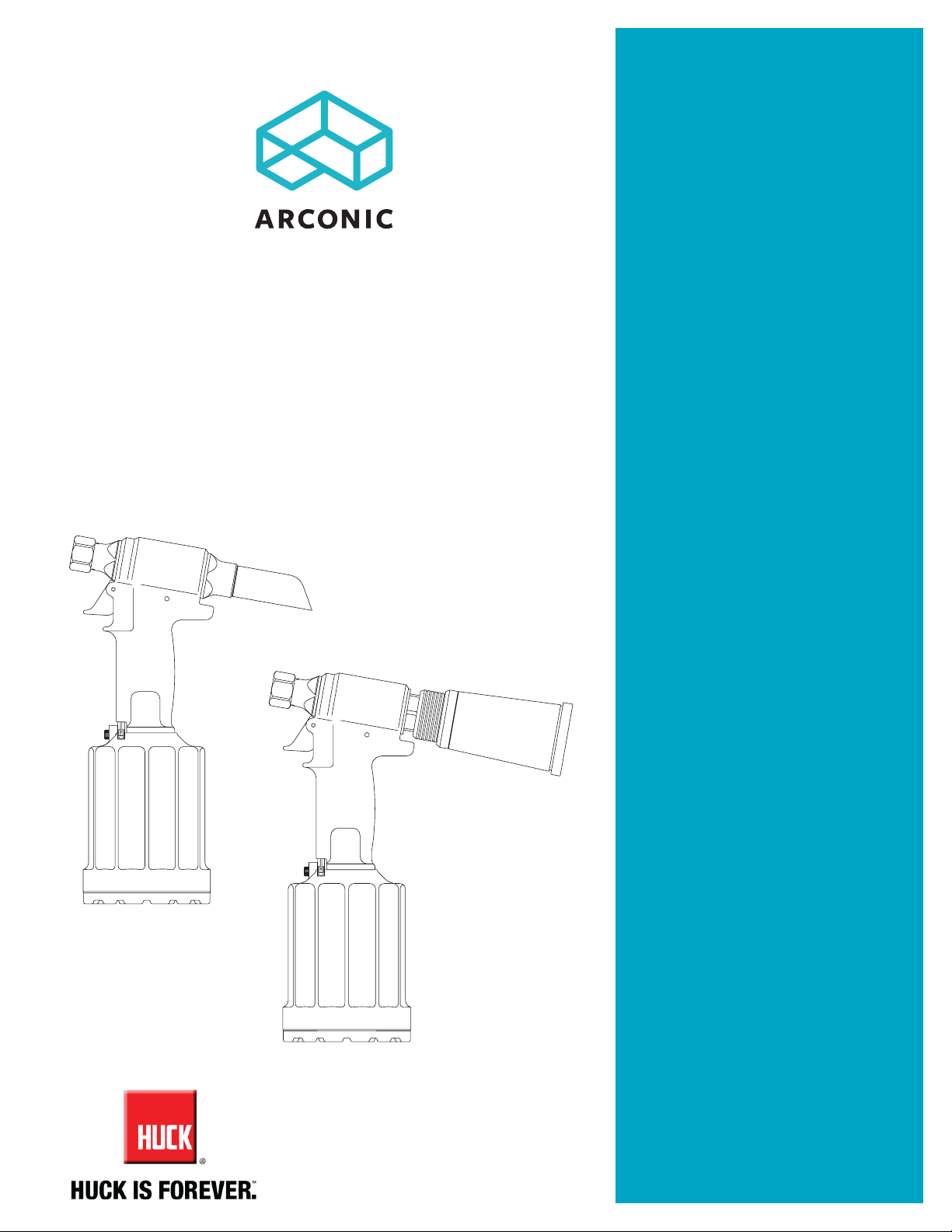
Instruction Manual
2024 series
Pneudraulic Installation Tool
Patent Pending
Specifications
4-6
Principle of Operation
7
Preparation for Use
7
Operating Instructions
8
Maintenance
8
Disassembly Instructions
9-10
Assembly Instructions
11-12
November 22, 2016
HK1077
Fill and Bleed
Measuring Tool Stroke
Components Drawings
15-17
Troubleshooting
Kits and Accessories
Makers of Huck®, Marson®, Recoil
Brand Fasteners, Tools & Accessories
®
13
14
18
18
Page 2
2024 series Pneudraulic Installation Tool (HK1077)
2
Page 3
Safety Instructions
GLOSSARY OF TERMS AND SYMBOLS:
- Product complies with requirements set forth by the
relevant European directives.
- Read manual prior to using this equipment.
- Eye protection is required while using this
equipment.
- Hearing protection is required while using this
equipment.
Notes: are reminders of required procedures.
Bold, Italic type, and underline: emphasize a specific
instruction.
WARNINGS: Must be understood to avoid
severe personal injury.
CAUTIONS: Show conditions that will damage
equipment or structure.
I. GENERAL SAFETY RULES:
1. A half hour long hands-on training session with qualified personnel is
recommended before using Huck equipment.
2. Huck equipment must be maintained in a safe working condition at all times.
Tools and hoses should be inspected at the beginning of each shift/day for
damage or wear. Any repair should be done by a qualified repairman trained on
Huck procedures.
3. For multiple hazards, read and understand the safety instructions before
installing, operating, repairing, maintaining, changing accessories on, or
working near the assembly power tool. Failure to do so can result in serious
bodily injury.
4. Only qualified and trained operators should install, adjust or use the assembly
power tool.
5. Do not modify this assembly power tool. This can reduce effectiveness of
safety measures and increase operator risk.
6. Do not discard safety instructions; give them to the operator.
7. Do not use assembly power tool if it has been damaged.
8. Tools shall be inspected periodically to verify all ratings and markings required,
and listed in the manual, are legibly marked on the tool. The employer/operator
shall contact the manufacturer to obtain replacement marking labels when
necessary. Refer to assembly drawing and parts list for replacement.
9. Tool is only to be used as stated in this manual. Any other use is prohibited.
10. Read MSDS Specifications before servicing the tool. MSDS specifications are
available from the product manufacturer or your Huck representative.
11. Only genuine Huck parts shall be used for replacements or spares. Use of any
other parts can result in tooling damage or personal injury.
12. Never remove any safety guards or pintail deflectors.
13. Never install a fastener in free air. Personal injury from fastener ejecting may
occur.
14. Where applicable, always clear spent pintail out of nose assembly before
installing the next fastener.
15. Check clearance between trigger and work piece to ensure there is no pinch
point when tool is activated. Remote triggers are available for hydraulic
tooling if pinch point is unavoidable.
16. Do not abuse tool by dropping or using it as a hammer. Never use hydraulic or
air lines as a handle or to bend or pry the tool. Reasonable care of installation
tools by operators is an important factor in maintaining tool efficiency,
eliminating downtime, and preventing an accident which may cause severe
personal injury.
17. Never place hands between nose assembly and work piece. Keep hands clear
from front of tool.
18. Tools with ejector rods should never be cycled with out nose assembly
installed.
19. When two piece lock bolts are being used always make sure the collar
orientation is correct. See fastener data sheet for correct positioning.
II. PROJECTILE HAZARDS:
1. Risk of whipping compressed air hose if tool is pneudraulic or pneumatic.
2. Disconnect the assembly power tool from energy source when changing
inserted tools or accessories.
3. Be aware that failure of the workpiece, accessories, or the inserted tool itself
can generate high velocity projectiles.
4. Always wear impact resistant eye protection during tool operation. The grade
of protection required should be assessed for each use.
5. The risk of others should also be assessed at this time.
6. Ensure that the workpiece is securely fixed.
7. Check that the means of protection from ejection of fastener or pintail is in
place and operative.
3
2024 series Pneudraulic Installation Tool (HK1077)
8. There is possibility of forcible ejection of pintails or spent mandrels from front
of tool.
III. OPERATING HAZARDS:
1. Use of tool can expose the operator’s hands to hazards including: crushing,
impacts, cuts, abrasions and heat. Wear suitable gloves to protect hands.
2. Operators and maintenance personnel shall be physically able to handle the
bulk, weight and power of the tool.
3. Hold the tool correctly and be ready to counteract normal or sudden
movements with both hands available.
4. Maintain a balanced body position and secure footing.
5. Release trigger or stop start device in case of interruption of energy supply.
6. Use only fluids and lubricants recommended by the manufacturer.
7. Avoid unsuitable postures, as it is likely for these not to allow counteracting of
normal or unexpected tool movement.
8. If the assembly power tool is fixed to a suspension device, make sure that
fixation is secure.
9. Beware of the risk of crushing or pinching if nose equipment is not fitted.
IV. REPETITIVE MOTION HAZARDS:
1. When using assembly power tool, the operator can experience discomfort in
the hands, arms, shoulders, neck or other parts of the body.
2. When using tool, the operator should adopt a comfortable posture while
maintaining a secure footing and avoid awkward or off balanced postures.
3. The operator should change posture during extended tasks to help avoid
discomfort and fatigue.
4. If the operator experiences symptoms such as persistent or recurring
discomfort, pain, throbbing, aching, tingling, numbness, burning sensations or
stiffness, these warnings should not be ignored. The operator should tell the
employer and consult a qualified health professional.
V. ACCESSORIES HAZARDS:
1. Disconnect tool from energy supply before changing inserted tool or
accessory.
2. Use only sizes and types of accessories and consumables that are
recommended. Do not use other types or sizes of accessories or consumables.
VI. WORKPLACE HAZARDS:
1. Be aware of slippery surfaces caused by use of the tool and of trip hazards
caused by the air line or hydraulic hose.
2. Proceed with caution while in unfamiliar surroundings; there could be hidden
hazards such as electricity or other utility lines.
3. The assembly power tool is not intended for use in potentially explosive
environments.
4. Tool is not insulated against contact with electrical power.
5. Ensure there are no electrical cables, gas pipes, etc., which can cause a hazard
if damaged by use of the tool.
VII. NOISE HAZARDS:
1. Exposure to high noise levels can cause permanent, disabling hearing loss
and other problems such as tinnitus, therefore risk assessment and the
implementation of proper controls is essential.
2. Appropriate controls to reduce the risk may include actions such as damping
materials to prevent workpiece from ‘ringing’.
3. Use hearing protection in accordance with employer’s instructions and as
required by occupational health and safety regulations.
4. Operate and maintain tool as recommended in the instruction handbook to
prevent an unnecessary increase in the noise level.
5. Select, maintain and replace the consumable / inserted tool as recommended
to prevent an unnecessary increase in noise.
6. If the power tool has a silencer, always ensure that it is in place and in good
working order when the tool is being operated.
VIII. VIBRATION HAZARDS:
1. Exposure to vibration can cause disabling damage to the nerves and blood
supply to the hands and arms.
2. Wear warm clothing when working in cold conditions and keep hands warm
and dry.
3. If numbness, tingling, pain or whitening of the skin in the fingers or hands, stop
using the tool, tell your employer and consult a physician.
4. Support the weight of the tool in a stand, tensioner or balancer in order to
have a lighter grip on the tool.
IX. PNEUMATIC / PNEUDRAULIC TOOL SAFETY INSTRUCTIONS:
1. Air under pressure can cause severe injury.
2. Always shut off air supply, drain hose of air pressure and disconnect tool
from air supply when not in use, before changing accessories or when making
repairs.
3. Never direct air at yourself or anyone else.
4. Whipping hoses can cause severe injury, always check for damaged or loose
hoses and fittings.
5. Cold air should be directed away from hands.
6. Whenever universal twist couplings (claw couplings) are used, lock pins shall
be installed and whip-check safety cables shall be used to safeguard against
possible hose to hose or hose to tool connection failure.
7. Do not exceed maximum air pressure stated on tool.
8. Never carry an air tool by the hose.
Page 4
2024 series Pneudraulic Installation Tool (HK1077)
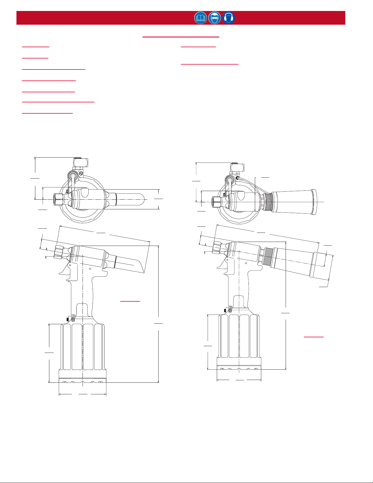
SpecificationS
STROKE: 0.850 in (2.16 cm)
WEIGHT: 5.5 lbs (2.5 kg)
MAX AIR PRESSURE: 90 psi (6.2 bar)
MAX FLOW RATE: 8.5 scfm (241 l/min)
POWER SOURCE: 90 psi (6.2 bar) maximum shop air
MAX OPERATING TEMP: 125° F (51.7° C)
PULL CAPACITY: 3993 lbs @ 90 psi (17.76 kN @ 6.2
bar); 3549 lbs @ 80 psi (15.79 kN @ 5.5 bar)
HOSE KITS: Use only genuine Huck Hose Kits rated @
10,000 psi (689.5 bar) working pressure.
HYDRAULIC FLUID: Hydraulic uid shall meet DEXRON®
III, DEXRON VI, MERCON®, Allison C-4 or equivalent
Automatic Transmission Fluid (ATF) specications. Fire-
resistant uid may be used if it is an ester-based uid
such as Quintolubric® HFD or equivalent. Water-based
uid shall NOT be used as serious damage to equipment
will occur.
DEXRON is a registered trademark of General Motors Corp.
MERCON is a registered trademark of Ford Motor Corp.
Quintolubric is a registered trademark of Quaker Chemical Corp.
3.9
(9.8)
1.1
(2.8)
0.9
(2.3)
10°
5.4
(13.7)
8.9
(2.6)
Models
2024 &
2024L
Ø
incheS
(cm)
(31.9)
1.8
(4.6)
12.5
3.9
(9.8)
1.1
(2.8)
0.9
(2.3)
10°
5.4
(13.7)
Ø
10.3
(26.2)
1.8
(4.6)
Models
2024V &
2024LV
Ø
(6.2)
12.5
(31.9)
incheS
(cm)
1.2
(3.2)
2.4
Ø
4.3
(11.0)
4.3
Ø
(11.0)
4
Page 5
2024 series Pneudraulic Installation Tool (HK1077)
principle of operation
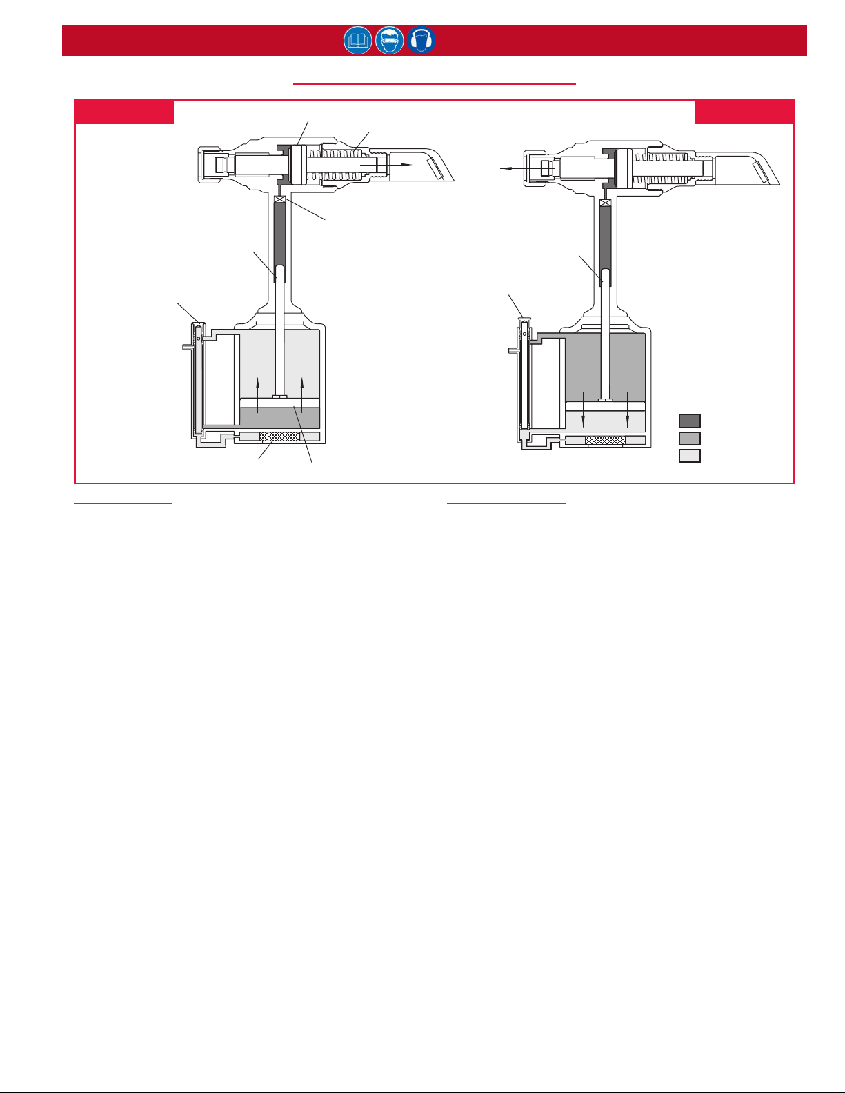
PULL STROKE
When tool is connected to the air supply, the air
pressure holds the throttle valve in the up (RETURN)
position; air pressure is directed to the top of the air
piston, keeping it down. When the trigger is pressed,
the throttle valve moves down to the PULL position, and
pressurized air is directed to the bottom of the air piston,
causing it to move upward (see above). The air above
the air piston is exhausted and directed through the
center of the throttle valve and out the bottom of the tool
(through the mufer).
As the hydraulic piston rod moves upward, a column
of pressurized uid is forced into head, which moves
the pull piston rearward. The attached nose assembly
moves with the pull piston to start fastener installation.
figure 1bfigure 1a
RETURN STROKE
When fastener installation is completed, the trigger is
released. Air pressure, with the assistance of a spring,
sends the throttle valve to the up (RETURN) position.
Pressurized air is re-directed to the top of the air piston
(see above), causing it and the hydraulic piston rod to
move downward.
The air from below the piston is exhausted through the
bottom of the tool. The piston and hydraulic piston rod
move downward, hydraulic pressure is reversed, and
the pull piston is returned forward. The damper valve
impedes oil ow at pinbreak helping prevent “Tool Kick”.
5
Page 6
2024 series Pneudraulic Installation Tool (HK1077)
preparation for uSe
WARNING:
As applicable, do not use without
deectors or pintail bottles.
If deectors are removed or damaged,
separated pintails may eject forcibly from
rear of tool. Unshielded eyes, especially,
may be permanently injured. Other severe
injuries can be caused by ying pintails.
If there is any chance of a projectile-like
ejection, always point rear of tool in a
safe direction, or be sure there is some
structure that will stop ejecting pintails.
The 2024 series of tools ship with a plug in the air inlet
connector. The connector has 1/4”-18 female pipe
threads to accept the air-hose tting. Huck recommends
quick-disconnect ttings and a 1/4” inside-diameter
air hose. The air supply should have a lter-regulator-
lubricator unit and access to 90 psi (6.2 bar), capable of
a ow rate of 8.5 CFM (241 l/m).
NOTE: Quick-disconnect ttings and air hoses are
not available for purchase from Huck International,
Inc. Huck includes an air hose (P/N 115436) to
facilitate immediate tool use.
1. Remove the shipping plug from air inlet connector
and add a few drops of an approved hydraulic uid.
2. Screw the quick-disconnect tting into the air inlet
connector.
CAUTION: Do not use TEFLON® tape
on pipe threads. Tape can shred and
break free into uid lines, resulting in
malfunctions. Threadmate® is available in a
4oz. tube from Huck (P/N 508517).
WARNING:
To avoid pinch points, be sure there is
adequate clearance for tool and operator’s
hands before proceeding. Tool moving
toward structure may crush hands or
ngers between tool and structure if
clearance is limited.
5. Disconnect the air hose from the tool, and remove
the retaining nut. Select the proper nose assembly
for the fastener being installed.
6. Screw the collet assembly (including the lock collar
and shim if applicable) onto the spindle and tighten
with a wrench.
7. Slide the anvil over the collet assembly and into the
counterbore. Slide the retaining nut over the anvil,
and screw the nut onto the head.
8. Connect the air hose to the tool and install fasteners
in a test plate of proper thickness with proper size
holes. Inspect the fasteners.
If the fasteners do not pass inspection, consult the
TroubleshooTing section to investigate possible causes.
NOTE: On older nose assemblies with lock collars, use
Loctite® 243™ on collet threads, because the 2024 pull
piston does not have staking holes. Refer to the nose
assembly drawings that shipped with nose assemblies.
3. Set the air pressure on the regulator to 90 psi
(6.2 bar), and connect the air hose to the air inlet
connector and the tool.
4. Press and release the trigger a few times to cycle
the tool.
Loctite is a registered trademark of Henkel Corporation, U.S.A.
Threadmate is a registered trademark of Parker Intangibles, LLC.
TEFLON is a registered trademark of E. I. du Pont de Nemours and
Company.
6
Page 7
2024 series Pneudraulic Installation Tool (HK1077)
operating inStructionS
Read all of these instructions in order to ensure the safe operation of this equipment.
This section details installing MAGNA-GRIP® and
Huck Blind Fasteners. Review all CAUTIONs and
WARNINGs prior to installing these fasteners. If the
tool malfunctions, consult the TroubleshooTing section
before attempting any repairs.
WARNINGS:
Inspect tools for damage and wear before
using. Do not use if damaged or worn;
serious personal injury may occur.
Pulling a pin (fastener) without a collar,
or with collar chamfer against workpiece,
may result in the pin becoming a highspeed projectile when the pin grooves are
stripped or the pintail breaks off. Serious
personal injury may occur to anyone in the
pin’s “ight path.” This includes pins that
ricochet.
Broken pintails eject from the deector
with speed and force. To reduce the risk of
serious personal injury, be sure the pintail
deector is properly attached and directed
away from all personnel. Replace damaged
pintail deectors.
NOTE: Reasonable care of tools by operators is
an important factor in maintaining efciency and
reducing downtime.
CAUTION: Make sure the tool is properly
re-assembled before use.
TO INSTALL A MAGNA-GRIP FASTENER:
1. Place a pin in the workpiece and place the collar
over the pin.
NOTE: If the collar has one tapered end, that end
must be out toward tool; not next to the sheet.
CAUTION: Remove excess gap from
between the sheets to permit proper
fastener installation and prevent jaw
damage. ALL jaw teeth must engage the
pintail to avoid damaging the teeth.
WARNINGS:
Wear approved eye and hearing protection.
Ensure adequate clearance for operator’s
hands before installing fasteners.
Be sure that the pintail deector is properly
attached to the tool and directed away from
all personnel.
Do not pull on a pin without placing a
fastener in a workpiece. Make sure that
the collar chamfer is out, towards the tool.
Pins eject with great velocity when pnntails
break off or teeth/grooves strip, which
could cause serious injury.
TO INSTALL A HUCK BLIND FASTENER:
CAUTION:
To avoid structural and tooI damage, be
sure there is sufcient clearance for the
nose assembly at full stroke.
Remove excess gap from between
the sheets to permit proper fastener
installation and prevent jaw damage. ALL
jaw teeth must engage the pintail to avoid
damaging the teeth.
1. Place a fastener in the workpiece or in the end of
the nose assembly.
NOTE: The tool or nose assembly must be
held against, and at a right angle (90°) to, the
workpiece.
2. Press and hold the trigger until the fastener is
installed and the pintail breaks.
3. Release the trigger; the tool will perform its
RETURN stroke.
The pressure is re-directed; the piston moves forward;
and the tool is pushed off the fastener and ready for the
next installation cycle.
For complete safety information, see page 4.
2. Hold the pin in the hole and push the nose
assembly onto the pin protruding through the collar
until the nose anvil touches the collar.
3. Press and hold the trigger until the collar is swaged
and the pintail breaks.
4. Release the trigger; the tool will perform its
RETURN stroke.
The pressure is re-directed; the piston moves forward;
and the tool is pushed off the fastener and ready for the
next installation cycle.
7
Page 8
2024 series Pneudraulic Installation Tool (HK1077)
Maintenance
GENERAL
The operating efciency of your tool is directly related
to the performance of the entire system. Regular
inspection and the immediate correction of minor
problems will keep the tool operating efciently,
and prevent downtime. A schedule of “preventive”
maintenance of the tool, nose assembly, hoses, trigger
and control cord, and POWERIG® will ensure your tool’s
proper operation and extend its life.
NOTE: Huck tools should be serviced only by
personnel who are thoroughly familiar with its
operation.
- Service the tool in a clean, well-lighted area. Take
special care to prevent contamination of pneumatic
and hydraulic systems.
- Have available all necessary hand tools (standard and
special), a brass drift and wood block, and a soft-jaw
vise. See KiTs & Accessories.
CAUTION: Replace all seals, wipers, and
rings when the tool is disassembled
for any reason, and at regular intervals,
depending on severity and duration of use.
- Carefully handle all parts. Before reassembly,
examine them for damage and wear.
- Disassemble and assemble tool components in a
straight line. Do NOT bend, cock, twist, or apply
undue force.
- Have the appropriate Spare Parts Service Kit
(2024KIT or 2024LVKIT) available when servicing
the tool; it includes important perishable parts. Other
components, as experience dictates, should also be
available. See KiTs & Accessories.
- Apply Loctite® 243 Threadlocker (Huck P/N 508567)
to gland threads. Apply Loctite® 271-05 (Huck P/N
503657) to nuts and locknut (P/N 505420); torque to
25–30 ft.-lbs.
- Smear LUBRIPLATE® 130-AA (Huck P/N 502723) or
SUPER-O-LUBE® (Huck P/N 505476) on rings and
mating parts to ease assembly.
- Apply Threadmate® (Huck P/N 508517) to pipe
threads and quick-disconnect ttings.
CAUTION: Do not use TEFLON® tape
on pipe threads. Tape can shred and
break free into uid lines, resulting in
malfunctions. Threadmate® is available in a
4oz. tube from Huck (P/N 508517).
DAILY
- Huck recommends using a lter-regulator-lubricator
unit. If one is not being used, uncouple the air
disconnects and add a few drops of hydraulic uid or
a light-weight oil to the air inlet of the tool.
NOTE: If the tool is in continuous use, add a few
drops of uid every 2–3 hours.
- Before connecting an air hose to the tool, clear the air
lines of dirt and water.
- Check all hoses and couplings for damage and air
leaks; tighten or replace if necessary.
- Check the tool and nose assembly for damage and
air or hydraulic leaks; tighten, repair, or replace if
necessary.
- Inspect the tool, hoses, and POWERIG during
operation to detect abnormal heating, leaks, or
vibration.
- Clean nose assemblies in mineral spirits to clear jaws
and rinse metal chips and dirt. For a more thorough
cleaning, disassemble the nose assembly. Use a
pointed “pick” to remove imbedded particles from the
pull grooves of the jaws.
Clean all parts of any assembly with UNITIZEDTM Jaws
in mineral spirits or isopropyl alcohol only; do not let
jaws come in contact with other solvents. Do not let
jaws soak; dry them immediately after cleaning. Huck
recommends drying other parts before re-assembling.
WEEKLY
- Disassemble, clean, and re-assemble nose assembly
in accordance with applicable instructions.
CAUTION: Damaged jaw teeth, or debris
packed between teeth, will result in
fastener not being installed or being
improperly installed.
- Check the tool and all connecting parts for damage
and uid/air leaks; tighten or replace if necessary.
Loctite is a registered trademark of Henkel Corporation, U.S.A.
LUBRIPLATE is a registered trademark of Fiske Brothers Rening
Co.
SUPER-O-LUBE is a registered trademark of Parker Hannin Corp.
Threadmate is a registered trademark of Parker Intangibles, LLC.
TEFLON is a registered trademark of E. I. du Pone de Nemours and
Company.
For supplementary information, see TroubleshooTing,
and the DisAssembly and Assembly procedures in this
manual.
8
Page 9
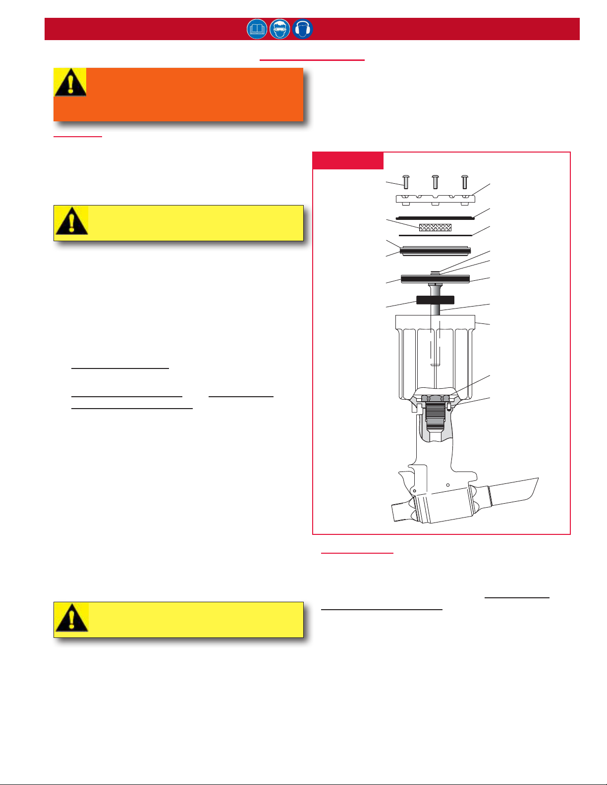
DiSaSSeMbly
WARNING: Disconnect the air hose
from the tool before performing any
maintenance. Serious personal injury could
result if the air hose is connected.
GENERAL
This procedure is for the complete disassembly of the
tool. Disassemble only those components necessary to
replace damaged O-rings, Quad-rings, Back-up rings,
and worn or damaged components. For component
identication, see Figures 2–5, 10, and 14.
CAUTION: Always use a soft-jaw vise to
avoid damaging the tool.
1. Disconnect the tool from the air source.
2. Unscrew the retaining nut and remove the nose
assembly. (Follow the instructions on the Nose
Assembly Data Sheet.)
3. Unscrew the bleed plug from top of the head/
handle. Turn over the tool (Figures 10 & 14) and
drain the uid into a container. (The tool can be
cycled to clear more completely.) Discard the uid.
4. Models 2024 & 2024L: Pull the pintail deector off
the end cap.
Models 2024V & 2024LV: See PinTAil boTTle/
VAcuum sysTem DisAssembly and Figures 5, 6, & 10.
5. Remove throttle arm pivot screw and lever guard,
and lift out throttle arm. Disconnect the ball end of
the cable assembly from it.
6. Secure the tool upside-down in a soft-jaw vise; use
a 1/8” hex key to remove button-head screws from
the mufer end cap. (Figure 2) Remove end cap
and gasket, and remove mufer from the end cap,
and spring from the throttle valve. (Figure 14)
7. Tap down the cylinder head with a soft mallet (to
take pressure off the ring), and remove the retaining
ring. (Figure 2)
8. Screw the button-head screws into cylinder head;
(Figure 2) carefully pry on screws to remove head.
Remove the O-ring.
CAUTION: Take care to not scratch the
piston, rod, or cylinder when removing.
9. Pull on locknut with vise-grips to remove the air
piston from cylinder. Remove the piston Quad-ring.
10. Remove bumper from the gland assembly. Unscrew
the gland assembly with a 1-3/8” socket wrench and
extension.
11. Remove retaining ring from gland, and then pull out
spacer and Polyseal. (Figure 2) Remove O-rings,
2024 series Pneudraulic Installation Tool (HK1077)
Quad-ring, and Back-up ring. Lift cylinder assembly
from the head/handle. (Figure 2)
12. Turn over the tool and drain the uid into a
container; discard the uid.
13. Remove throttle valve from air cylinder, and remove
the O-rings. (Figure 14)
figure 2
504127 Buon
Head Screw (3)
115554-1 Muffler
125747
Cylinder Head
500871 Cylinder
Head O-ring
501458 Quad Ring
116408 Bumper
HEAD/HANDLE
This procedure is applicable to models 2024 and 2024L.
For component identication, see Figures 3, 4, and 14.
For models 2024V and 2024LV, see PinTAil boTTle/
VAcuum sysTem DisAssembly.
1. Unscrew end cap; remove spring, spacer, and wiper
seal. (Figure 3)
2. Thread the Polyseal Insertion Tool into the rear of
the head/handle. NOTE: See Figure 3 for tool-
specic part numbers.
128792 Muffler
End Cap
126941-4 Gasket
507445 Retaining
Ring
505420 Locknut
506493 Washer
125744 Air Piston
125743 Piston
Rod
125733 Cylinder
(Figure 14)
Assy.
125742 Gland
(Figure 14)
Assy.
Timing Pin
9
Page 10
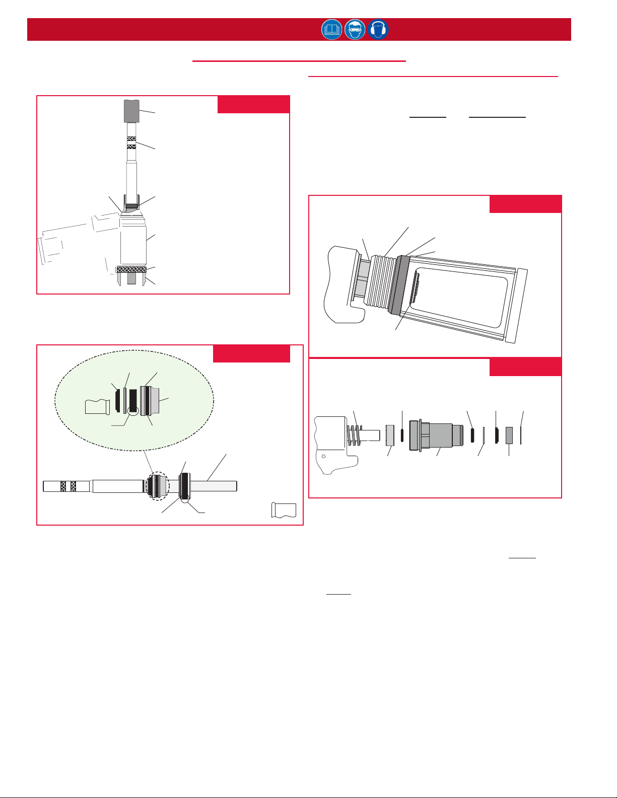
2024 series Pneudraulic Installation Tool (HK1077)
DiSaSSeMbly (continueD)
3. Slide the spacer onto the piston. Thread the Piston
Assembly Tool onto the piston. (Figure 3)
figure 3
123761 Adapter
PRESS
Piston Assembly Tool
123111-2 (2024)
123111-4 (2024L)
123112-4 (2024LV, 2024V)
Spacer
123112-2 (2024)
123112-3 (2024L, 2024LV, 2024V)
Handle Assembly
127748 (2024, 2024L)
128132 (2024LV, 2024V)
Polyseal Inseron Tool
121694-2024 (all models)
SUPPORT / STAND-OFF
4. Push the piston and front gland assemblies out
the back of the head/handle; allow clearance, with
stand-off, as the piston leaves the tool. (Figure 4)
122432
Gland Cap
505817
Wiper Seal *
505818
Polyseal *
Note orientaon of Wiper
Seal and Polyseals.
501110
Back-up Ring
123757
Front Gland
500816 O-ring
127749
Washer
figure 4
Piston Assembly
127743 (2024)
127744 (2024L)
127744-2 (2024V)
127744-1 (2024LV)
PINTAIL BOTTLE/VACUUM SYSTEM DISASSEMBLY
This procedure is applicable to models 2024V and
2024LV only; it should be used in conjunction with
the previous sections, generAl and heAD/hAnDle. For
component identication, see Figures 5, 6, and 15.
1. Reach through the window of pintail bottle and
remove retaining ring and washer. (Figure 5)
2. Remove pintail bottle, and then disconnect the tube
from the tubing connector. (Figure 15)
125862
End Cap
501007 Retaining Ring
and 506628 Washer
508187
Spring
500780
O-ring
125866
Spacer
figure 5
128044 Tubing & Slide Assembly
123784 Adapter
123772 Pintail Bole
figure 6
125862
End Cap
500809
O-ring
507351
Wiper
Seal
125865
Washer
502317
Retaining
Ring
125864
Wiper Housing
502827
Retaining Ring
508188 Polyseal *
(note orientaon)
5. Un-thread the Piston Assembly Tool and remove
spacer from the piston. Re-thread the Piston
Assembly Tool onto the piston, then slide the front
gland assembly off the piston. (Figure 4)
6. Remove the Piston Assembly Tool from the piston,
and remove the Polyseal Insertion Tool from the
rear of the head/handle.
7. Remove retaining ring, washer, and Polyseal from
the piston.
NOTE: Inspect the hydraulic piston for wear,
scoring, and damage; replace if necessary.
8. Unscrew the adapter. (Figure 14) Inspect all seals
and parts.
9. If trigger cable assembly is damaged, remove it by
driving out pin with a punch. Remove dowel pin to
disconnect the cable from the the trigger.
3. Remove the adapter and the Tubing & Slide
Assembly. Then remove the end cap and spring.
(Figure 6)
4. Remove the spacer and O-ring from the spring
side of the end cap. Remove retaining ring, wiper
housing, wiper seal, washer, and O-ring from the
bottle side of the end cap.
5. Remove O-rings from inside the adapter and Tubing
and Slide Assembly. (Figure 15)
10
Page 11
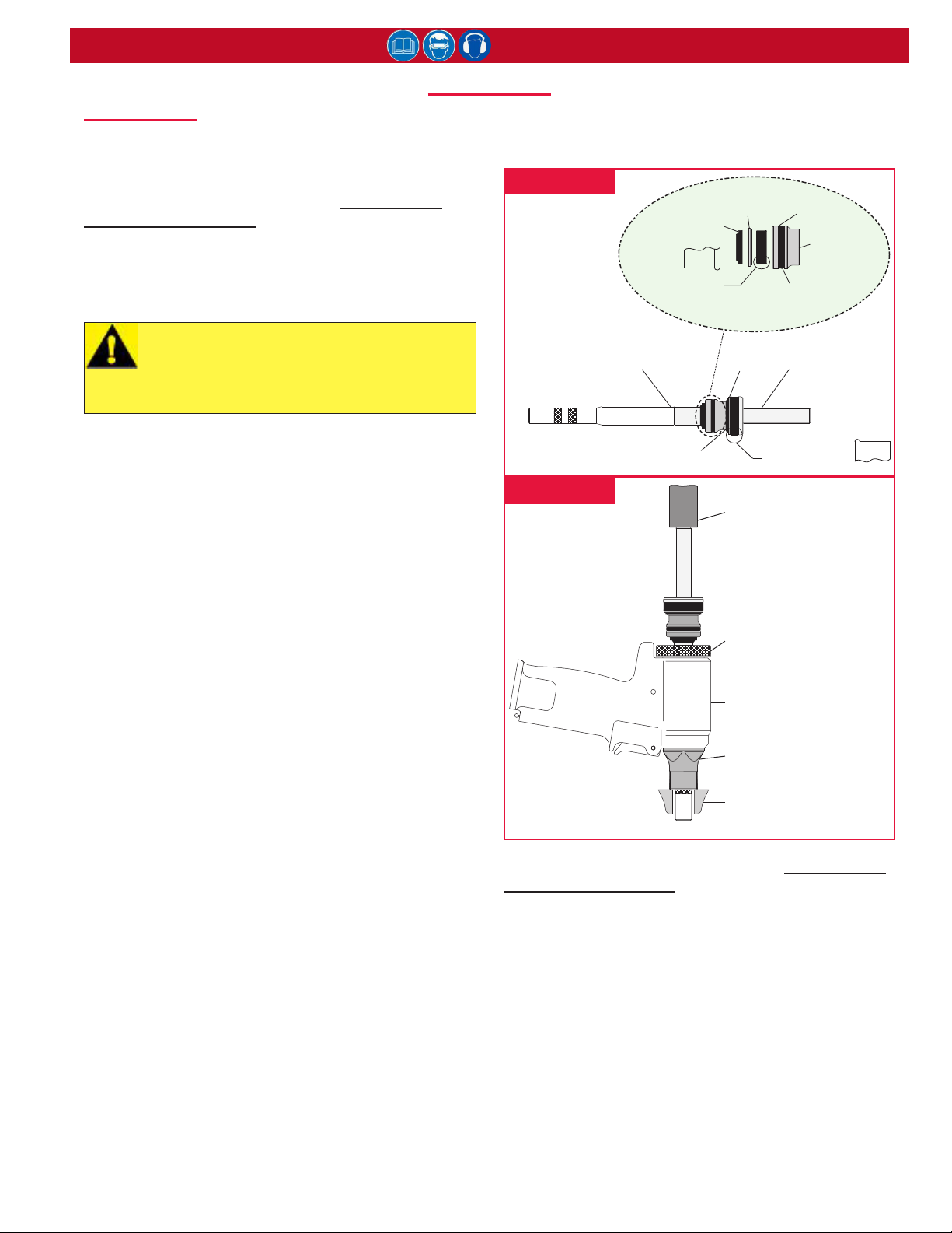
aSSeMbly
HEAD/HANDLE
This procedure is for the assembly of the head/handle
of models 2024 & 2024L. For component identication,
see Figures 7, 8, 14, and 15.
For models 2024V and 2024LV, see PinTAil boTTle/
VAcuum sysTem Assembly.
Prior to re-assembling the tool:
• Clean components with mineral spirits or a similar
solvent. Inspect for wear/damage and replace as
necessary.
CAUTION: Always replace all seals, wipers
and rings of disassembled components;
these parts wear out over time.
Replacement minimizes problems.
2024 series Pneudraulic Installation Tool (HK1077)
10. Slide spacer and spring into end cap, and then
thread the end cap assembly into the rear of the
head. (Figure 15)
figure 7
Wiper Seal
505818 Polyseal
(note orientaon)
Piston Assembly Tool
123111-2 (2024)
123111-4 (2024L)
123112-4 (2024LV, 2024V)
505817
122432
Gland Cap
127749
Washer
501110
Back-up Ring
123757
Front Gland
500816
O-ring
Piston Assembly
127743 (2024)
127744 (2024L)
127744-2 (2024V)
127744-1 (2024LV)
• Use the O-rings, Quad-rings, and Back-up rings from
Huck Service Parts Kits (P/N 2024KIT or 2024VKIT).
When assembling the tool, take care not to damage
O-rings, Quad-rings, Back-up rings.
Smear LUBRIPLATE® 130-AA (Huck P/N 502723) or
SUPER-O-LUBE® (Huck P/N 505476) on rings and
mating parts to ease assembly.
To re-assemble the tool:
1. If removed, position cable assembly in trigger slot
and slide dowel pin through the holes in trigger-andcable assembly. Position the assembled trigger in
the handle and drive pin through the holes in the
handle and trigger. (Figure 14)
2. Screw nose adapter into head; tighten.
3. Thread the Polyseal Insertion Tool (P/N 121694-
2024) into the head. (Figure 8)
4. Assemble piston, Polyseal, and retaining ring. (Note
the orientation of the Polyseal in Figure 7.)
5. Assemble front gland, O-ring, Back-up ring,
Polyseal, and gland cap. (Note the orientation of the
Polyseal in Figure 7.)
6. Thread the Piston Assembly Tool (see P/Ns in
gures) onto piston. Slide the complete gland
assembly and wiper seal onto piston.
7. Use a press to gently install the assembled
components through the rear of the tool. (Figure 8)
8. Remove the Piston Assembly Tool and the Polyseal
Insertion Tool.
9. Install rear wiper seal into end cap. (Figure 14)
502827
Retaining Ring
508188 Polyseal
(note orientaon)
figure 8
PRESS
Polyseal Inseron Tool
121694-2024 (all models)
Handle Assembly
127748 (2024, 2024L)
128132 (2024LV, 2024V)
123761 Adapter
SUPPORT / STAND-OFF
NOTE: Models 2024V and 2024LV, see PinTAil boTTle/
VAcuum sysTem Assembly and Figures 5, 6, and 10.
11
Page 12

2024 series Pneudraulic Installation Tool (HK1077)
aSSeMbly (continueD)
GENERAL
For component identication, see Figures 2, 7, and 13.
CAUTION: Always use a soft-jaw vise to
avoid damaging the tool.
1. Secure head/handle upside-down in a soft-jaw vise.
(Figure 2) Place the inverted cylinder assembly on
the base of the handle. (The timing pin maintains
orientation.)
2. Assemble gland assembly with new seals. (Note
the orientation of the Polyseal in Figure 7.) Apply
Loctite® 243™ to the threads of the gland assembly.
Screw the gland assembly into the handle/head.
Use a 1-3/8” socket wrench to tighten and torque to
36–66 ft.-lbs.
3. Push bumper rmly over the gland.
NOTE: The side of the bumper with two slots
must face the bottom of the tool.
4. Install Quad-ring onto air piston.
5. Clean the piston rod threads and apply Loctite®
243™. Press the assembled air piston/rod into the
cylinder just enough to allow installation of the
cylinder head.
6. Install O-ring on the cylinder head and then push
the cylinder head squarely into the cylinder, taking
care not to damage O-ring. Install the retaining ring;
align the screw holes with the mufer end cap.
7. Position mufer in center of cylinder head. (Figure
2) Position gasket on the cylinder. (Note the
orientation of the Polyseal in Figure 7.)
8. Carefully position bottom plate on the cylinder.
NOTE: Make sure the mufer is properly
positioned in the recess of the bottom plate.
(Figures 2 & 14)
9. Secure the bottom plate with three button-head
screws using a 1/8” hex key. (Figure 2)
10. Install O-rings on throttle valve. (Figure 14)
11. Place the tool upright on a level surface. Drop
spring into the throttle valve bore in cylinder, and
push the throttle valve into the cylinder.
12. Place the ball end of throttle cable into the end of
throttle arm, then slide the throttle arm into the slot
on the cylinder. (Figure 14)
13. Snap lever guard in place, and install pivot screw in
the cylinder to retain throttle arm.
14. Models 2024 & 2024L: Push pintail deector onto
end cap.
Models 2024V & 2024LV: see PinTAil boTTle/
VAcuum sysTem Assembly and Figures 5, 6, and 10.
The tool is now assembled and must be lled with
hydraulic uid prior to use. See the Fill AnD bleeD
section. NOTE: Install the bleed plug and O-ring
assembly after that process.
PINTAIL BOTTLE/VACUUM SYSTEM ASSEMBLY
This procedure is applicable to models 2024V and
2024LV only; it should be used in conjunction with
the previous sections, generAl and heAD/hAnDle. For
component identication, see Figures 5, 6, and 15.
1. Assemble adapter and Tubing & Slide Assembly
and new O-rings.
2. From the bottle side of end cap, install O-ring,
washer, wiper seal, wiper housing, and retaining
ring as shown in Figure 6.
3. From the tool side of the end cap, install O-ring,
spacer, and spring. (Figure 6) Screw the entire
assembly into the head; tighten.
4. Assemble the Tubing & Slide Assembly and O-rings;
slide the complete assembly onto end cap, and
push the tube into connector. (Figure 15)
5. Position adapter and pintail bottle on end cap.
(Figures 5 & 15)
6. Reach through the window of the pintail bottle and
install the washer and retaining ring as shown in
Figure 5.
LUBRIPLATE is a registered trademark of Fiske Brothers Rening Co.
SUPER-O-LUBE is a registered trademark of Parker Hannin Corp.
Loctite is a registered trademark of Henkel Corporation, U.S.A.
12
Page 13
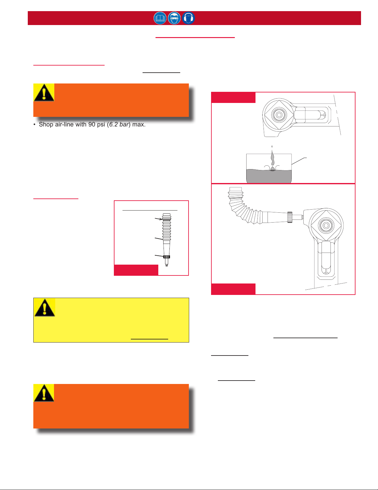
fill anD bleeD
This section documents the “bleed-&-ll” procedure. For
component identication, see Figures 9–11.
REQUIRED EQUIPMENT
• DEXRON® III or equivalent ATF (See sPeciFicATions
for more information.)
WARNING: Avoid contact with hydraulic
uid. Hydraulic uid must be disposed of
in accordance with local regulations. See
MSDS for hydraulic uid shipped with tool.
• Shop air-line with 90 psi (6.2 bar) max.
• Air regulator
• Fill Bottle Assy (P/N 120337, supplied with tool)
• Large at-blade screwdriver
• Stall Nut (P/N 124090 or 125340, optional)
• Nose assembly
• Fasteners (optional)
PREPARATION
• Install air regulator in
the air-line and set the
pressure to 20–40 psi
(1.4–2.8 bar).
• Add an approved hydraulic
uid to the ll point of the
ll bottle.
120337 Fill Bole Assy
Fill Point
120336
Fill Bole
120004
Cap
2024 series Pneudraulic Installation Tool (HK1077)
right-angle (90°) to the tool. (Figure 11) Air bubbles
will accumulate at top of the bottle.
5. When air bubbles stop accumulating at top of the
bottle, stop cycling the tool. When the trigger is
released, the pull piston returns to the idle position
(full-forward).
figure 10
CONTAINER
(Discard fluid)
To bleed and ll the tool:
1. Lay the tool on its side
with the ll port facing up and remove bleed plug
from the ll port.
CAUTION: All uid must be purged from
the tool before relling. The tool stroke will
be diminished if the uid is aerated.
For optimal performance, rell with a uid
that is recommended in sPeciFicATions.
2. Connect the tool to shop air-line. If uid is present,
hold the tool over a suitable container with ll port
facing into container. Cycle the tool several times to
drain old uid, air, and foam. (Figure 10)
WARNING: Air pressure must be set at
20–40 psi (1.4–2.8 bar) to prevent possible
injury from high-pressure spray.
If bleed plug (55) is removed, the ll bottle
must be in place before cycling the tool.
3. Screw the ll bottle into the ll port. (Figure 11)
4. Stand the tool upright on a bench. Trigger the tool
slowly (20–30 cycles), and bend the ll bottle at a
figure 9
figure 11
6. Disconnect the tool from the air-line. Lay the tool on
its side and remove the ll bottle. Top off the uid in
the ll port, and install and tighten the bleed plug.
7. Connect the air-line to the tool and measure the
stroke as described in meAsuring Tool sTroKe.
If the stroke is less than the length specied in
sPeciFicATions, remove the bleed plug and add uid.
Re-insert the bleed plug and re-measure the stroke.
8. Increase the air pressure to the the maximum listed
in sPeciFicATions. Install two fasteners to check the
function and installation in a single stroke, or cycle
the tool with a stall nut fully threaded onto the piston
to load up the tool. Measure the stroke again. If
necessary, remove the plug and add uid. Re-insert
the plug, and cycle and measure again. Repeat this
process until the stroke meets the recommended
minimal length.
DEXRON is a registered trademark of General Motors Corp.
13
Page 14
2024 series Pneudraulic Installation Tool (HK1077)
MeaSuring tool Stroke
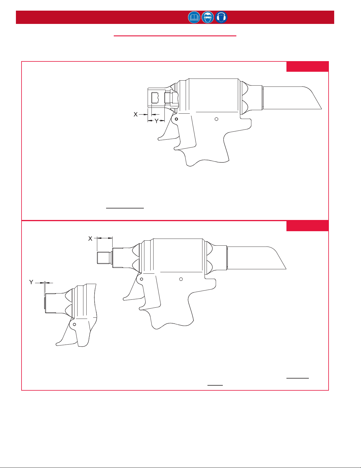
NOTE: Remove the Nose Assembly from the tool for both of the following procedures.
2024 & 2024V
1. Cycle the piston all the way forward and
measure X.
2. Cycle and hold the piston back and
measure Y.
Stroke = Y-X
If the stroke is less than 0.850 in (2.16 cm),
follow the steps at the end of the Fill AnD bleeD
procedure.
figure 12
figure 13
2024L & 202LV
1. Cycle the piston all the way forward
and measure X.
2. Cycle and hold the piston back and
measure Y.
Stroke = X-Y
If the stroke is less than 0.850 in (2.16 cm),
follow the steps at the end of the Fill AnD
bleeD procedure.
14
Page 15
2024 series Pneudraulic Installation Tool (HK1077)
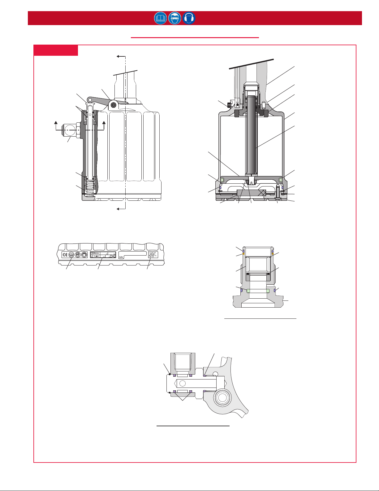
tool baSe (all MoDelS)
figure 14
125562-1
Throle Valve
507396
O-ring (2)
C C
507164
Swivel Assy
507396
O-ring
116272
Spring
125751
Throle Arm
A
125118
Pivot Screw
125744
Air Piston
125747
Cylinder
Head
500871
O-ring
A
115554-1
Muffler
506493
Washer
505420
Locknut
504127
Screw (3)
125742
Gland Assembly
(see below)
Timing Pin
116408
125733 **
Cylinder Assembly
125743
501458
507445
Retaining Ring
126941-4
Bumper
Piston Rod
Quad Ring
Gasket
Boom Plate128792
SECTION A-A
HUCK 2024
590350
CE Scker
** These sckers are at the base of Cylinder
Assembly 125733; they MUST be purchased and
placed as shown if they become damaged, lost, or
unreadable, or if the Cylinder Assembly is replaced.
590351
Max. Pressure
and Flow Scker
590347
HUCK Address
Scker
502274
Retaining
Ring
O-ring (2)
507167 SWIVEL ASSEMBLY
500785 O-ring
Back-up Ring
125741 Spacer
500778 O-ring
500779
SECTION C-C
501091
501075
Quad Ring
125742 GLAND ASSEMBLY
Tighten and torque to 36–66 .-lbs.
506876
Retaining Ring
507447 *
Polyseal
(note orientaon)
500787 O-ring
125740 Gland
Housing
15
Page 16
2024 series Pneudraulic Installation Tool (HK1077)
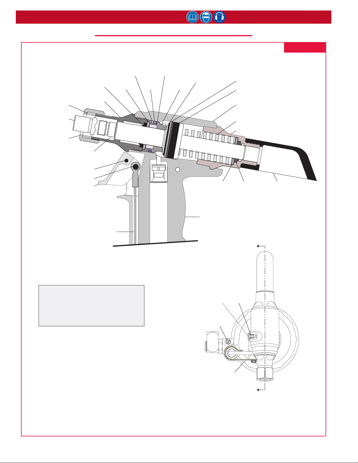
heaD/hanDle 2024 & 2024l
figure 14a
120588
Stop
127744 Piston
(2024L)
111795
Retaining Nut
127743 Piston
505817 *
Wiper Seal
123761
Adapter
(2024)
Trigger Pin500621
Dowel Pin505496
Trigger124333-2
Cable Assembly
Back-up Ring
116404-1
501110
122432
Gland Cap
505818 *
Polyseal
500816
O-ring
123757
Front
Gland
502827
Retaining Ring
507323
Spacer
127748 **
Handle
Assembly
Washer127749
Polyseal508188 *
590240-1 **
WARNING Scker
Spring508187
End Cap127742
507351 *
Wiper Seal
124210
Pintail Deflector
* Note orientaon of Wipers and Polyseals.
** WARNING scker (590240-1) MUST be
purchased and placed as shown when it
becomes damaged, lost, or unreadable, or
if Handle Assembly (127748) is replaced.
SECTION A-A
104293 Bleed
Plug Assembly
506576 Plug &
Gasket Assembly
126439 Guard
A
505438
O-ring
A
TOOL HEAD 2024 & 2024L
Top View
16
Page 17
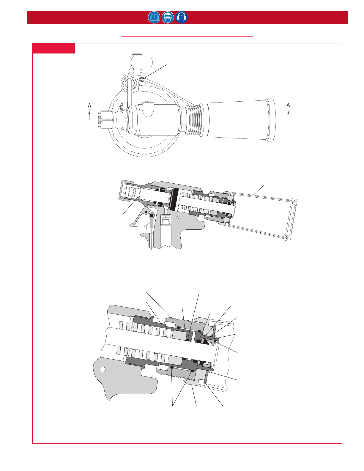
figure 15
2024 series Pneudraulic Installation Tool (HK1077)
heaD 2024V & 2024lV
506675 Tubing
Connector
123772 Pintail
Bole
Piston Assembly
127744-2 (2024V)
127744-1 (2024LV)
128044 Tubing
and Slide Assy
125862 End Cap
PARTIAL SECTION A-A
500780
O-ring
125866
Spacer
500809
O-ring
125865
Washer
507351
Wiper Seal
(Note orientaon.)
125864
Wiper Housing
502317
Retaining Ring
501007
Retaining
Ring
500790
O-ring (2)
17
123784
Adapter
506628
Washer
Page 18

2024 series Pneudraulic Installation Tool (HK1077)
troubleShooting
Always check the simplest possible cause (such as a loose or disconnected trigger line) of a malfunction rst. Then
proceed logically, eliminating other possible causes until the cause is discovered. Where possible, substitute known
good parts for suspected defective parts. Use this troubleshooting information to aid in locating and correcting
trouble.
1. Tool fails to operate when trigger is pressed.
a. Air-line not connected or air pressure too low.
b. Worn or damaged throttle valve O-rings.
c Broken throttle valve cable.
2. Tool does not complete fastener installation and
break pintail.
a. Air pressure too low.
b. Worn or damaged air piston Quad-ring.
c. Tool is low on hydraulic uid. See the Fill AnD
bleeD section.
d. Air in hydraulic system. See Fill AnD bleeD.
3. Pintail stripped and/or swaged collar not
ejected.
a. Check for broken or worn jaws in nose
assembly. See the Nose Assembly Data Sheet.
b Check for worn anvil. See the appropriate Nose
Assembly Data Sheet.
4. Hydraulic uid exhausts with air or leaks at
base of handle.
a. Worn or damaged gland assembly. Inspect
Polyseal and all rings. Replace if necessary.
5. Hydraulic uid leaks at rear of pull piston.
a. Worn or damaged hydraulic piston Polyseal.
Inspect Polyseal. Replace if necessary.
6. Hydraulic uid leaks at front of pull piston.
a. Worn or damaged part in front gland. Inspect
Polyseal and rings. Replace if necessary.
7. Pull piston will not return.
a. Throttle valve stuck; lubricate O-rings.
b. Throttle arm, cable, or trigger binding.
8. Air leaks at air cylinder head.
a. Worn or damaged O-ring. Replace if necessary.
kitS & acceSSorieS
Huck has created tool-specic Spare Parts Service Kits that contain various perishable parts. The types and
quantities of spare parts that should be available vary with the application and tools in use. Have the appropriate kit
accessible when using this tool and when performing maintenance on it. Huck Assembly Tool Kits have product-
specic tools that should be used when disassembling and assembling the tool.
Huck recommends having the following Accessories available when preparing, using, and performing maintenance
on this tool.
KITS
serVice KiTs - 2024KIT (2024 & 2024L)
- 2024LVKIT (2024LV & 2024V)
conVersion KiT (convert 2024L to 2024LV) - 126190
- Tubing and Slide Assembly - 124245
- Pintail Collection Bottle - 123772
- End Cap Assembly - 125863
- Piston Assembly - 125738-3
conVersion KiT (convert 2024 to 2024V) - 126432
- Tubing and Slide Assembly - 124245
- Pintail Collection Bottle - 123772
- Vacuum Attach Adapter - 123784
- End Cap Assembly - 125863
- Retaining Ring Ext - 501007
- Straight Connector - 506675
- Piston Assembly - 125738-2
- Flat Washer - 506628
Assembly Tool KiT - 123110-17 *
* The Model 2024L Kit P/N is 123110-18.
- Polyseal Insertion Tool - 121694-2024
- Piston Assembly Tool - 123111-2 (2024)
- 123111-4 (2024L)
- 123112-4 (2024LV, 2024V)
- Spacer - 123112-2 (2024)
- 123112-3 (2024V, L, & LV)
ACCESSORIES
Stall Nut
- 2024 & 2024V - 124090
- 2024L & 2024LV - 125340
Fill Bottle Assy (Fig. 9) - 120337
Damper Valve
Removal Tool - 123769
STANDARD TOOLS AVAILABLE FROM HUCK
- 1/8” hex key (P/N 502294), use on button-head screw
(P/N 504127)
18
Page 19

2024 series Pneudraulic Installation Tool (HK1077)
Limited Warranties
Tooling Warranty:
Huck warrants that tooling and other items (excluding
fasteners, and hereinafter referred as “other items”)
manufactured by Huck shall be free from defects in
workmanship and materials for a period of ninety (90) days
from the date of original purchase.
Warranty on “non standard or custom manufactured
products”:
With regard to non-standard products or custom manufactured
products to customer’s specifications, Huck warrants for a
period of ninety (90) days from the date of purchase that such
products shall meet Buyer’s specifications, be free of defects
in workmanship and materials. Such warranty shall not be
effective with respect to non-standard or custom products
manufactured using buyer-supplied molds, material, tooling and
fixtures that are not in good condition or repair and suitable for
their intended purpose.
THERE ARE NO WARRANTIES WHICH EXTEND BEYOND
THE DESCRIPTION ON THE FACE HEREOF. HUCK MAKES
NO OTHER WARRANTIES AND EXPRESSLY DISCLAIMS ANY
OTHER WARRANTIES, INCLUDING IMPLIED WARRANTIES
AS TO MERCHANTABILITY OR AS TO THE FITNESS OF THE
TOOLING, OTHER ITEMS, NONSTANDARD OR CUSTOM
MANUFACTURED PRODUCTS FOR ANY PARTICULAR
PURPOSE AND HUCK SHALL NOT BE LIABLE FOR ANY LOSS
OR DAMAGE, DIRECTLY OR INDIRECTLY, ARISING FROM THE
USE OF SUCH TOOLING, OTHER ITEMS, NONSTANDARD
OR CUSTOM MANUFACTURED PRODUCTS OR BREACH
OF WARRANTY OR FOR ANY CLAIM FOR INCIDENTAL OR
CONSEQUENTIAL DAMAGES.
Huck’s sole liability and Buyer’s exclusive remedy for any
breach of warranty shall be limited, at Huck’s option,
to replacement or repair, at FOB Huck’s plant, of Huck
manufactured tooling, other items, nonstandard or custom
products found to be defective in specifications, workmanship
and materials not otherwise the direct or indirect cause of
Buyer supplied molds, material, tooling or fixtures. Buyer shall
give Huck written notice of claims for defects within the ninety
(90) day warranty period for tooling, other items, nonstandard
or custom products described above and Huck shall inspect
products for which such claim is made.
Tooling, Part(s) and Other Items not manufactured by Huck:
HUCK MAKES NO WARRANTY WITH RESPECT TO THE
TOOLING, PART(S) OR OTHER ITEMS MANUFACTURED
BY THIRD PARTIES. HUCK EXPRESSLY DISCLAIMS ANY
WARRANTY EXPRESSED OR IMPLIED, AS TO THE CONDITION,
DESIGN, OPERATION, MERCHANTABILITY OR FITNESS
FOR USE OF ANY TOOL, PART(S), OR OTHER ITEMS
THEREOF NOT MANUFACTURED BY HUCK. HUCK SHALL
NOT BE LIABLE FOR ANY LOSS OR DAMAGE, DIRECTLY OR
INDIRECTLY, ARISING FROM THE USE OF SUCH TOOLING,
PART(S) OR OTHER ITEMS OR BREACH OF WARRANTY OR
FOR ANY CLAIM FOR INCIDENTAL OR CONSEQUENTIAL
DAMAGES.
The only warranties made with respect to such tool, part(s)
or other items thereof are those made by the manufacturer
thereof and Huck agrees to cooperate with Buyer in enforcing
such warranties when such action is necessary.
Huck shall not be liable for any loss or damage resulting from
delays or non-fulfillment of orders owing to strikes, fires,
accidents, transportation companies or for any reason or
reasons beyond the control of the Huck or its suppliers.
Huck Installation Equipment:
Huck International, Inc. reserves the right to make changes in
specifications and design and to discontinue models without
notice.
Huck Installation Equipment should be serviced by trained
service technicians only.
Always give the Serial Number of the equipment when
corresponding or ordering service parts.
Complete repair facilities are maintained by Huck International,
Inc. Please contact one of the offices listed below.
Eastern
One Corporate Drive Kingston, New York 12401-0250
Telephone (845) 331-7300 FAX (845) 334-7333
Outside USA and Canada
Contact your nearest Huck International Office, see back cover.
19
In addition to the above repair facilities, there are Authorized
Tool Service Centers (ATSC’s) located throughout the United
States. These service centers offer repair services, spare parts,
Service Parts Kits, Service Tools Kits and Nose Assemblies.
Please contact your Huck Representative or the nearest Huck
office listed on the back cover for the ATSC in your area.
Page 20

Arconic Inc. (NYSE: ARNC) creates breakthrough
products that shape industries. Working in close
partnership with our customers, we solve complex
engineering challenges to transform the way we fly,
drive, build and power.
Arconic Fastening Systems and Rings world-wide locations:
Through the ingenuity of our people and cuttingedge advanced manufacturing, we deliver these
products at a quality and efficiency that ensures
customer success and shareholder value.
AMERICAS
Kingston Operations
1 Corporate Drive
Kingston, NY 12401
800-278-4825
845-331-7300
FAX: 845-334-7333
Carson Operations
900 Watson Center Rd.
Carson, CA 90745
800-421-1459
310-830-8200
FAX: 310-830-1436
Waco Operations
PO Box 8117
8001 Imperial Drive
Waco, TX 76714-8117
800-388-4825
254-776-2000
FAX: 254-751-5259
Tucson Operations
3724 East Columbia
Tucson, AZ 85714
800-234-4825
520-747-9898
FAX: 520-748-2142
Acuña Operations
Hidalgo #120
Parque Industrial Amistad
26220 Acuña Coahuila
Mexico
FAX: 525-515-1776
TELEX: 1173530 LUKSME
EUROPE
Telford Operations
Unit C, Stafford Park 7
Telford, Shropshire
England TF3 3BQ
01952-290011
FAX: 0952-290459
Us Operations
BP4
Clos D’Asseville
95450 Us par Vigny
France
33-1-30-27-9500
FAX: 33-1-34-66-0600
FAR EAST
Melbourne Operations
11508 Centre Road
Clayton, Victoria
Australia 3168
03-764-5500
Toll Free: 008-335-030
FAX: 03-764-5510
Huck is Forever, For the Long Haul, The
Future of Fastening Technology, The Future of
Assembly Technology, The Future of Tooling
Technology, and Tools of Productivity are
service marks of Huck International. Huck
provides technical assistance regarding the use
and application of Huck fasteners and tooling.
NOTICE: The information contained in this
publication is only for general guidance
© 2016 Huck International, Inc.
1 Corporate Drive, Kingston, NY 12401 • Tel: 800-431-3091 • Fax: 845-334-7333
with regard to properties of the products
shown and/or the means for selecting such
products, and is not intended to create any
warranty, express, implied, or statutory;
all warranties are contained only in Huck’s
written quotations, acknowledgments, and/
or purchase orders. It is recommended that
the user secure specific, up-to-date data and
information regarding each application and/or
use of such products.
 Loading...