

Page 1
c
Huck International, Inc. 1999 HK 958 Rev. 06/05/01
U.S. patents Des. 369732; 369733; 371299, 5490311
INSTRUCTION MANUAL
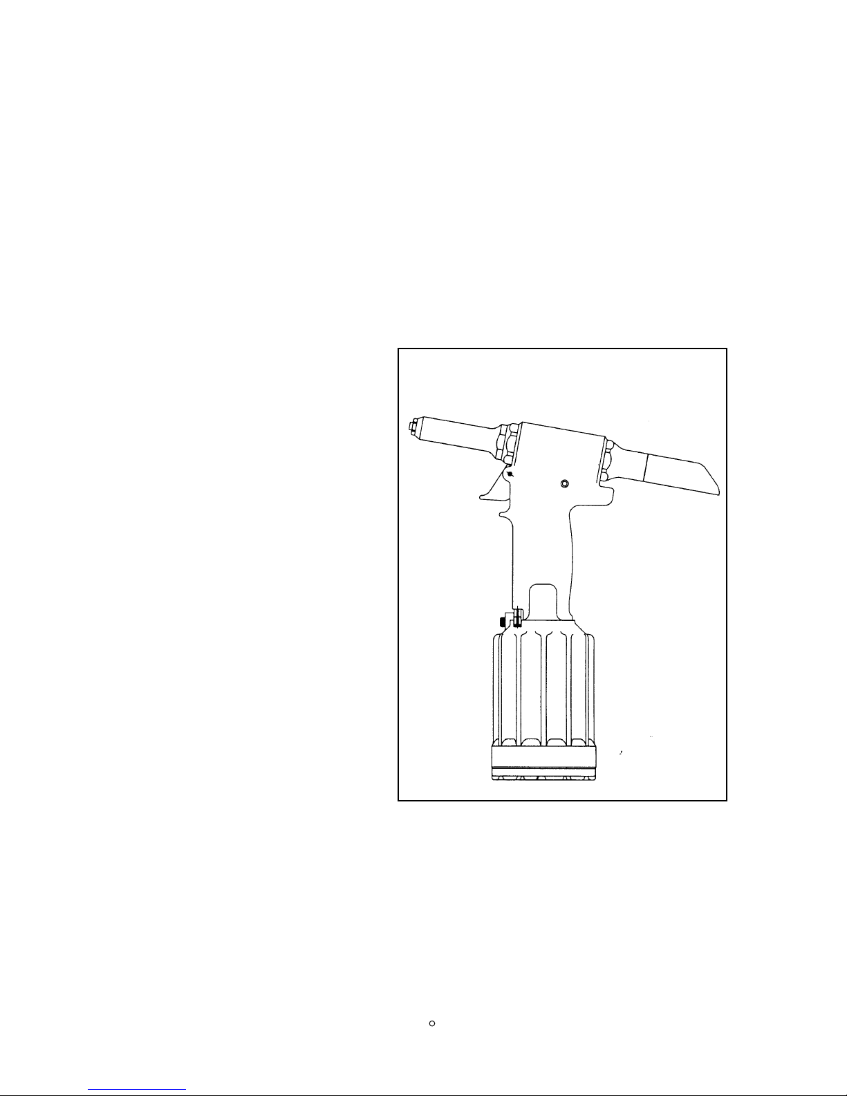
2015 ALL MODELS
PNEUDRAULIC I
NSTALLATION TOOL
HUCK FASTENERS
HUCK FASTENERS
HUCK FASTENERS
HUCK FASTENERS
HUCK FASTENERS
HUCK FASTENERS
HUCK FASTENERS
HUCK FASTENERS
Page 2

EU Declaration of Conformity
Manufacturer:
Huck International Inc., Installation Systems Division, 85 Grand Street, Kingston, NY, 12401,
USA
Description of Machinery:
Model number 201 family of fastener installation tools
Relevant provisions complied with:
Council Directive related to Machinery, (89/392/EEC), (91/368/EEC), (93/44/EEC),
(93/68/EEC)
European Representative:
Rob Pattenden, Huck International, Ltd. Unit C Stafford Park 7, Telford Shropshire TF3 3BQ,
England, United Kingdom
Authorized Signature/date:
I, the undersigned, do hereby declare that the equipment specified
above conforms to the above Directive(s) and Standard(s).
Signature:
Full Name: Renno Budziak
Position: Vice President of Engineering, Installation Systems Division
Place: Kingston, New York, USA
Date: November, 1995
2015 TOOLING HUCK FASTENERS
Page 3

2015 TOOLING HUCK FASTENERS
Huck Model 201 (family) Sound Level
SEL --- 75.7 dB (A)
peak value = 104.4 dB (C)
For an eight hour work day, installing 3000 typical Huck fasteners will result in an
equivalent noise level (Leq) of 65.9 dB (A).
To calculate equivalent noise level for other quantities of fasteners in an eight hour
period, use the formula:
Leq = SEL + 10 log (n/28,800)
where n = number of fasteners in eight hours.
Huck Model 201 (family) Vibration Level
For an eight hour work day, installing 3000 typical Huck fasteners will result in an
equivalent weighted RMS vibration level (Aeq) of 12.25rn/s
2
.
To calculate the equivalent vibration level for other quantities of fasteners in an eight
hour period, use the formula:
Equivalent Vibration Level, Aeq (rn/s
2
) = (n/480) x 1.96
where n = number of fasteners in eight hours, and 1.96 (m/s2) = Aeq for 60 seconds
Test data to support the above information is on file at Huck International, Inc. Kingston, N.Y. Vibration
measurements are frequency weighted in accordance with ISO 8041 (1990).
Page 4

2015 TOOLING HUCK FASTENERS
CONTENTS
Section Page
Summary of Safety Guidelines 1, 2, 3
Description 5
Specifications 5
2015 series Outline Dimensions 6, 7
Principle of Operation 8
Preparation for Use 9
Operating Instructions 10
Maintenance 10
Good Service Practices 10
Standard Tools 11
Preventive Maintenance 11
Tool Maintenance 11
Nose Assembly Maintenance 11
Filling and Bleeding/Measuring Stroke Procedure 12 - 15
Troubleshooting 16
Spare Parts and Service Kits 16
Disassembly 17 - 30
Assembly 19 - 32
Sub-assembly Part Numbers and Notes 33
Specifications for Standard Parts 34
Accessories: Tools, Components and Kit 35, 38
Service Kits, 2012KIT and 2012BKIT 36
Service Kit, 2012VKIT 37
Page 5

2015 TOOLING HUCK FASTENERS
ILLUSTRATIONS
Figure Page
1. 2015 series Outline Dimensions 6, 7
2. Main Components 8
3. Filling and Bleeding Procedure 12 - 15
3.5 Checking Tool Stroke with Stall-nut 14
3.6 Checking Tool Stroke without Stall-nut 15
4. 2015 Head/handle 19
5. Air Cylinder and Gland Assembly 20
5.1 Gland Assembly, 116134-1 20
6. Throttle Valve Sub-assembly and Related Components 21
7. Swivel Sub-assembly and Fill Plug Sub-assembly 22
8. 2015B Head/handle 23
9. 2015V Head/handle 24
10. 2015V Assembled Vacuum Attachment 25
11. Exploded View of Vacuum Attachment 26
12. Removing Piston and Front Gland 28
13. Installing Piston and Front Gland 29
14. Anvil Inserts used With Pintail Tube 35
15. 2015 with Suspension Spring 38
Page 6

An important notice:
Operator must read and understand any
WARNING and Caution stickers/labels
supplied with equipment before connecting
equipment to any primary power supply — as
applicable, the following sections each have
specific safety, and other, information:
• WARNINGS and CAUTIONS
• DESCRIPTION
• SPECIFICATIONS
• PRINCIPLE OF OPERATION
• PREPARATION FOR USE
• PREVENTIVE MAINTENANCE
• OPERATION AND TOOL HANDLING
As applicable, the disassembly and assembly
sections contain specific overhaul and safety
procedures.
Only persons who have read and understood all
applicable manuals or received training
approved by Huck International, Inc. will be
able to use Huck equipment with personal
safety and efficiency.
If you require additional information, contact
your local Huck representative or the nearest
office listed on the back cover.
SAFETY GLOSSARY
WARNINGS must be understood to avoid
severe personal injury.
Cautions show conditions that will damage
equipment and/or structure.
Notes are reminders of required procedures.
It
alic type and underlining strengthens a
specific instruction.
1
2015 TOOLING HUCK FASTENERS
WARNINGS
When operating Huck installation equipment
always wear approved eye protection.
Whenever within the working environment,
wear approved eye protection, with side
shields, to protect from anything that
breaks on the fastening system including:
Erupting fluid lines, flying fastener particles
or any other dirt/debris that could cause eye
injury. Where applicable, refer to ANSI
Z87.1 - 1989.
Disconnect primary power source before
doing maintenance on Huck equipment.
• For electrically operated POWERIG®
Hydraulic Units, unplug the power cord
from the socket. If there is no plug, turn
off the power at the disconnect switch.
Follow lockout/tagout procedures In
force by your employer.
• For equipment powered by compressed
air, disconnect the air hose before doing
any maintenance.
• For hydraulic tools, or other hydraulic
equipment, disconnect the hydraulic
hoses from the hydraulic unit before
doing any maintenance.
If any equipment shows signs of damage or
leakage, DO NOT
connect it to the primary
power supply (either electrical or
compressed air) - - and do not continue to
use equipment that deveiops erratic
symptoms. If equipment is damaged, or
there are other serious discrepancies,
affected equipment may rupture violently
- - parts may strike the operator, and/or
other personnel, and cause severe personal
injury. Ensure that ALL
air and/or
hydraulic hose and/or electrical
plugs/connectors are correctly connected
before switching on power supply to
equipment. If incorrectly connected, the
tool may respond erratically and cause
severe personal injury.
continued. . . 7-1-97
Page 7

Except where noted, these are WARNINGS
and involve possible serious personal
injury. There may be other WARNINGS,
Cautions and Notes in the manual that
must be checked before operating
installation tools:
1. Only Huck Installation Equipment should
be used to install Huck fasteners.
2. Only persons that have received training
approved by Huck International, Ltd.
should use Huck Installation Equipment.
3. The Manuals, Nose Assembly Data
Sheets, and WARNING stickers supplied
with the installation equipment should be
studied before connecting the equipment to
any primary power supply, in particular
the following sections require complete
understanding:
• WARNINGS and Cautions
• SPECIFICATIONS
• ELECTRICAL and/or AIR SUPPLY
• PRINCIPLE OF OPERATION
• PREPARATION FOR USE
• OPERATING INSTRUCTIONS
• MAINTENANCE
4. With hydraulic tooling, be sure that it is
suitable for use with the POWERIG®
Hydraulic Unit or Huck approved
handpump being used.
2
2015 TOOLING HUCK FASTENERS
5. Check that hydraulic unit or approved
hand pump PULL and RETURN
pressures have been adjusted to suit the
tool being used. Refer to the specific
instruction manual supplied with the
equipment.
6. Caution: Check that the nose assembly is
the correct type and size suitable for
installing the fastener being used.
7. Visually check ALL
pneumatic and
hydraulic hoses, electrical cables,
hydraulic units. hand pumps and hand
tools for any visible signs of damage and
leakage.
8. Do not connect any equipment to primary
power supplies. or attempt to use any
equipment that shows signs of damage or
leakage.
9. Be sure that ALL
air and hydraulic hoses
and electrical cords are correctly connected
before switching on power supply to
equipment
10.Disconnect primary power source before
doing ANY
maintenance on either
hydraulic unit or on equipment
connected to the unit.
2-18-9 7
Preparing to Safely Operate
Huck Fastener Installation Equipment
Using CE and General Safety Guidelines
Page 8

2015 TOOLING HUCK FASTENERS
3
Except where noted, these are WARNINGS
and involve possible serious personal
injury. There may be other WARNINGS,
Cautions and Notes in the manual that
must be observed when operating
the
equipment:
I. Approved eye protection (e.g. safety
glasses) must be worn by the operator.
2. When using fasteners in some types of
structure, the fracturing of the pintail
during installation may generate noise
levels above the first action level of the
Noise at Work Regulations and therefore
approved hearing protection must be worn.
3. NEVER
look directly at the front or rear
of the installation tool when it is in use.
4. NEVER use the nose assembly for a tool
handle. Do not grip the nose assembly
during fastener installation.
5. Keep hands/fingers clear of any moving
parts and away from holes in nose
assemblies.
6. DO NOT
pull on a pin (fastener) without a
collar. When there is only one collar
chamfer, it MUST
be out toward the tool
-- NOT against the workpiece. Fastener
will eject at high velocity when pintail
fractures and may cause serious injury.
7. DO NOT
pull on a fastener’s pintail
without first placing the fastener in a
workpiece. Fasteners installed “in
air” will eject at high velocity when the
pintail fractures and may cause serious
injury.
8. Keep fingers clear from the underside of
the head (blind side) and collar of the
fastener. Keep fingers from within the
joint.
9. Do not look directly at the head, or blind
side, of fasteners during the installation
cycle.
10.KEEP
HANDS CLEAR during the
installation cycle as the tool will pull and
straighten itself to the axis of the fastener.
Beware of hands being trapped against
any nearby structure.
11. NOTE:
The trigger on the tool is the
operator’s direct link to controling swaging
movement. Releasing the trigger at any
time during the installation cycle will
immediately put the tool into reverse.
12.Beware of fastener pintails which are
ejected, (sometimes forcibly), when pintail
breaks during the installation cycle. The
pintail deflector, bottle, or catcher must
always be in place on the tool - - direct
deflector away from people.
13.Do not continue to use any equipment that
develops any type of malfunction while
being used.
14.Do not drag hoses and electrical cables.
Avoid kinking hoses.
Safe Operation and Handling
of Huck Fastener Installation Equipment
Using CE and General Safety Guidelines
Page 9

4
2015 TOOLING HUCK FASTENERS
-------------------- S
ERVICE NOTES: ---------------------
Page 10

5
Pulling action of the pull piston is provided by
a pneumatic-hydraulic (pneudraulic)
intensifier system powered by 90-100 psi air
pressure. The air inlet is equipped with a
connector with 1/4-18 female pipe threads to
accept your air hose or quick connect fitting.
The piston return stroke is spring actuated.
SPECIFICATIONS
• Min. Stroke: .683
• Air Pressure: 90-100 psi
• Speed/Cycles: 30 per minute
• Air Consumption: 4.3 CFM
MODEL 2015 TOOL All Models HUCK FASTENERS
DESCRIPTION
The Model 2015 series tools are lightweight,
high speed production tools designed to
install 3/32 and 1/4 nail type blind fasteners.
An integral nose asembly increases
reliability and simplifies use of this tool.
The 2015V, with vacuum boost selector
switch ON, has two functions:
1. With tool in any position, vacuum holds
fastener firmly in nose assembly.
2. Vacuum expels broken pintail into pintail
collector.
• Weight of 2015: 4.9 lbs
• Weight of 2015B & 2015V: 5.2 lbs
• Min. Capacity: 2670 lbs @ 90 psi
Fasteners installed: Consult your Huck representative or available FASTENER SELECTION
CHARTS.
Hydraulic Fluid: Automatic Transmission Fluid, DEXRON Ill, or equivalent.
Page 11
2015 TOOLING HUCK FASTENERS
6
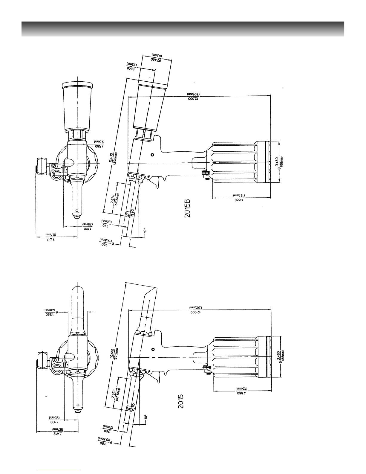
Figure 1 - 2015 and 2015B Outline Dimensions
Page 12
2015 TOOLING HUCK FASTENERS
7
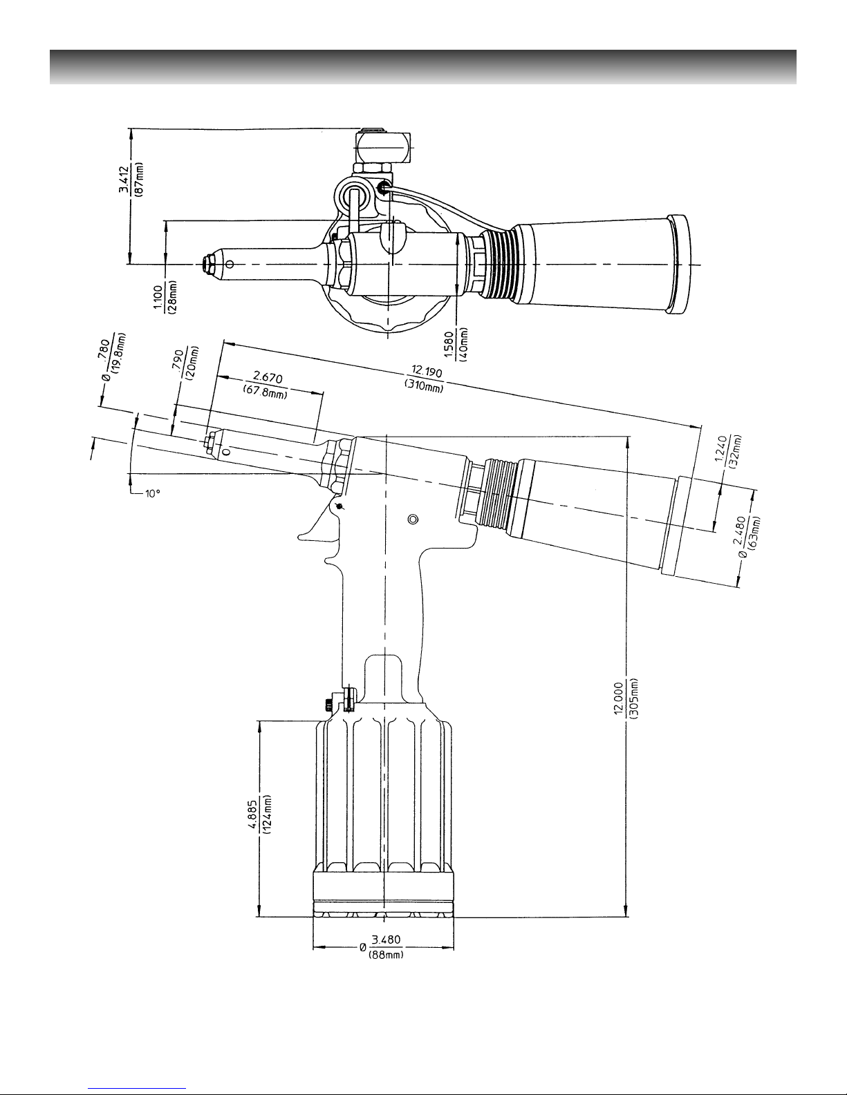
Figure 1A - 2015V Outline Dimensions
Page 13
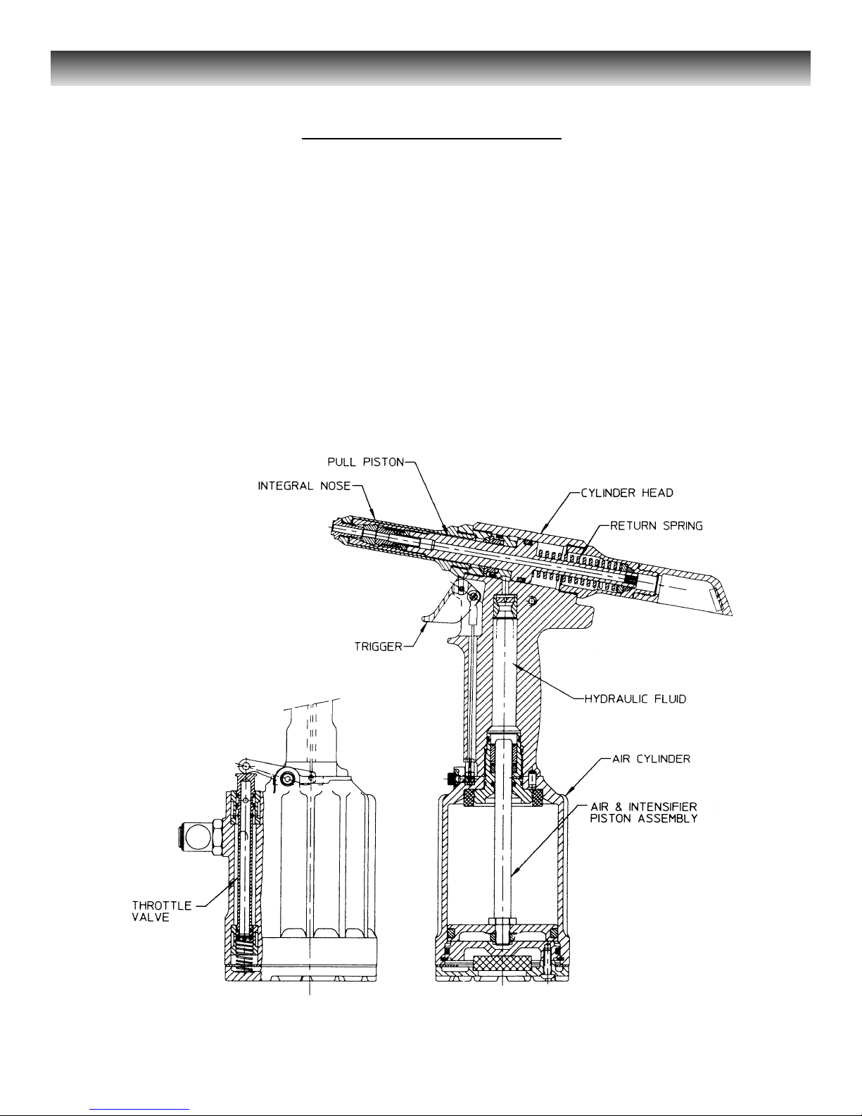
When tool is connected to proper air supply,
air pressure holds throttle valve in the up
position - - air pressure is directed to the top of piston
keeping it down. Depressing trigger moves throttle
valve to the down position - - air is
directed to the bottom of the piston moving it
upward, air from above piston is exhausted
downward thru the throttle valve and exits the
muffler at bottom of tool. Air piston
rod is a hydraulic piston. Pressurized
fluid is forced into the cylinder head moving
pull piston rearward. The nose, which
is connected to the pull piston, will install the
fastener during the rearward piston movement.
8
2015 TOOLING HUCK FASTENERS
When fastener installation is completed, and
upon trigger release, air pressure causes
throttle valve to return to its up position - - air
flow reverses. The air piston and rod move
down to their starting position, exhausting air
from below the piston through the muffler at
bottom of tool. As rod moves downward and
hydraulic pressure is released from pull piston,
a spring behind pull piston returns it to its
starting position.
Figure 2 - Main Components
PRINCIPLE OF OPERATION
Page 14

9
WARNING
As applicable, do not use without deflectors or pintail bottles.
If deflectors are removed or damaged,
separated pintails may eject forcibly from
rear of tool. Unshielded eyes, especially,
may be permanently injured. Other severe
injuries can be caused by flying pintails. If
there is any chance of a projectile-like
ejection, always point rear of tool in a safe
direction, or be sure there is some structure that will stop ejecting pintails.
W
ARNING
To avoid pinch points, be sure there is
adequate clearance for tool and operator’s
hands before proceeding. Tool moving
toward structure may crush hands or
fingers between tool and structure if
clearance is limited.
The 2015 is equipped with a plastic plug in
the air inlet connector. Connector has 1/4-18
female pipe threads to accept the hose fitting.
Quick connect fittings and 1/4 inch inside
diameter air hose are recommended. An air
supply of 90-100 psi, capable of 4.3 CFM,
must be available. Air supply should be
equipped with a filter-regulator-lubricator unit.
PREPARATION FOR USE
MODEL 2015 TOOL All Models HUCK FASTENERS
1. Remove plastic plug from air inlet
connector and drop in a few drops of
Automatic Transmission Fluid, DEXRON
Ill, or equivalent.
2. Screw quick-connect fitting into air inlet
connector.
3. Set air pressure on regulator to 90-100 psi.
4. Attach optional air hose, part number
115436 (supplied with tool), to air inlet
connector.
5. Connect air hose to tool.
6. Cycle tool a few times by depressing and
releasing trigger.
7. Disconnect air hose from tool.
8. Remove retaining nut.
9. Select correct nose assembly from the
available SELECTION CHARTS or speak
with your Huck representative.
NOTE:
Quick disconnect fittings and air hoses are not
available from Huck.
Page 15

2015 TOOLING HUCK FASTENERS
10
NOTE: 2015V is sold with the ribbed
vacuum control ON/OFF slide in the forward
or OFF position. See FIGURE 10 for slides
location which is shown in the ON (rear)
position. While tool is not being used, move
slide to the OFF (forward) position to prevent
unnecessary air loss.
Nail Type Blind Fastener Installation:
The fastener may be placed, either in the work
hole or, in the end of the nose assembly. In
either case, tool and nose assembly must be
held against work and at right angles to it.
Depress trigger and hold it depressed until
fastener is installed and pintail breaks.
Release trigger.
Warnings
Inspect tool for damage before each use.
Do not operate if damaged as severe
personal injury may occur.
Broken pintails eject from deflector with
speed and force - - be sure pintail deflector
is directed safely away from operator or other
personnel in the area. Ejecting pintails
striking anyone may cause serious personal
injury. For Models 2015B and 2015V,
pintail bottles must always be used. Replace
damaged pintail deflectors and bottles as
serious personal injury may occur from
pintails when using these defective parts.
Good Service Practice
Service Kits, 2015KIT and 20I5VKIT,
include perishable parts and should be on hand
at all times. Other components, as experience
dictates, should also bo kept for replacements.
AL
WAYS REPLACE O-RINGS AND
BACK-UP RINGS WHEN TOOL IS
DISASSEMBLED FOR ANY REASON.
The efficiency and life of any tool depends
upon proper maintenance and good service
practices. Tool should be serviced by
personnel who are thoroughly familiar with it
and how it operates.
A clean, well-lighted area should be available
for servicing the tool. Special care must be
taken to prevent contamination of pneumatic
and hydraulic systems. Proper hand tools and
soft materials to protect tools must be
available. Use only standard hand tools, brass
drift and wood block. Vise with soft jaws
should be available. Unsuitable hand tools
will cause installation tool damage.
All parts must be handled carefully and
examined for damage and/or wear.
Components should be disassembled and
assembled in a straight line without bending,
cocking or undue force. Disassembly and
assembly procedures outlined in this manual
should be followed. If Huck recommended
procedures are not followed, the tool may be
damaged.
Rub SLIC-TITE TEFLON* thread compound,
or equivalent, on pipe plug threads and quick
connect fitting.
CAUTION
: Do not use TEFLON tape on
pipe threads. Pipe threads may cause tape
to shred resulting in tool malfunction.
(SLIC-TITE is available in stick form, as
503237, from Huck.)
OPERATING INSTRUCTIONS
MAINTENANCE
Page 16

2015 TOOLING HUCK FASTENERS
Tool Maintenance
The 2015 series require a minimum amount of
maintenance. Regular inspection and
correction of minor problems will keep the
tool operating efficiently and prevent
downtime.
Using filter-regulator-lubricator unit is highly
recommended for safe and reliable tool
operation. If a filter-regulator-lubricator unit is
not being used in the air supply: (1) remove
hose fitting from air inlet connector and drop
in a few drops of automatic transmission fluid
or light oil (2) blow out air line to remove dirt
and water before connecting air hose to tool.
At regular intervals, depending upon use,
replace all seals in tool. Service Kits should
be kept on hand. (See SPARE PARTS AND
SERVICE KITS.) Inspect both hydraulic
pistons, and their piston rods for scored
surfaces, excessive wear or damage, and
replace as necessary.
Always replace seats and back-up rings when
tool is disassembled for any reason to assure
proper sealing and tool function.
Nose Assembly Maintenance
Caution
Damaged jaw teeth, or debris packed
between teeth, will result in failure to install
fastener or improperly installed fastener.
Frequently cleaning the nose assembly is
recommended. Remove nose assembly from
tool and disassemble - - see DISASSEMBLY.
Check components for any signs of damage,
e.g. cracks, scores and damaged spring. Check
gripper teeth for damage. Remove any debris
packed between teeth with a sharp pointed
“pick”. Periodically dip nose, while cycling
tool, in mineral spirits, isopropyl alcohol or
other suitable solvent, to clean jaws and wash
away metal chips and dirt.
Smear LUBRIPLATE* 130AA, or equivalent
lubricant, on O-rings and mating surfaces to
aid assembly and to prevent damage to
O-rings. (LUBRIPLATE 13OAA is available
in a tube, as 502723, from Huck.)
auto
Use VIBRA-TITE* or equivalent on Gland Housing
Assem., 16134-1, threads. Torque to 75-80 ft. lbs.
Apply LOCKTITE* #271 Adhesive/sealant to
Locknut, 505420. (LOCKTITE is available
from Huck, in a tube, as 503657.) Torque to
25-30 ft. lbs.
* TEFLON is a trademark of E.I. DuPont
de Nemours & Co.
* LOCTITE is a trademark of Loctite Corp.
* TRUARC is a trademark of Waldes
Kohinoor, Inc.
* VIBRA-TITE is a trademark of the
Oakland Corporation.
* LUBRIPLATE is a Trademark of Friske
Brothers Refining Co.
S
tandard Tools Available from Huck
1/8 hex key, 502294, used on button head
screw, 504127.
5/32 hex key, 502295, used on socket cap
screw, 123756.
(0400) TRUARC* pliers, 502866, used on
(N5100-l00) retaining ring.
11
MAINTENANCE (continued)
PREVENTIVE MAINTENANCE
Page 17
2015 TOOLING HUCK FASTENERS
12
Equipment Required:
• Shop airline with 90- 100 psi max.
• Air regulator
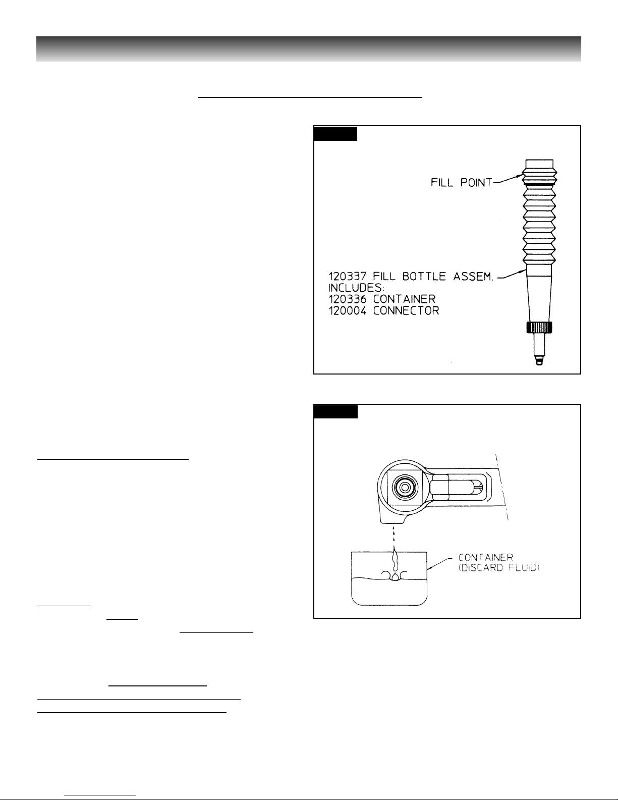
• Fill bottle, 120337, (supplied with
tool).
• Large flat blade screwdriver
• Nose assembly or optional stall nut
• Fasteners (optional)
• Optional stall nut and stop
Stall nut, 125340 and stop, 125341
Stall nut is used to load tool during bleeding
and for measuring stroke.
Preparation:
• Install air regulator in airline and set
pressure to 20 - 40 psi.
2. Fill bleed bottle almost full of
DEXRON III - - ATF (automatic
transmission fluid) - - see
FIGURE 3.
Procedure to Fill Empty T
ool (new or
rebuilt) - - as Applicable:
1. Attach the tool air source momentarily
to seat air piston at bottom of cylinder -
- disconnect tool. With fillport facing
up, lay tool on its side.
2. With a screwdriver, remove bleed
plug from fillport.
W
ARNING
Air pressure MUST be set to 20 - 40 psi to
prevent possible injurious high pressure
spray. Never cycle tool without bleed plug
tightened, fill bottle tightened in tool, or
fillport held over a receptacle (see
FIGURE 3.1). When not properly
contained any fluid present in tool will
spray out. Severe injury may result.
3. Screw fill bottle into fillport in the head.
4. Set airline pressure to 20-40 psi and
connect airline to tool.
FILLING AND BLEEDING PROCEDURE
Fig. 3
Fig. 3.1
Page 18
2015 TOOLING HUCK FASTENERS
13
5. Stand tool upright on bench. While
triggering tool slowly (20 - 30 cycles),
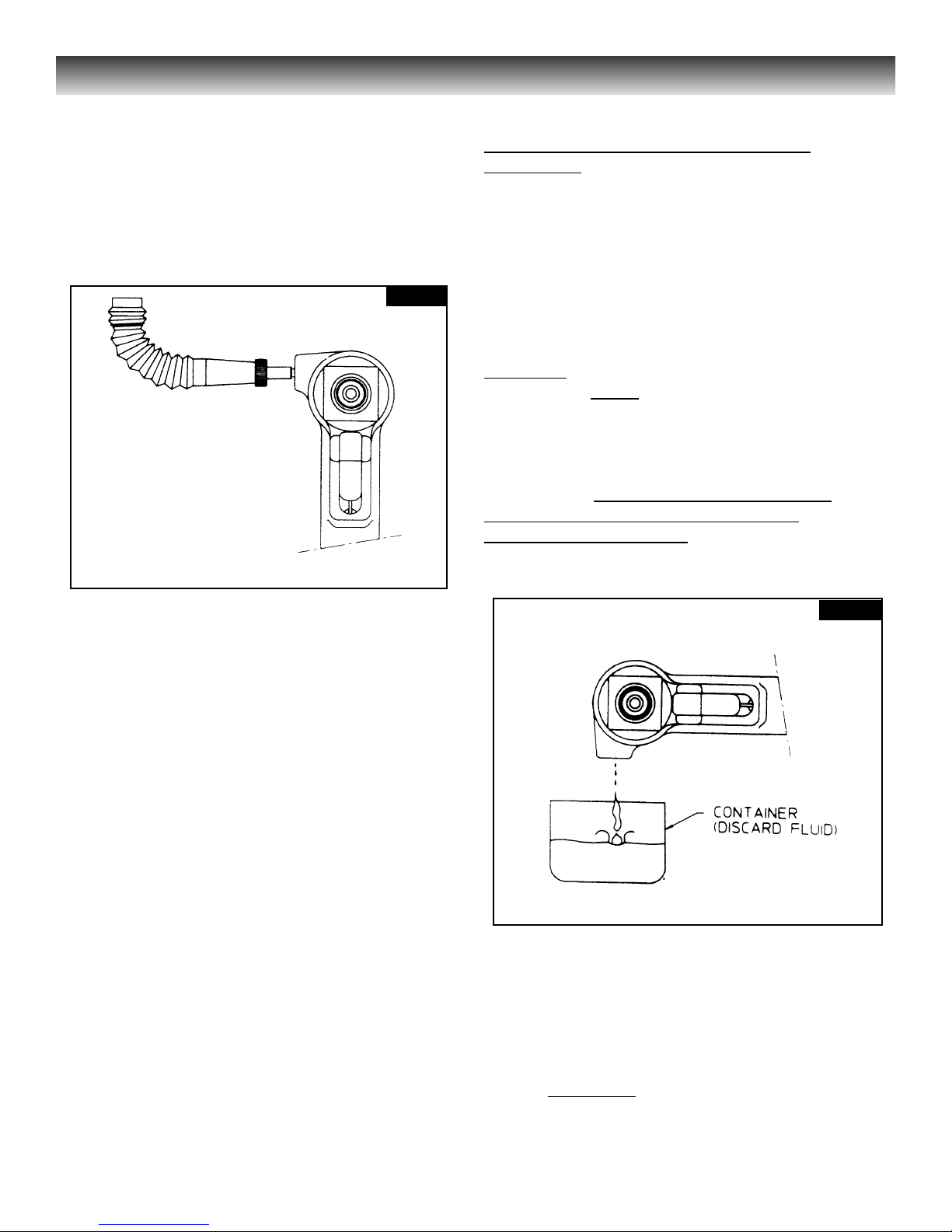
bend fill bottle at right angles to tool - see FIGURE 3.2. Air bubbles will
emerge from tool, When bubbles stop,
cycling may be discontinued.
6. When trigger is released, pull piston
returns to idle position (full forward).
Disconnect tool from airline.
7. Lay tool on its side. Remove fill
bottle. Top off fluid in fillport. Install
bleed plug and tighten.
8. Connect airline to tool. There is a choice
of two procedures for measuring the
stroke - - with and without a stall-nut - see appropriate section and follow the
selected procedure. If stroke is less than
specified, remove bleed plug and top off
fluid. Reinstall bleed plug.
9. Increase air pressure to specification.
Install two fasteners to check function
and installation in a single stroke, or
cycle tool with stall-nut fully threaded
onto piston to load up tool. Measure
stroke again. Remove plug and top off
fluid. Reinstall plug and cycle again - measure again. Continue this process
until stroke meets minimum requirements.
Bleed Procedure for Partially Filled Tool
in Field Use
- - as Applicable:
1. Disconnect tool from airline. With
fillport facing up, lay tool on its side.
2. Remove bleed plug from bleed port.
3. Hold tool over suitable container with
fillport facing into container.
W
ARNING
Air pressure MUST be set to 20 - 40 psi to
prevent possible injurious high pressure
spray. Never cycle tool without bleed plug
tightened, fill bottle tightened in the tool,
or the fillport held over a receptacle (see
FIGURE 3.3). When not properly contained
any fluid present in tool will spray out.
Severe injury may result.
4. Connect tool to airline. Cycle tool several
times to drain the old fluid, air and foam.
5. Screw fill bottle into fillport.
6. See W
ARNING above. With air pressure
set at 20-40 psi, connect airline to tool.
Fig. 3.3
Fig. 3.2
Page 19
2015 TOOLING HUCK FASTENERS
14
7. Stand tool upright on bench. While
actuating the trigger slowly (20 - 30
cycles), bend fill bottle at right angles to
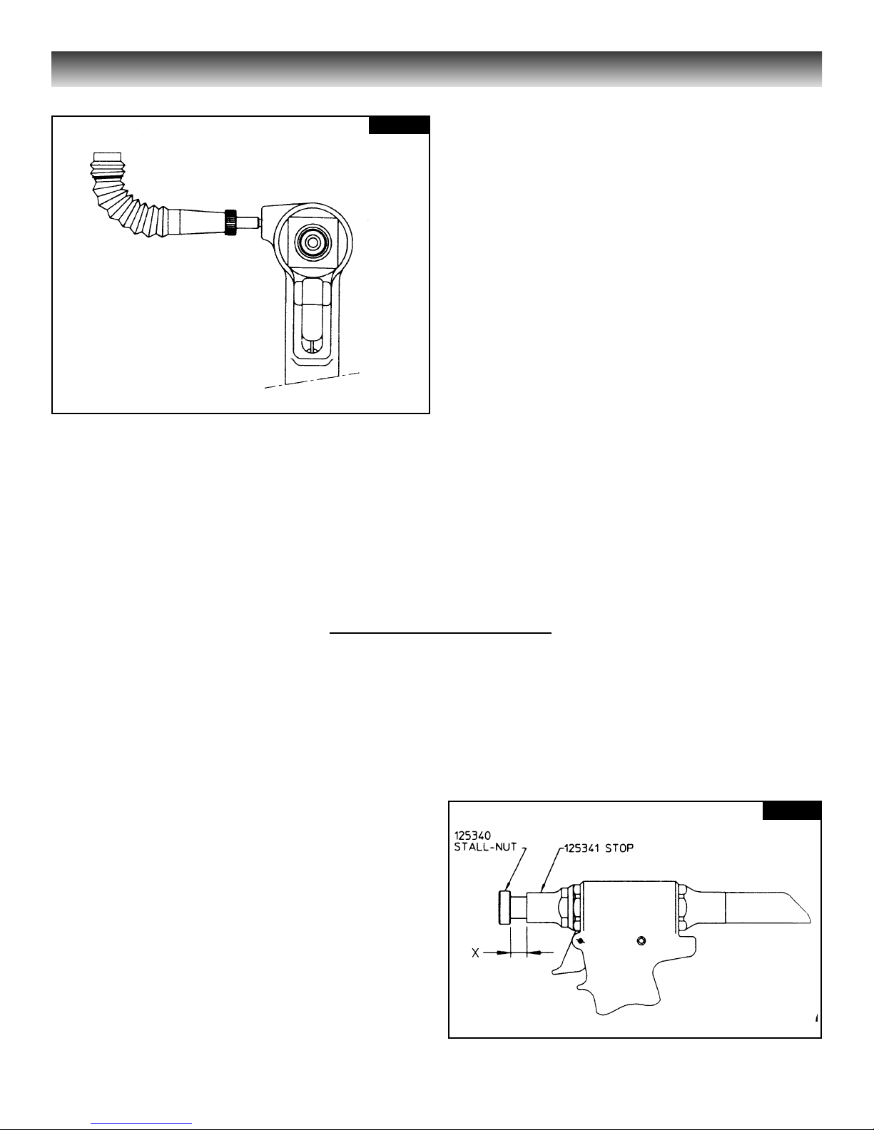
tool - - see FIGURE 3.4. Observe that air
bubbles emerge from tool. When bubbles
are no longer observed, cycling may be
discontinued.
8. When trigger is released, pull piston
returns to idle position (full forward).
Disconnect tool from airline with piston
full forward.
9. Lay tool on its side. Remove fill bottle.
Top off fluid in fillport. Install bleed plug
and tighten with screwdriver.
10. Connect airline to tool. There is a choice
of two procedures for measuring the
stroke - - with and without a stall-nut - see appropriate section and follow the
selected procedure. If stroke is less than
specified, remove bleed plug and top off
fluid. Reinstall bleed plug.
11. Install two fasteners to check function
and installation in a single stroke, or
cycle tool with stall nut fully threaded
onto piston. Measure stroke again.
Remove plug and top off fluid. Reinstall
plug and cycle again - - measure again.
Continue this process until stroke meets
minimum requirements.
Fig. 3.4
Fig. 3.5
1. Disconnect tool from airline - - remove
nose from tool.
2. With piston fully forward (end of
RETURN stroke), bottom the stall-nut
on piston- Back stall-nut off five (5)
turns.
3. Cycle tool and hold trigger depressed - this keeps piston fully to the rear and at
end of PULL stroke. Thread stall-nut
back onto piston until it contacts stop.
4. Release trigger. Stall-nut will move
forward with piston. See FIGURE 3.5
and measure ‘X” dimension. This is the
tool’s stroke.
To measure stroke of tool with stall-nut
threaded onto piston:
How to Measure S
troke
5. If stroke is less than .650, refer to
appropriate previous section. Follow’
filling and topping off instructions.
Page 20
2015 TOOLING HUCK FASTENERS
15
To measure stroke of tool without
stall-nut:
1. Disconnect tool from airline - - remove
nose from tool.
2. With piston fully forward (end of
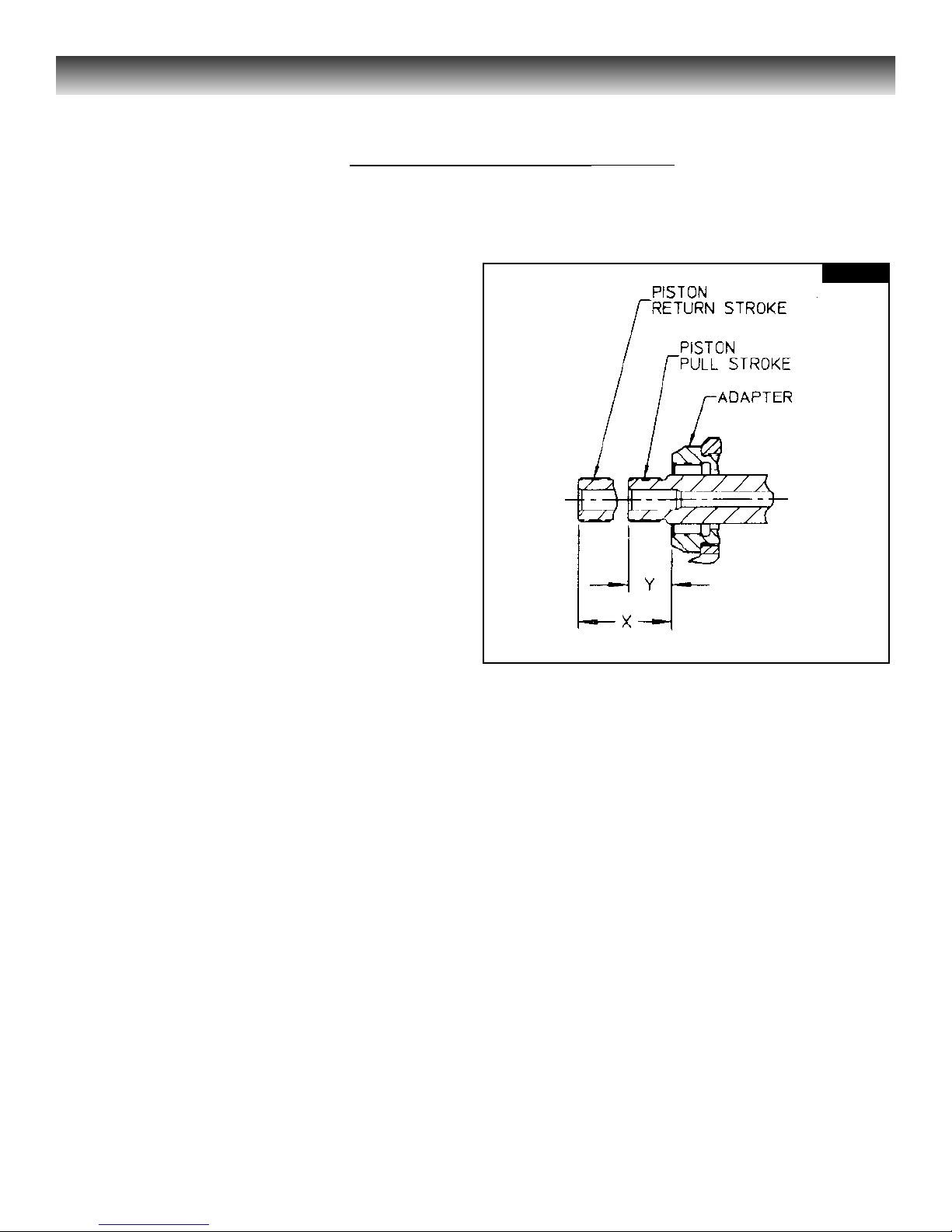
RETURN stroke), measure and record
“X” dimension - - see FIGURE 3.6.
3. Hold trigger depressed. Piston is now
fully to the rear and at end of PULL
stroke. Measure and record “Y”
dimension.
5. Subtract “X” dimension from “Y”
dimension.
6. If stroke is less than .650, refer to
appropriate previous section. Follow
filling and topping off instructions.
How to Measure Stroke (continued)
Fig. 3.6
-------------------- S
ERVICE N
OTES: ---------------------
Page 21

2015 TOOLING HUCK FASTENERS
16
Symptom
1. Tool fails to operate
when triggered.
2. Tool does not complete fastener
installation or break pintail.
3. Hydraulic fluid exhausts with air.
4. Hydraulic fluid leaks at
Cylinder Head End Cap.
5. Hydraulic fluid leaks
at Pull Piston Rod.
6. Pull Piston will not return.
7. Air leaks at Air Cylinder Head.
Probable cause
a. Throttle valve O-rings (3)
worn or damaged.
b. Air pressure too low.
c. Throttle cable assembly broken.
a. Air pressure too low.
b. Hydraulic fluid low,
causing short stroke.
c. Air piston QUAD ring
worn or damaged.
d. Air in hydraulic system - -
see FILLING AND BLEEDING.
e. Collet backed off from Piston.
a. Worn or damaged O-rings,
POLY-SEAL and/or QUAD ring
in Gland Assembly, 116134-1.
a. Worn or damaged Pull Piston
O-ring/back-up ring.
a. Worn or damaged Front Gland
POLY-SEAL and wiper,
and/or O-ring.
a. Broken or weak Return Spring.
b. Collet backed off from Piston.
a. Cylinder Head O-ring damaged.
Troubleshooting
Always check out the simplest possible cause of a malfunction first. For example, an air
hose not connected. Then proceed logically, eliminating each possible cause until the
defective part is located. Where possible, substitute known good parts for suspected bad
parts. Use this chart to help locate and correct malfunction:
Spare Parts and Service Kits
The quantity of spare parts that should be kept on hand varies with application
and number of tools in service. Service kits containing perishable parts such as
POLY-SEALS, O-rings, back-up rings, etc., should be kept on hand at all times.
See listing of contents of SERVICE KIT, 2015KIT and 2015VKIT.
Page 22

2015 TOOLING HUCK FASTENERS
17
Refer to MAINTENANCE: GOOD
SERVICE PRACTICE, FIGURES 4, 5, 6, 7,
8, 9, 10, 11, and 12.
W
ARNING
Air hose must be disconnected before:
• Removing or attaching nose
assembly.
• Cleaning tool and/or nose assembly.
• Replacing worn or damaged tool
components.
Tool may be activated if not disconnected
and cylinder is under pressure. Fingers
may be severely pinched/lacerated. Other
severe personal injury may result.
The following procedure is for complete
disassembly - - disassemble only subassemblies necessary to check and replace
damaged or worn seals, wipers, back-up
rings and other components.
Always replace seals, wipers, and back-up
rings of disassembled sub-assemblies.
1. Disconnect tool from air source.
2. Unscrew Retaining Nut and remove
nose assembly.
3. Unscrew Bleed Plug, including O-ring,
from top of Handle/head. Turn tool
over and allow fluid to drain into
container - - tool may be cycled to clear
tool more completely. Discard fluid.
4. Pull Pintail Deflector off End Cap.
5. Remove Throttle Arm Pivot Screw and
lift out throttle arm. Disconnect ball
end of Cable Assembly from throttle
arm.
6. Hold tool in vise with bottom up.
Remove Button Head Screws (3) with
1/8 hex key. Remove End Cap and
Gasket. Remove Muffler from end cap.
Remove Spring from Throttle Valve.
7. To loosen Cylinder Head Retaining
Ring in Cylinder, tap Cylinder Head
with mallet. Remove Retaining Ring.
8. NOTE: Screw Button Head Screws
back into Cylinder Head. Carefully pull
or pry on screws to remove head.
9. To remove air piston from cylinder,
pull on Lock Nut with VISE-GRIP
pliers.
Note: Air piston and rod should not
be disassembled and reassembled. If
lock nut loosens, apply LOCTITE #271
and tighten to 25-30 ft. lbs.
CAUTION
DO NOT SCRATCH, NICK OR DING
PISTON ROD. THIS WILL CAUSE
PERMANENT HYDRAULIC LEAKAGE.
10.Remove Bumper from Gland
Assembly. Unscrew gland with 1 3/8
socket wrench and extension bar.
11. Remove SPIRO-LOX Retaining Ring
from gland. Pull out Spacer and
POLYSEAL.
12.Lift cylinder from handle/head.
13.Turn handle/head over - - drain fluid
into container. Discard fluid.
14.Pull Throttle Valve out of cylinder.
DISASSEMBLY
Page 23

2015 TOOLING HUCK FASTENERS
18
15. Service on Throttle Valve Bushings
not normally required.
CAUTION
ONLY IF AIR LEAKAGE IS NOT
CORRECTABLE WITH NEW
THROTTLE VALVE SEALS, BUSHINGS
SHOULD BE REPLACED IN CYLINDER.
Press out Lower Bushing and Upper
Bushing. Use square ended brass
rods at least six inches long. With
proper diameter rod, press out lower
bushing first, and then, press out
upper bushing using a larger size rod.
16. Place handle/head securely in vise.
Remove End Cap with 15/16” open
end wrench. Extract Spring, Washer
and Wiper Seal.
17. Head/handle Disassembly using:
Optional Assembly Tool Kit,
123110-4, which includes:
• POLYSEAL Insertion and Removal
Tool, 121694-202
• Piston Assembly (bullet)
Tool,123111-4
• Spacer, 123112-3
Kit is used for disassembly and
assembly.
CAUTION
If Piston Seals and Gland Seals must be
reused, help prevent damaging them at
disassembly by installing OPTIONAL
POLYSEAL Insertion/removal Tool
(121694-202) in rear of Handle/head.
If replacement seals are not available,
use seal insertion/removal tool to
help prevent seal damage - - undamaged
used seals are not a personal safety
problem.
REMOVAL OF PISTON AND FRONT GLAND
see FIGURE 12
17.1 Thread POLYSEAL
Insertion/removal Tool, 121694-202,
into Handle/head.
17.2 Slide Spacer, 123112-3, onto piston.
Thread Piston Assembly (bullet)
Tool, 123111-4 onto piston.
17.3 Push complete piston from front
using brass drift. Allow clearance,
with stand-off, for piston as it leaves
tool.
17.4 Remove Piston Assembly Bullet,
Spacer and POLYSEAL
Insertion/removal Tool.
NOTE: Inspect hydraulic piston for
wear, scoring or damage. Replace
when necessary.
18. Unscrew Adapter, 125132, with wrench.
19. Inspect all seals and parts.
20. Remove trigger cable assembly by
removing pin with parallel punch.
Remove dowel pin to disconnect
cable from trigger.
DISASSEMBLY (CONTINUED)
Page 24
2015 TOOLING HUCK FASTENERS
19
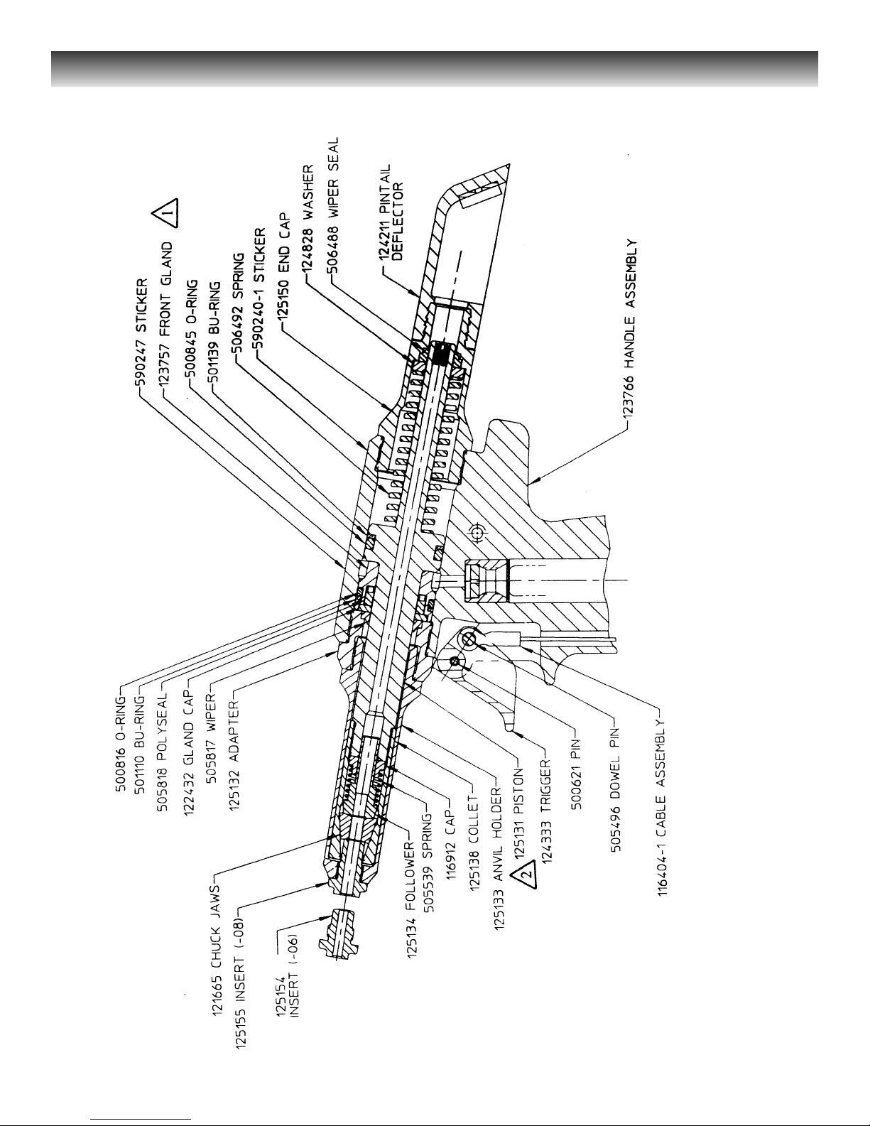
Figure 4 - 2015 Head/handle
Page 25
2015 TOOLING HUCK FASTENERS
20
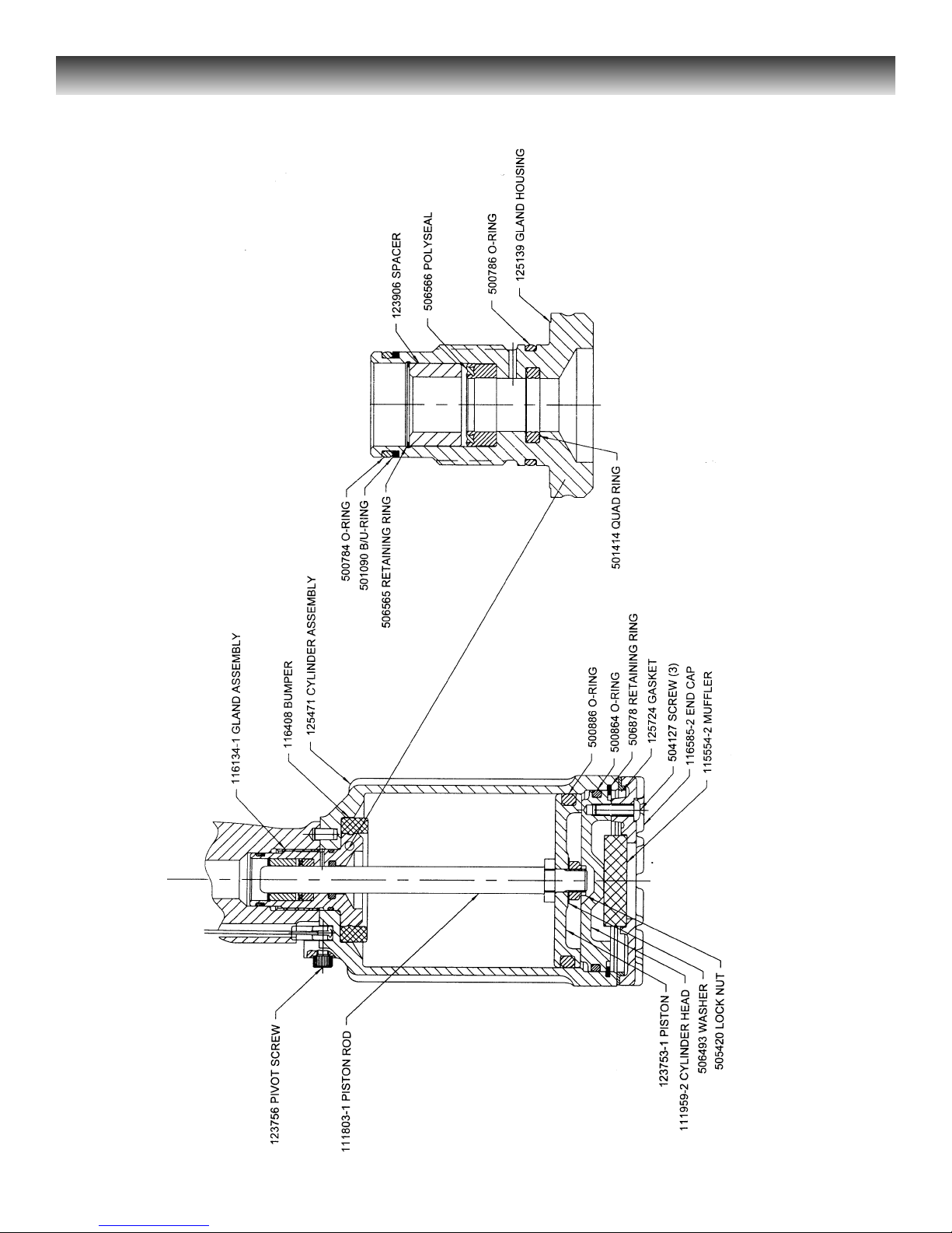
Figure 5 - 2015 Air Cylinder
Fig. 5.1 - 116134-1 GLAND ASSEMBLY
Page 26
2015 TOOLING HUCK FASTENERS
21
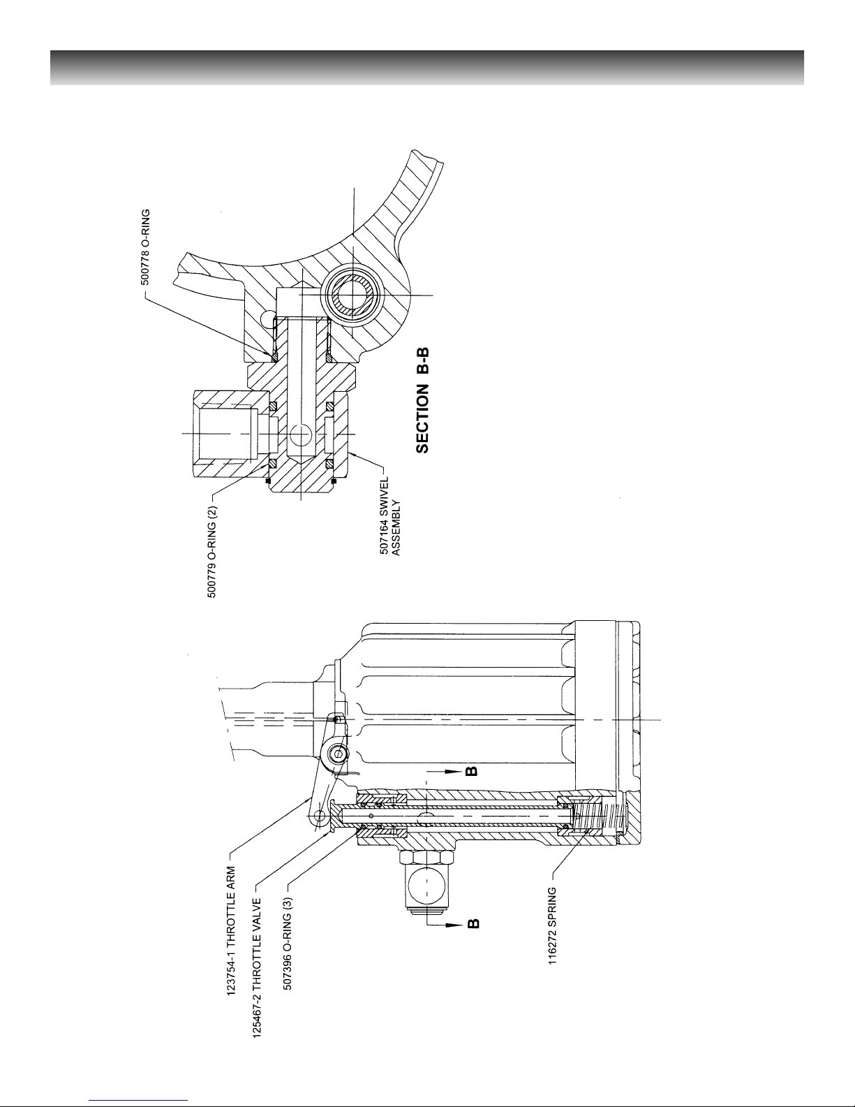
Figure 6 - Throttle Valve Sub-assembly and Related Compoments
Page 27
2015 TOOLING HUCK FASTENERS
22
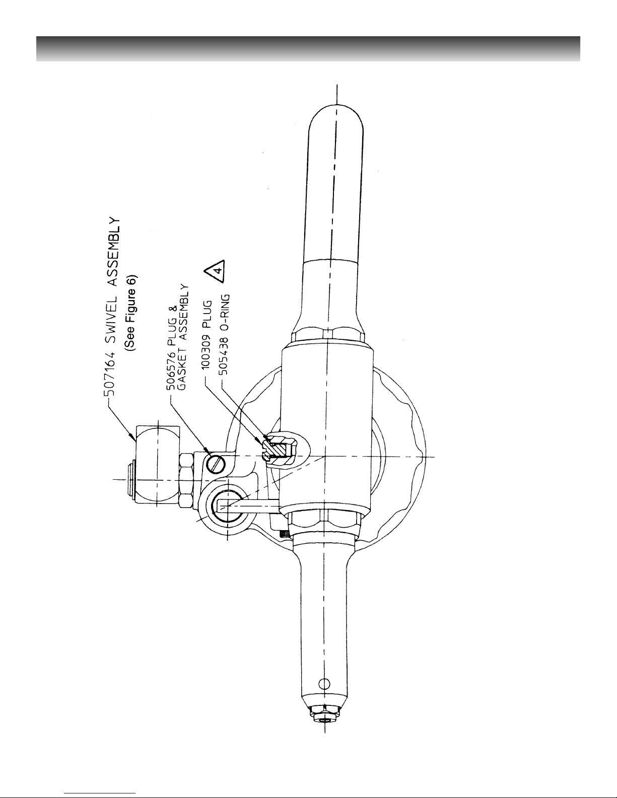
Figure 7 - Swivel Bolt Sub-assembly
Fill Plug and O-ring Sub-assembly
Page 28
2015 TOOLING HUCK FASTENERS
23
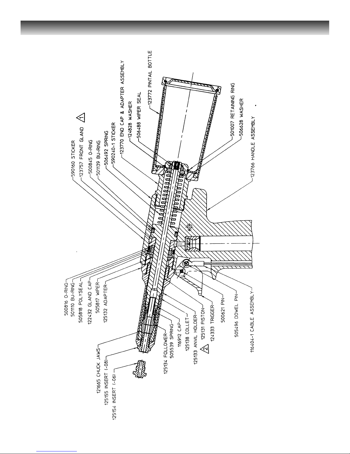
Figure 8 - 2015B Head/handle
Page 29
2015 TOOLING HUCK FASTENERS
24
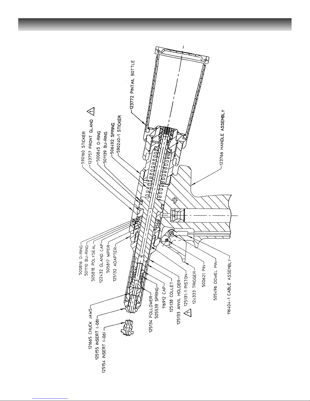
Figure 9 - 2015V Head/handle
Page 30
2015 TOOLING HUCK FASTENERS
25
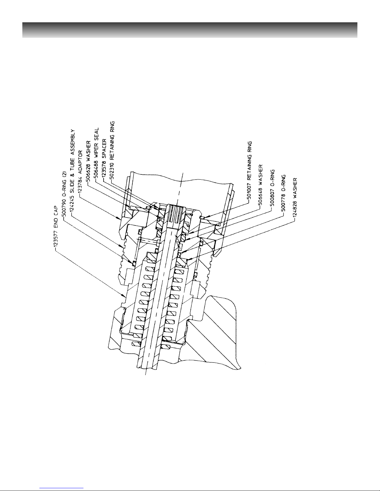
Figure 10 - 2015V Assembled Vacuum Attachment
Page 31
2015 TOOLING HUCK FASTENERS
26
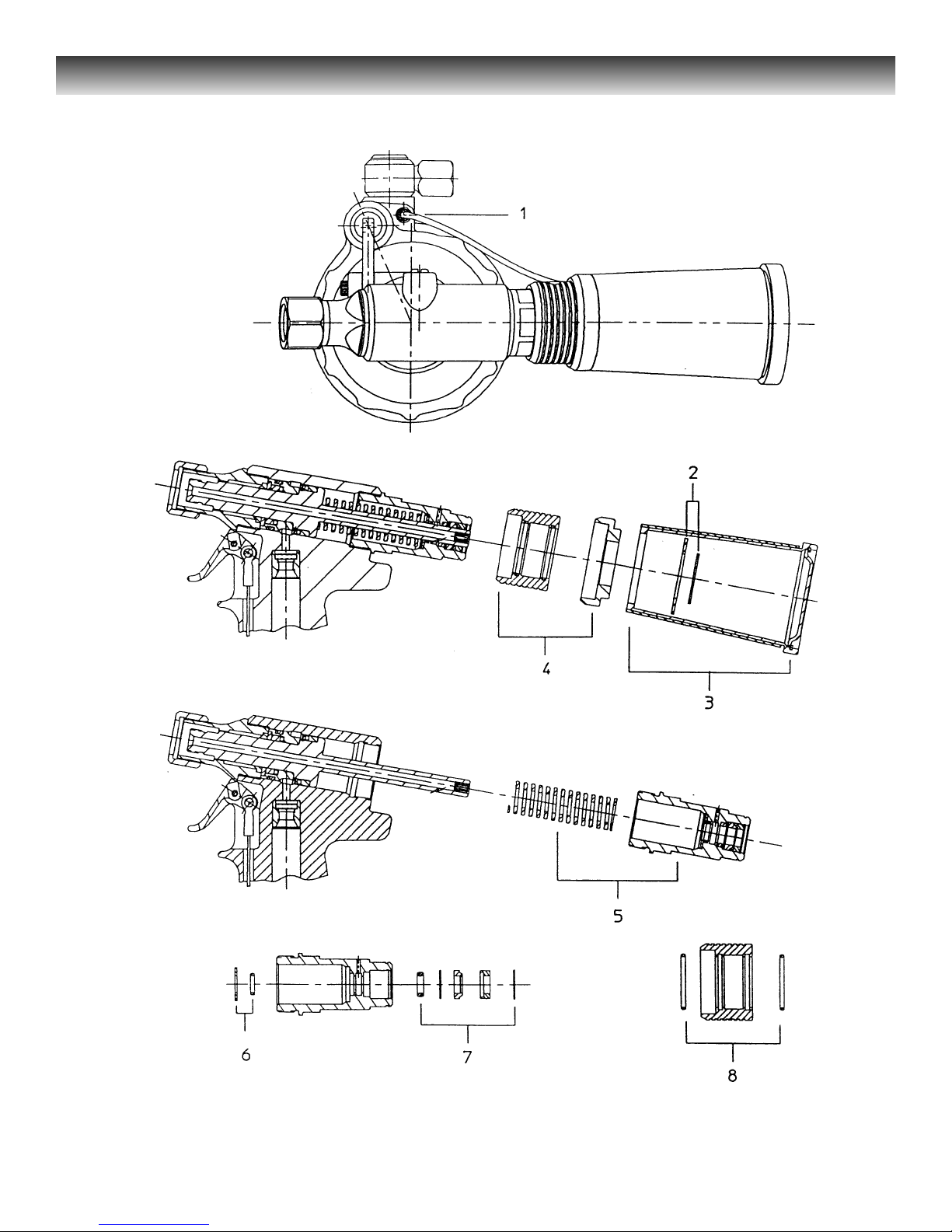
Figure 11 - Exploded View of Vacuum Attachment
Page 32

2015 TOOLING HUCK FASTENERS
27
The following paragraphs from one
through eight are for 2015V. Paragraphs
two and three are for both 2015B and 2015V.
Remaining instructions are in the
general DISASSEMBLY and ASSEMBLY
sections. Paragraph numbers below match
the exploded view’s reference numbers.
Always replace seals, wipers and back-up
rings of disassembled sub-assemblies.
1. Disconnect air line at cylinder.
2. 2015B and 2015V
:
Use 0100 TRUARC p!iers, 502857, to
remove retaining ring - - reach through
window of pintail bottle. Remove washer.
3. 2015B and 2015V
:
Remove pintail bottle.
4. Remove bottle adapter and vacuum
ON/OFF slide.
5. Remove end cap assembly and spring.
6. Remove washer and O-ring from spring
side of end cap.
7. Remove retaining ring on bottle side of
end cap. Remove spacer, wiper seal,
washer and O-ring.
8. Remove O-rings from ON/OFF slide.
Reverse the order of disassembly for
assembling components.
-------------------- S
ERVICE N
OTES: ---------------------
DISASSEMBLY & ASSEMBLY
2015B Pintail collector
2015V Collector/vacuum Boost
Page 33
2015 TOOLING HUCK FASTENERS
28
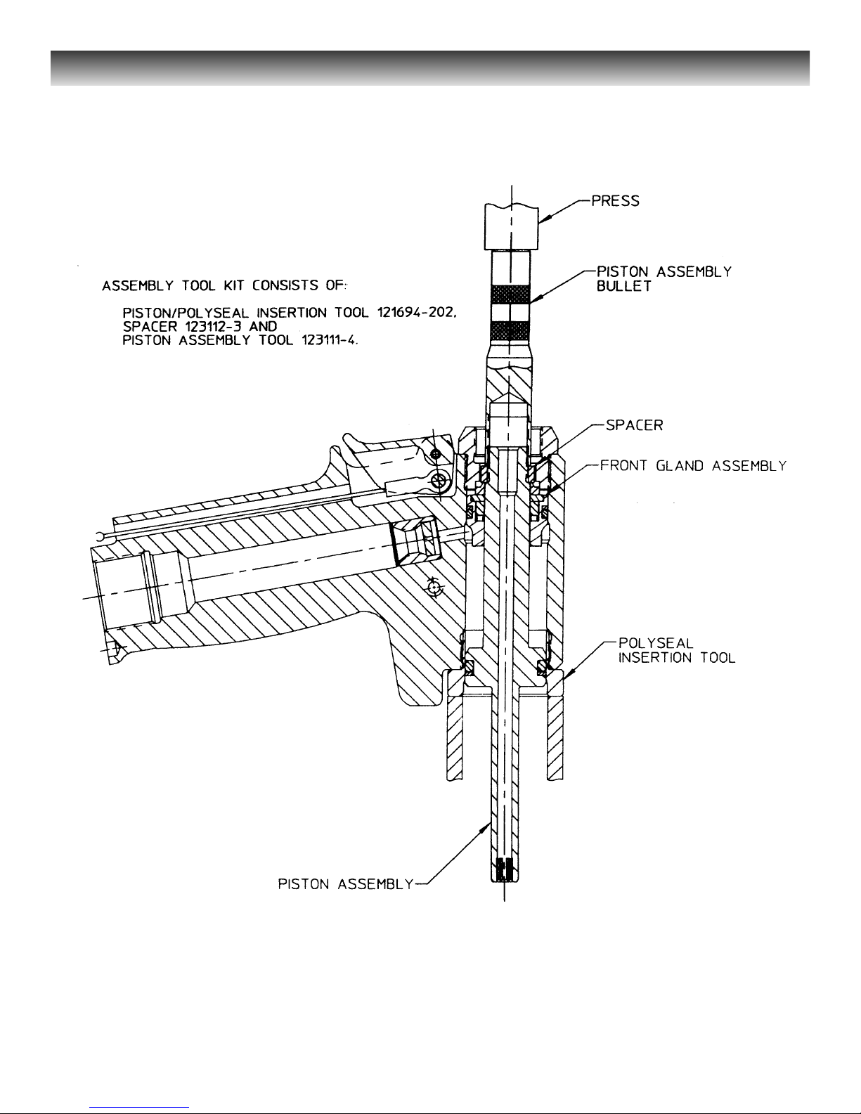
Figure 12 - Removing Piston and Front Gland
Page 34
2015 TOOLING HUCK FASTENERS
29
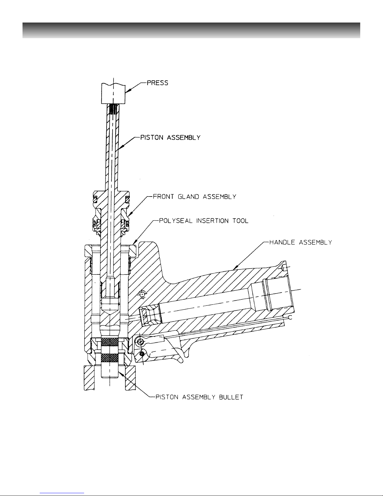
Figure 13 - Installing Piston and Front Gland
Page 35

2015 TOOLING HUCK FASTENERS
30
Disassembly/assembly using Optional Piston Assembly Kit, 123110-4, and
Optional Damper removal Tool, 123769
Optional Assembly Tool Kit, 123110-4, includes:
(Kit is used for disassembly and assembly)
* POLYSEAL Insertion/removal Tool, 121694-202
* Piston Assembly (bullet) Tool, 123111-4;
* Spacer, 123112-3.
Disassembly of Piston from tool - see FIGURE 12- PISTON REMOVAL
1. Thread POLYSEAL Insertion/removal
Tool, 121694-202, into Handle/head.
2. Slide Spacer, 123112-3, onto piston.
Thread Pistin Assembly (bullet)
Tool, 123111-4 onto piston.
3. Push complete piston from front using
brass drift. Allow clearance, with standoff, for piston as it leaves tool.
4. Remove Piston Assembly (bullet) Tool,
Spacer and POLYSEAL
Insertion/removal Tool.
Assembly of Piston to tool - see FIGURE 13- PISTON ASSEMBLY
1. Thread POLYSEAL Insertion/removal
Tool, 121694-202, into handle/head.
2. Thread Piston Assembly (bullet) Tool,
123111-4, onto piston assembly.
3. Push front gland assembly onto piston,
as shown.
4. Slide wiper onto piston, as shown.
5. Install adapter into front of head. Push
assembled components in gently from
rear of tool using a press, or a soft mallet
and wood or brass drift.
6. Remove Piston Assembly (bullet) Tool
and POLYSEAL Insertion/removal
Tool.
-------------------- S
ERVICE N
OTES: ---------------------
Page 36

See MAINTENANCE: GOOD SERVICE
PRACTICE, FIGURES 4, 5, 6, 7, 8, 9,
10,11and 13.
Clean all components with mineral spirits,
and inspect for wear or damage.
Replace as necessary.
CAUTION
Always replace all seals, wipers and backup rings on/in disassembled components.
These parts wear from friction and
deteriorate with age - - replacement
prevents potential leakage.
Use seals, wipers and back-up rings supplied
in SERVICE KIT, 2015KIT -see NOTES.
Smear LUBRIPLATE 13OAA or PARKER-O-LUBE on
seals.
1. If Bushings have been removed
from cylinder:
Use an arbor press and apply
LOCTITE #609, (503377) on bushings
before being pressed into cylinder.
Place chamfered end of Upper Bushing
In top of Cylinder. Carefully press
bushing squarely into cylinder. Repeat
procedure for Lower Bushing.
2. Assemble Gland Assembly - see FIGURE 5.1.
NOTE: Cup of POLYSEAL must
face toward top of tool when
installed in Gland.
Replace POLYSEAL, Spacer and
SPIRO-Lox Retaining Ring.
3. Assemble Handle/head Assembly
(using optional Piston Assembly
Kit, 123110-4) after 3.1.
3.1 Install Adapter into cylinder
handle/bead.
31
2015 TOOLING HUCK FASTENERS
INSTALLING PISTON AND FRONT
GLAND - - see FIGURE 9
3.2 Thread POLYSEAL
Insertion/removal Tool,
121694-202, into handle/head.
3.3 Thread Piston Assembly (bullet) Tool,
123111-4, onto piston assembly.
3.4 Push front gland assembly onto
piston, as shown.
3.5 Slide wiper onto piston, as shown.
3.6 Push assembled components in gently
from rear of tool using a press, or a soft
mallet and wood or brass drift.
3.7 Remove Piston Assembly (bullet) and
POLYSEAL Insertion/removal Tool.
4. Assemble Spring, Spacer, Rear Wiper
Seal and End Cap into handle/head.
5. See FIGURE 4 - - position Cable
Assembly in Trigger slot and push
Dowel Pin through holes in trigger and
cable assembly. Position assembled
trigger in handle and push Pin through
holes in handle and trigger.
6. Hold handle/head in vise with
lower end pointing up. Turn
cylinder bottom up, and position on
handle by lining up cylinder pin
with handle hole.
7. Apply VIBRATITE or equivalent to threads
of Gland Assembly. Screw gland into
head/handle. Using 1 3/8 socket wrench,
tighten gland to 75-80 ft. lbs.
8. Push Bumper firmly over gland, slots must
face toward bottom of tool.
ASSEMBLY
Page 37

9. Lubricate piston rod. Press assembled
air piston/piston rod into cylinder just
enough to allow installation of cylinder
head.
10. Push Cylinder Head squarely into
cylinder taking care not to damage
O-ring. Install spiral Retaining Ring.
Align screw holes with muffler end cap.
11. Position Muffler in center of cylinder
head. Position Gasket on cylinder.
12. Carefully position Muffler End Cap
on cylinder - - be certain that muffler
is properly positioned in recess of
muffler end cap.
13. Muffler end cap is secured with three
Button head Screws - tighten with
1/8 hex key.
14. Place tool upright on level surface.
Drop Spring into throttle valve bore in
cylinder. Push Throttle Valve into cylinder.
32
2015 TOOLING HUCK FASTENERS
15. Place ball end of Throttle Cable in
end of Throttle Arm.
16. Slide Throttle Arm into slot on Cylinder.
17. Install Pivot Screw in cylinder to
retain throttle arm.
18. Follow FILL AND BLEED PROCEDURE
to fill tool - - see appropriate section.
19. Install Bleed Screw after FILL AND
BLEED PROCEDURE.
20. Screw Anvil Insert into Anvil Holder.
21. Assemble components into Collet, as
shown in FIGURE 4. Screw assembled
collet onto piston rod - - tighten securely.
22. Screw assembled anvil holder and insert
into Adapter.
ASSEMBLY (CONTINUED)
-------------------- SERVICE NOTES: ---------------------
Page 38

1 123775 Front Gland sub-assembly includes:
(1) Front Gland Housing
500816 O-ring
501110 back-up ring
505818 POLY-SEAL
122432 Gland Cap
505817 wiper
2 125156 Piston sub-assembly includes:
(1) Piston
500845 O-ring
501139 back-up ring
3 123777-2 Air Piston and Rod sub-assembly includes:
(1) Air Piston
501451 QUAD ring
111803-1 Piston Rod
506493 flat washer - - .38 ID; .751 OD
505420 self-Iocking nut - - .38-24 thin SS
4 104293 Bleed Plug sub-assembly includes:
(1) Bleed Plug
505438 O-ring
5 123778-1 Cylinder Head sub-assembly includes:
(1) Cylinder Head
500864 O-ring
6 123779-1 Throttle Valve sub-assembly includes:
(1) Throttle Valve
504408 O-ring
504407 O-ring
7 125156-1 Piston sub-assembly includes:
(1) Piston
500845 O-ring
501139 back-up ring
8. CAUTION: Install cups of POLY-SEALS positioned as shown;
position wipers as shown.
(I) Purchase sub-assembly when this part (I) is required.
33
2015 TOOLING HUCK FASTENERS
Sub-assembly Part Numbers and Notes
Refer to illustrations
Page 39

Specifications for Standard Parts
I. All part numbers shown are available from Huck. The 500000
series part numbers are standard parts which generally
can be purchased locally.
2. O-ring sizes are specified AS 568 dash numbers.
(AS 568 - is an AEROSPACE SIZE STANDARD FOR O-RINGS
and formerly was known as ARP -).The listing of SERVICE KIT,
2015KIT has specific material and durometer just after the identifying
AS 568 - dash numbers.
3. QUAD ring sizes are specified Q4 plus 3 digits. The last 3 digits
correspond to O-ring dash numbers. QUAD rings are manufactured
by Minnesota Rubber Co. unless otherwise specified.
4. Back-up rings are W. S. Shamban & Co. series S-11248,
single turn Teflon (MS-28774), or equivalent. The dash numbers
correspond to the O-ring AS 568 - dash numbers.
34
2015 TOOLING HUCK FASTENERS
-------------------- SERVICE NOTES: ---------------------
Page 40
35
MODEL 2015 TOOL All Models HUCK FASTENERS
ACCESSORIES
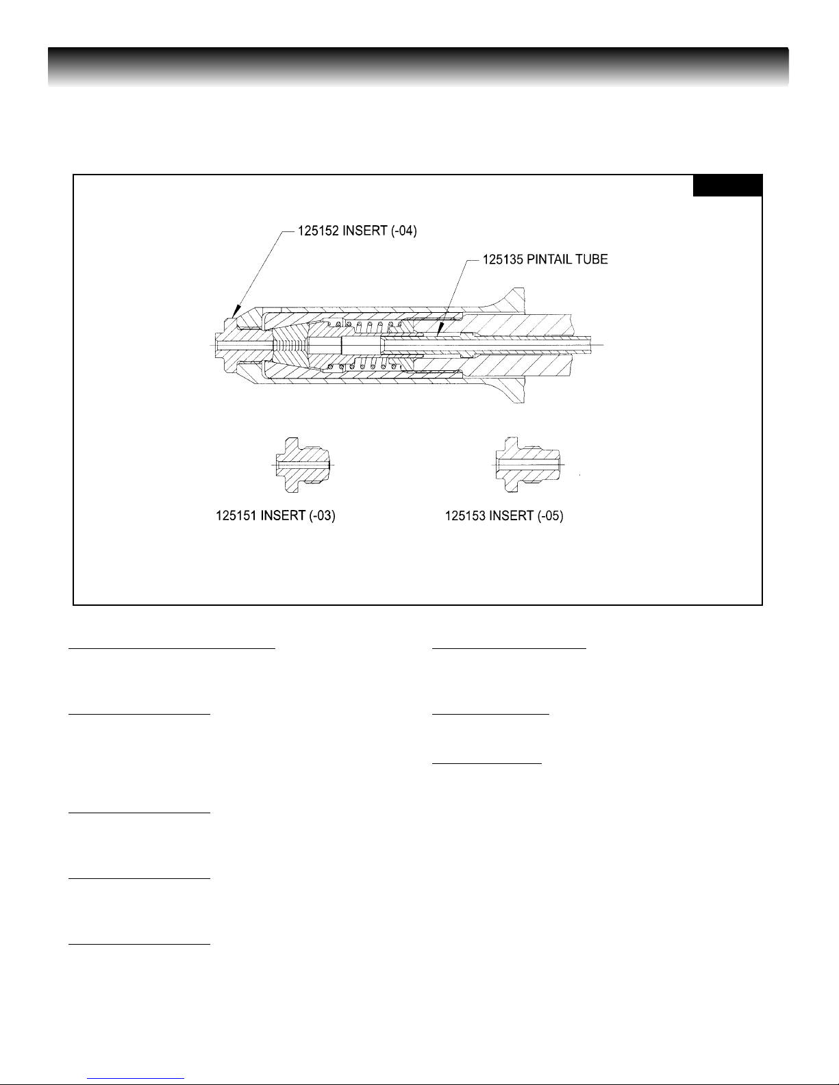
Anvil Inserts Included with Tool
125154 -06 Nail Type Driving Anvil Insert
125155 -08 Nail Type Driving Anvil Insert
Accessory Kit 125273
125135 Pintail Tube
125152-04 Nail Type Driving Anvil Insert
125153-05 Nail Type Driving Anvil Insert
125151-06 Nail Type Driving Anvil Insert
Accessory Kit 125367
125283 -06 Peel Rivet Driving Anvil Insert
125284 -08 Peel Rivet Driving Anvil Insert
Accessory Kit 125365
125279 -06 MOL Truss Head Anvil Insert
125154 -06 MGL Countersunk Anvil Insert
Accessory Kit 125366
125280 -06 MGT Protruding Head Anvil Insert
125281 -06 MGT Button Head Anvil Insert
125154 -06 MGT Flat Head Anvil Insert
Accessory Kit 125366-1
125155 -08 MGT Flat Head Anvil Insert
125282 -08 MGT Protruding Head Anvil Insert
Accessory S
pring
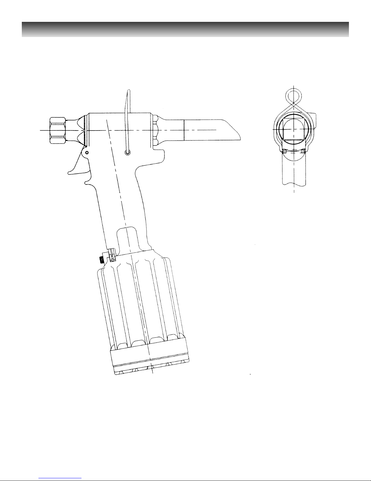
124447 Suspension Spring (see Fig. 15, p. 38)
Assembly Tools:
124090-2 Stall NutAssembly
123110-4 Assembly Tool Kit
Includes:
121694-202 POLYSEAL Insertion Tool
123111-4 Piston Assembly Tool
123112-3 Spacer
Anvil Inserts Used with Pintail Tube
(Kit 125273 - see below)
FIG.14
Page 41

Service Kit, 2015KIT, for 2015 and 2015B
Part No. Qty Description
505817 1 Wiper seal MICRODOT #D-0625
506488 1 Wiper seal DISO. #006-005
505818 1 POLYSEAL MD #125-00.625-250B
506566 1 POLYSEAL MD #125-00.437-250B
501414 1 QUAD ring MR-Q4111
501451 1 QUAD ring MR-Q4333
500816 1 O-ring AS568-119 C366Y 70D
500864 1 O-ring AS568-232 C366Y 70D
500784 1 O-ring AS568-018 C366Y 70D
500786 1 O-ring AS568-020 C366Y 70D
500778 1 O-ring AS568-012 C366Y 70D
500779 1 O-ring AS568-013 C366Y 70D
500845 1 O-ring AS568-212 C366Y 70D
504408 2 O-ring AS568-012 CV747 75D
504407 1 O-ring AS568-011 CV747 75D
501110 1 Back-up ring S-11248-119
501090 1 Back-up ring S-11248-18
501139 1 Back-up ring S-11248-212
116272 1 Spring
506565 1 Internal Retaining Ring UR-068
8-2015 1 Model 2015 assembly drawing
Accessory S
pring
Suspension Spring, 124447, is available separately.
See FIGURE 14 on page 38.
36
2015 TOOLING HUCK FASTENERS
Page 42

Service Kit, 2015VKIT
Part No. Qty Description
505817 1 Wiper seal MICRODOT #D-0625
506488 1 Wiper seal DISO. #006-005
505818 1 POLYSEAL MD #125-00.625-250B
506566 1 POLYSEAL MD #125-00.437-250B
501414 1 QUAD ring MR-Q4111
501451 1 QUAD ring MR-Q4333
500790 1 O-ring AS568-024 C366Y 70D
500816 1 O-ring AS568-119 C366Y 70D
500864 1 O-ring AS568-232 C366Y 70D
500784 1 O-ring AS568-018 C366Y 70D
500786 1 O-ring AS568-020 C366Y 70D
500778 1 O-ring AS568-012 C366Y 70D
500779 1 O-ring AS568-013 C366Y 70D
500845 1 O-ring AS568-212 C366Y 70D
500807 1 O-ring AS568-110 C366Y 70D
504408 2 O-ring AS568-012 CV747 75D
504407 1 O-ring AS568-011 CV747 75D
505438 1 O-ring AS568-006 C9250 90D
501110 1 Back-up ring S-11248-119
501090 1 Back-up ring S-11248-18
501139 1 Back-up ring S-11248-212
116272 1 Spring
506565 1 Internal Retaining Ring UR-068
502310 1 Internal Retaining Ring RR-62
8-2015 1 Model 2015 assembly drawing
37
2015 TOOLING HUCK FASTENERS
Page 43
2015 TOOLING HUCK FASTENERS
38
Figure 15 - 2015 with Suspension Spring, 124447
Page 44

----------------------------------------------------------------------------
1. CHEMICAL PRODUCT/COMPANY IDENTIFICATION
----------------------------------------------------------------------------
HYDROCLEAR(R) DEXRON(R) III/MERCON(R) Automatic Transmission Fluid
MSDS Code: ATFC0089 Revised: 14-Mar-2000
"HYDROCLEAR" is a registered trademark of Conoco.
"DEXRON" is a registered trademark of General Motors Corp.
"MERCON" is a registered trademark of Ford Motor Company.
Product Use: Automatic Transmission Fluid
Conoco Blend Code: 46682
MANUFACTURER/DISTRIBUTOR
Conoco Inc.
P.O. Box 2197
Houston, TX 77252
PHONE NUMBERS
Product Information: 1-281-293-5550
Transport Emergency: CHEMTREC 1-800-424-9300 (U.S. & Canada)
703-527-3887 (elsewhere; call collect)
Medical Emergency: 1-800-441-3637
-------------------------------------------------------------------------
2. COMPOSITION/INFORMATION ON INGREDIENTS
-------------------------------------------------------------------------
COMPONENTS %
Base oils >85
Proprietary additives <15
If oil mist is generated, exposure limits apply (see Section 8).
-------------------------------------------------------------------------
3. HAZARDS IDENTIFICATION
-------------------------------------------------------------------------
--- EMERGENCY OVERVIEW --APPEARANCE / ODOR
Red liquid / mild petroleum hydrocarbon odor.
OSHA REGULATORY STATUS
This material is classified as nonhazardous under OSHA Regulations.
HMIS RATING
Health: 1; Flammability: 1; Reactivity: 0
___________________________________
Potential Health Effects
Primary Route of Entry: Skin
The product, as with many petroleum products, may cause minor skin, eye, and
lung irritation, but good hygienic practices can minimize these effects.
Normal use of this product does not result in generation of an oil mist. However if
an oil mist is generated, overexposure can cause minor and reversible irritation to
the eyes, skin, and especially the lungs. Proper personal protective equipment
and sufficient ventilation can provide adequate protection.
Carcinogenicity Information
None of the components present in this material at concentrations equal to or
greater than 0.1% are listed by IARC, NTP, OSHA or ACGIH as a carcinogen.
------------------------------------------------------------------------
4. FIRST AID MEASURES
------------------------------------------------------------------------
INHALATION
If inhaled, remove to fresh air. If not breathing, give artificial respiration. If breathing is difficult, give oxygen. Call a physician.
SKIN CONTACT
Wash skin thoroughly with soap and water. If irritation develops and persists, consult a physician.
EYE CONTACT
In case of contact, immediately flush eyes with plenty of water for at least 15 minutes. Call a physician.
INGESTION
Material poses an aspiration hazard. If swallowed, do not induce vomiting.
Immediately give 2 glasses of water. Never give anything by mouth to an unconscious person. Call a physician.
If vomiting occurs naturally, have victim lean forward to reduce the risk of aspiration.
Notes to Physicians
Activated charcoal mixture may be administered. To prepare activated charcoal
mixture, suspend 50 grams activated charcoal in 400 mL water and mix thoroughly. Administer 5 mL/kg, or 350 mL for an average adult.
---------------------------------------------------------------------------
5. FIRE FIGHTING MEASURES
---------------------------------------------------------------------------
Flammable Properties
Flash Point (typical): 370 F (188 C)
Flash Point (minimum): 351 F (177 C)
Method: COC
NFPA Classification: Class IIIB Combustible Liquid.
NFPA Rating: Health 0; Flammability 1; Reactivity 0
Extinguishing Media
Water Spray, Foam, Dry Chemical, CO2.
Fire Fighting Instructions
Water or foam may cause frothing. Use water to keep fire-exposed containers
cool. Water may be used to flush spills away from exposures.
Products of combustion may contain carbon monoxide, carbon dioxide, and other
toxic materials. Do not enter enclosed or confined space without proper protective
equipment including respiratory protection.
---------------------------------------------------------------------------
6. ACCIDENTAL RELEASE MEASURES
---------------------------------------------------------------------------
Safeguards (Personnel)
NOTE: Review FIRE FIGHTING MEASURES and HANDLING (PERSONNEL)
sections
before proceeding with clean-up. Use appropriate PERSONAL PROTECTIVE
EQUIPMENT during clean-up.
Remove source of heat, sparks, and flame.
Initial Containment
Dike spill. Prevent material from entering sewers, waterways, or low areas.
Spill Clean Up
Recover free liquid for reuse or reclamation. Soak up with sawdust, sand, oil dry
or other absorbent material.
---------------------------------------------------------------------------
7. HANDLING AND STORAGE
---------------------------------------------------------------------------
Handling (Personnel)
Avoid breathing vapors or mist. Avoid contact with eyes. Avoid prolonged or
repeated contact with skin. Wash thoroughly after handling. Wash contaminated
clothing prior to reuse.
Handling (Physical Aspects)
Close container after each use. Do not pressurize, cut, weld, braze, solder, grind,
or drill on or near full or empty container. Empty container retains residue (liquid
and/or vapor) and may
explode in heat of a fire.
Storage
Store in accordance with National Fire Protection Association recommendations.
Store in a cool, dry place. Store away from heat, sparks and flames, oxidizers.
Close container after each use.
---------------------------------------------------------------------------
8. EXPOSURE CONTROLS/PERSONAL PROTECTION
---------------------------------------------------------------------------
Engineering Controls
VENTILATION
Normal shop ventilation.
Personal Protective Equipment
RESPIRATORY PROTECTION
None normally required except in emergencies or when conditions cause excessive airborne levels of mists or vapors. Select appropriate NIOSH-approved respiratory protective equipment when exposed to sprays or mists. Proper respirator
selection should be determined by adequately trained personnel and based on
the contaminant(s), the degree of potential exposure, and published respirator
protection factors.
PROTECTIVE GLOVES
Should be worn when the potential exists for prolonged or repeated skin contact.
NBR or neoprene recommended.
EYE PROTECTION
Safety glasses with side shields.
OTHER PROTECTIVE EQUIPMENT
Coveralls with long sleeves if splashing is probable.
Page 45

Applicable Exposure Limits
If oil mist is generated, exposure limits apply.
PEL (OSHA) : 5 mg/m3, 8 Hr. TWA
TLV (ACGIH) : 5 mg/m3, 8 Hr. TWA, STEL 10 mg/m3
---------------------------------------------------------------------------
9. PHYSICAL AND CHEMICAL PROPERTIES
---------------------------------------------------------------------------
Physical Data
Boiling Point: Not Available
Vapor Pressure: Nil
Vapor Density: >1 (Air=1.0)
% Volatiles: Nil
Evaporation Rate: Nil
Solubility in Water: Insoluble
Odor: Petroleum Hydrocarbon (mild).
Form: Liquid.
Color: Red.
Specific Gravity: 0.87 @ 60 F (16 C)
Density: 7.14 lb/gal
---------------------------------------------------------------------------
10. STABILITY AND REACTIVITY
---------------------------------------------------------------------------
Chemical Stability
Stable.
Conditions to Avoid
Heat, sparks, and flames.
Incompatibility with Other Materials
Incompatible or can react with oxidizers.
Decomposition
Normal combustion forms carbon dioxide; incomplete combustion may produce
carbon monoxide.
Polymerization
Polymerization will not occur.
---------------------------------------------------------------------------
11. TOXICOLOGICAL INFORMATION
---------------------------------------------------------------------------
Animal Data
Mouse skin painting studies have shown that highly refined petroleum lube base
oils similar to ingredients in this product have not caused skin tumors.
---------------------------------------------------------------------------
12. ECOLOGICAL INFORMATION
---------------------------------------------------------------------------
Ecotoxicological Information
No specific aquatic data available for this product.
---------------------------------------------------------------------------
13. DISPOSAL CONSIDERATIONS
---------------------------------------------------------------------------
Waste Disposal
Treatment, storage, transportation, and disposal must be in accordance with
applicable Federal, State/Provincial, and Local regulations. Do not flush to surface water or sanitary sewer system.
Container Disposal
Empty drums should be completely drained, properly bunged, and promptly
shipped to the supplier or a drum reconditioner. All other containers should be
disposed of in an environmentally safe manner.
---------------------------------------------------------------------------
14. TRANSPORTATION INFORMATION
---------------------------------------------------------------------------
Shipping Information
DOT: Not regulated.
ICAO/IMO: Not restricted.
---------------------------------------------------------------------------
15. REGULATORY INFORMATION
---------------------------------------------------------------------------
U.S. Federal Regulations
OSHA HAZARD DETERMINATION
This material is not known to be hazardous as defined by OSHA's Hazard
Communication Standard, 29 CFR 1910.1200.
CERCLA/SUPERFUND
Not applicable; this material is covered by the CERCLA petroleum exclusion.
SARA, TITLE III, 302/304
It is possible material may contain extremely hazardous substances at concentrations below 1.0% so that a large-enough spill could warrant an Emergency
Release Report.
SARA, TITLE III: 311/312 HAZARD CLASSIFICATIONS
Acute: No
Chronic: No
Fire: No
Reactivity: No
Pressure: No
SARA, TITLE III, 313
This material is not known to contain any chemical(s) at a level of 1.0% or
greater (0.1% for carcinogens) on the list of Toxic Chemicals and subject to
release reporting requirements.
TSCA
Material and/or components are listed in the TSCA Inventory of Chemical
Substances (40 CFR 710).
RCRA
This material has been evaluated for RCRA characteristics and does not meet
hazardous waste criteria if discarded in its purchased form. Because of product
use, transformation, mixing, processing, etc., which may render the resulting
material hazardous, it is the product user's responsibility to determine at the time
of disposal whether the material meets RCRA hazardous waste criteria.
CLEAN WATER ACT
The material contains the following ingredient(s) which is considered hazardous if
spilled into navigable waters and therefore reportable to the National Response
Center (1-800-424-8802).
Ingredient(s): Petroleum Hydrocarbons
Reportable Quantity: Film or sheen upon, or discoloration of any water surface
CLEAN WATER ACT
This material is not known to contain hazardous substances in sufficient quantity
to make it subject to CERCLA regulations.
State Regulations (U.S.)
CALIFORNIA "PROP 65"
This material may contain trace amount(s) of an ingredient(s) known to the State
of California to cause cancer, birth defects, or other reproductive harm. Read and
follow all label directions.
PENNSYLVANIA WORKER & COMMUNITY RIGHT TO KNOW ACT
This material is not known to contain any ingredient(s) subject to the Act.
Nonhazardous ingredient information is withheld as a trade secret in accordance
with Section 11 of the Act.
Canadian Regulations
This is not a WHMIS Controlled Product.
--------------------------------------------------------------------------# 16. OTHER INFORMATION
---------------------------------------------------------------------------
NOTE: This product or any other hydrocarbon-based lubricant should not be
used in non-diaphragm compressors that produce "breathing air" unless the outlet is monitored continuously for carbon monoxide. These lubricants can produce
carbon monoxide when subjected to high temperatures.
________________
The data in this Material Safety Data Sheet relates only to the specific material
designated herein and does not relate to use in combination with any other material or in any process.
Responsibility for MSDS : MSDS Coordinator
Address : Conoco Inc.
> : PO Box 2197
> : Houston, TX 77252
Telephone : 1-281-293-5550 Web Site : www.Conoco.com
Page 46

HUCK FASTENERS
LIMITED
WARRANTIES
Tooling Warranty: Huck warrants that tooling and other
items (excluding fasteners, and hereinafter referred as
"other items") manufactured by Huck shall be free from
defects in workmanship and materials for a period of ninety (90) days from the date of original purchase.
Warranty on "non standard or custom manufactured
products": With regard to non-standard products or cus-
tom manufactured products to customer's specifications,
Huck warrants for a period of ninety (90) days from the
date of purchase that such products shall meet Buyer's
specifications, be free of defects in workmanship and
materials. Such warranty shall not be effective with
respect to non-standard or custom products manufactured
using buyer-supplied molds, material, tooling and fixtures
that are not in good condition or repair and suitable for
their intended purpose.
THERE ARE NO WARRANTIES WHICH EXTEND
BEYOND THE DESCRIPTION ON THE FACE HEREOF.
HUCK MAKES NO OTHER WARRANTIES AND
EXPRESSLY DISCLAIMS ANY OTHER WARRANTIES,
INCLUDING IMPLIED WARRANTIES AS TO MERCHANTABILITY OR AS TO THE FITNESS OF THE
TOOLING, OTHER ITEMS, NONSTANDARD OR CUSTOM MANUFACTURED PRODUCTS FOR ANY PARTICULAR PURPOSE AND HUCK SHALL NOT BE LIABLE
FOR ANY LOSS OR DAMAGE, DIRECTLY OR INDIRECTLY, ARISING FROM THE USE OF SUCH TOOLING, OTHER ITEMS, NONSTANDARD OR CUSTOM
MANUFACTURED PRODUCTS OR BREACH OF WARRANTY OR FOR ANY CLAIM FOR INCIDENTAL OR
CONSEQUENTIAL DAMAGES.
Huck's sole liability and Buyer's exclusive remedy for any
breach of warranty shall be limited, at Huck's option, to
replacement or repair, at FOB Huck's plant, of Huck manufactured tooling, other items, nonstandard or custom
products found to be defective in specifications, workmanship and materials not otherwise the direct or indirect
cause of Buyer supplied molds, material, tooling or fixtures. Buyer shall give Huck written notice of claims for
defects within the ninety (90) day warranty period for tooling, other items, nonstandard or custom products
described above and Huck shall inspect products for which
such claim is made.
Tooling, Part(s) and Other Items not manufactured by
Huck.
HUCK MAKES NO WARRANTY WITH RESPECT TO
THE TOOLING, PART(S) OR OTHER ITEMS MANUFACTURED BY THIRD PARTIES. HUCK EXPRESSLY DISCLAIMS ANY WARRANTY EXPRESSED OR IMPLIED,
AS TO THE CONDITION, DESIGN, OPERATION, MER-
CHANTABILITY OR FITNESS FOR USE OF ANY TOOL,
PART(S), OR OTHER ITEMS THEREOF NOT MANUFACTURED BY HUCK. HUCK SHALL NOT BE LIABLE
FOR ANY LOSS OR DAMAGE, DIRECTLY OR INDIRECTLY, ARISING FROM THE USE OF SUCH TOOLING, PART(S) OR OTHER ITEMS OR BREACH OF
WARRANTY OR FOR ANY CLAIM FOR INCIDENTAL
OR CONSEQUENTIAL DAMAGES.
The only warranties made with respect to such tool, part(s)
or other items thereof are those made by the manufacturer thereof and Huck agrees to cooperate with Buyer in
enforcing such warranties when such action is necessary.
Huck shall not be liable for any loss or damage resulting
from delays or nonfulfillment of orders owing to strikes,
fires, accidents, transportation companies or for any reason or reasons beyond the control of the Huck or its suppliers.
Huck Installation Equipment
Huck International, Inc. reserves the right to make
changes in specifications and design and to discontinue
models without notice.
Huck Installation Equipment should be serviced by trained
service technicians only.
Always give the Serial Number of the equipment when corresponding or ordering service parts.
Complete repair facilities are maintained by Huck
International, Inc. Please contact one of the offices listed
below.
Eastern
One Corporate Drive Kingston, New York 12401-0250
Telephone (845) 331-7300 FAX (845) 334-7333
Canada
6150 Kennedy Road Unit 10, Mississauga, Ontario,
L5T2J4, Canada.
Telephone (905) 564-4825 FAX (905) 564-1963
Out
side USA and Canada
Contact your nearest Huck International Office, see back
cover.
In addition to the above repair facilities, there are
Authorized Tool Service Centers (ATSC's) located
throughout the United States. These service centers offer
repair services, spare parts, Service Parts Kits, Service
Tools Kits and Nose Assemblies. Please contact your
Huck Representative or the nearest Huck office listed on
the back cover for the ATSC in your area.
Page 47

HUCK FASTENERS
Huck Acceptance is World-wide
Huck Fastener maintains company offices throughout the United States and
Canada with subsidiary offices in many other countries. Sales engineers and
systems specialists located in your area can help in solving your fastener problems.
Huck Fasteners world-wide locations:
Americas
Huck International, Inc.
World Headquarters
3724 East Columbia
Tucson, AZ 85714
800-234-4825
520-747-9898
FAX: 520-748-2142
Huck International, Inc.
Aerospace Fastener Division
3724 East Columbia
Tucson, AZ 85714
800-234-4825
520-747-9898
FAX: 520-748-2142
Huck International, Inc.
Aerospace Fastener Division
PO Box 5268
900 Watsoncenter Rd.
Carson, CA 90749
800-421-1459
310-830-8200
FAX: 310-830-1436
Huck International, Inc.
Industrial Fastener Division
PO Box 8117
8001 Imperial Drive
Waco, TX 76714-8117
800-388-4825
254-776-2000
FAX: 254-751-5259
Huck International, Inc.
Inst
allation Systems
Division
1 Corporate Drive
Kingston, NY 12401
800-431-3091
845-331-7300
FAX: 845-334-7333
www.hucktools.com
Huck International Ltd.
6150 Kennedy Road, Unit 10
Mississagua, Ontario L5T2J4
Canada
905-564-4825
FAX: 905-564-1963
Huck International, Inc.
Avenida Parque Lira. 79-402
Tacubaya Mexico, D.F.
C.P. 11850
FAX: 525-515-1776
TELEX: 1173530 LUKSME
Far East
Huck Australia, Pty. Ltd.
Private Bag 6
Rowville, Victoria
Australia 3178
03-764-5500
Toll Free: 008-335-030
FAX: 03-764-5510
Europe
Huck International Ltd.
Unit C, Stafford Park 7
Telford, Shropshire
England TF3 3BQ
0952-290011
FAX: 0952-290459
Huck S.A.
Clos D’Asseville
BP4
95450 Us Par Vigny
France
33-1-30-27-9500
FAX: 33-1-34-66-0600
 Loading...