

Huchez VS 250, VS 750, VS 320, VS 500, VS 1000 Instruction Manual
...
© 2008 by Huchez Treuils S.A.S.
Hand wormgear winch
Hand winch
MANIBOX VS
Instruction manual _________________________ UK
51-314.09/5

© 2008 by Huchez Treuils S.A.S.
PRODUCT DEVELOPED AND MANUFACTURED ACCORDING TO STANDARD NF EN 13157
INSTRUCTION MANUAL FOR COMMISSIONING AND MAINTENANCE
In an endeavour to improve its products, HUCHEZ re serv e s the rig ht to alter the equip m ent fe atured herein and supply it,
in this case, different to the illustrations or specifications of these instructions
Reproduction prohibited
Contents
1 – General warning ..................................................................................................................... 2
2 – Introduction to the devices ...................................................................................................... 2
3 - Handling - Storage ................................................................................................................. 5
4 – Use , asse m b ly and commis s ioning ............................................................................................ 5
5 – Maintenance .......................................................................................................................... 8
6 – Prohibitions for use ................................................................................................................. 8
7 - Important recommendations .................................................................................................... 9
8 – Statuto ry, compulsory checks by the user ................................................................................. 9
9 – Putting o ut o f op era tio n .......................................................................................................... 9
10 – Frequently asked questions ..................................................................................................... 9
10 – Declaration of confirmity ......................................................................................................... 10
11 – Spare parts ........................................................................................................................... 11
1 – General warning
This device is gove rned by European regulati ons, in particular the mac hinery directiv e 2006/42/CE and standard NF
EN 13157.
Before using this winch, with saf ety of use of the equip ment and effic iency in mind , it is vita l that yo u become
familiar with this instructio n manual and comp ly with a ll its recomm e nd ations.
This instruction manual must be kept available to all o perators. The manuf acturer will supply additional copie s
on demand.
The MANIBOX winches are designed f or lifting and pulling operations. Please ensure that the operator has
read this manual and is qualified to operate the machine in the co nditio ns provided for.
Never use this winch with a load exceeding the maximum working lo ad specified (see p. 3 paragraph 2.4)
This device is designed for lifting (o r pulling) a load. In no case should it be used to hold a load in tens ion,
especially if this load is likely to change (b arges , cir c us tents , etc.)
These winches may not, under any circumstance , be used to lift staf f.
This device should never be used above people without the load sec ured by a ny other method .
Before each use, the operator must check the correct condition of the device, its rope, hook, marking and
shoring.
The manufacturer declines all responsibility for the consequences of using or installing devices against the
recommendations of this manual, as we ll as for the consequenc es of dismantling, alte ring or replac ing original
parts or components with parts or components from other sources without its wr itte n agree me nt.
It is strictly forbidden to motorise these devic e s .
2 – Introduction to the devices
MANIBOX are manual lifting and pulling winches built in accordance with current standards and
recommendations.
MANIBOX VS: 12 capacities available in the range: from 250 kg to 3.5 tonnes.
2.1. Build
Rigid steel frame
Drum made from steel and cast iron or a polymer material
Reduction gear system protected by a metal cover
Drum release system, except for the 250 kg and the 320 kg models.
Automatic brake
Ergonomic crank assembly with rotary handle . The arm of the crank can be adjusted to minimise the
force according to the load.
Paint and cataphoresis protection, o ptional galvanised or stainless-steel frame.
UK
Translation of original manual 2
Reproduction prohibited

© 2008 by Huchez Treuils S.A.S.
4ø11
4ø11
4ø13
4ø13
4ø17
4ø17
4ø21
58
123
4ø21
58
123
4ø21
60
125
4ø21
60
125
4ø25
62
126
4ø25
62
126
Direction
Type A
Direction
Type B
VS 250
VS 500
VS 1000
VS 3000
2.2. Dimensions:
VS 320
VS 750
VS 1450
VS 1500
VS 2000
VS 2500
VS 3500
Capacity
1000 B 302 470 290 302 322 167 - 45 20
1450 B 302 470 290 302 322 167 - 45 20
1500 B 350 518 330 330 370 200 - 50 25
2000 B 350 518 330 330 370 200 - 50 25
2000 B 356 520 390 390 420 260 - 39 25
Orientation
kg
250 A 140 307 135 142 206 130 95 25 14
320 A 140 307 135 142 206 130 95 25 14
500 A 162 325 166 175 233 112 - 30 15
750 A 162 325 166 175 233 112 - 30 15
Type
A B C D E F G H I øJ K L M N øP Q R S T U
100 240 84 73 50 100 21 40 35 190
100 240 84 73 50 100 21 40 35 190
130 240 105 82 62 124 25 40 40 217
130 240 105 82 62 124 25 40 40 217
250 340 180 130 103 180 35 56 50 300
250 340 180 130 103 180 35 56 50 300
250 340 194 162 105 220 39.5
250 340 194 162 105 220 39.5
295 340 224 171 121 262 45.5
50 350
50 350
50 400
2500 B 356 520 390 390 420 260 - 39 25
3000 A 480 640 450 450 530 390 - 55 40
3500 A 480 640 450 450 530 390 - 55 40
Translation of original manual 3
UK
295 340 224 171 121 262 45.5
380 340 307 153 145 289 54.5
380 340 307 153 145 289 54.5
Reproduction prohibited
50 400
55 500
55 500

© 2008 by Huchez Treuils S.A.S.
Wire rope
layer (m)
Lift per
(mm)
VS 250
VS 3500
380
3500
250
3500
2,5
7,5
15
7,5
5
16
11
15
17
3
7.5
140
1st layer
2nd layer
3rd layer
4th layer
VS 250
380
320
280
250
VS 320
380
320
VS 500
750
650
560
500
VS 750
750
VS 1000
1 450
1 250
1100
1000
VS 1450
1 450
VS 1500
2 000
1 750
1500
VS 2000
2 000
VS 2000
2 500
2 000
VS 2500
2 500
VS 3000
3 500
3 000
VS 3500
3500
nd
3
layer
2.3. Technical features of the differe nt models
Model
VS 320
VS 500
VS 750
VS 1000
VS 1450
VS 1500
VS 2000
VS 2000
VS 2500
VS 3000
The rope diameter provided above refers to the capacity on the last layer.
Caution! It is compulsory to check that the resistance factor of the wire rope complies with the lifted load (factor 5)
2.4. Maximum working loads according to the lay er of rope used (kg)
Capacity
on the 1rst
layer (kg)
380
750
750
1450
1450
2000
2000
2500
2500
3500
Capacity
on the last
layer (kg)
320
500
750
1000
1450
1500
2000
2000
2500
3000
capacity at
the 1rst
2,5
3
3
5,5
5
5,5
5,5
7
7
7,5
Max. rope
capacity
(m)
6
18
3
30
5
23
6
17
6
18,5
Wire rope
diameter
(mm)
6
7
7
9
10
11.5
12
13
13
15.8
Crank
force (kg)
11
14
14
14
14
14
14
14.5
14.5
15
crank
revolution
17
11
11
layer
rd
layer
2
Etc…
st
1
8
8
6
6
5
5
3
Weight
(without rope)
(kg)
7.5
12
12
37.5
37.5
52
52
80
80
140
2.5. Accessories The MANIBOX VS can be supplied with r opes and accessories. Accessories such as pulleys must conform
with EN 13157 regulation.
UK
Translation of original manual 4
Reproduction prohibited
© 2008 by Huchez Treuils S.A.S.
Fixing s crews
VS 250
4 screws Ø10 mm
VS 320
4 screws Ø10 mm
VS 500
4 screws Ø 12 mm
VS 750
4 screws Ø 12 mm
VS 1000
4 screws Ø 16 mm
VS 1450
4 screws Ø 16 mm
VS 1500
4 screws Ø 20 mm
VS 2000
4 screws Ø 20 mm
VS 2000
4 screws Ø 20 mm
VS 2500
4 screws Ø 20 mm
VS 3000
4 screws Ø 24 mm
VS 3500
4 screws Ø 24 mm
Ø
(mm)
Max. capacity
(m)
Number
of layers
VS 250
VS 3500
5
16
15
7.5
4
1
2.6. Operation When operating the crank, depending on the direc tio n of rotation, the load goes up or down. When no
more force is exerted on the crank, the brake comes into action and maintains the load in position.
There must be sufficient force on the machine
Table of minimum forces: load
VS 250 VS 500 VS 1000 VS 1500 VS 2000 VS 3000
VS320 VS 750 VS 1450 VS 2000 VS 2500 VS 3500
10 kg 20 kg 40 kg 60 kg 60 kg 100 kg
3 - Handling - Storage
Above 1,000 kg, to handle and position a winch, place a sling around the drum. Thi s cause s the devic e to
tilt, allowing it to be easily and safely handled.
It is advisable to store this equipment to protec t it fro m bad weather.
4 – Use, assembly and commissioning
Please observe the following precautions:
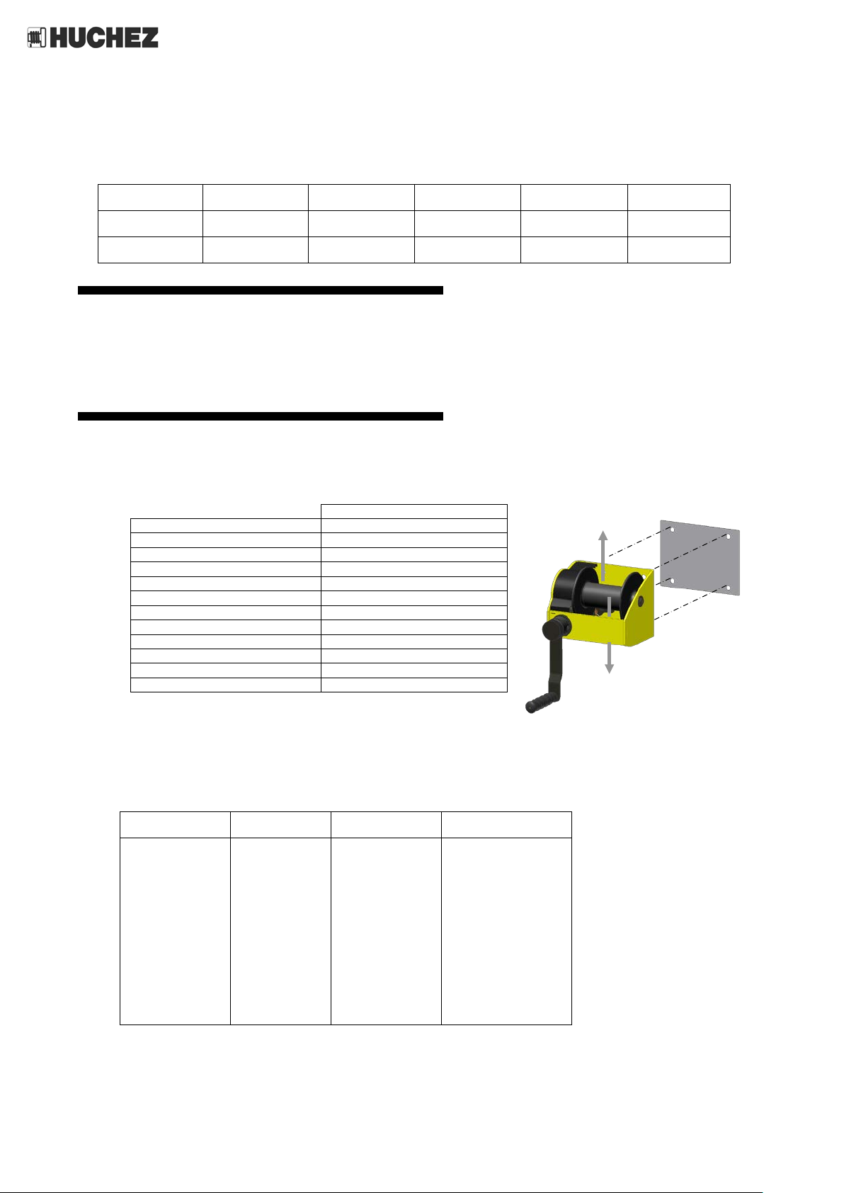
4.1. Fixing
All these screws must be at least 6.8 class.
Calculate and check that the fixing suppor ts hav e eno ugh stre ng th to e asily withstand the loads to be lifted
or pulled.
4.2. Rope
Models
VS 320
VS 500
VS 750
VS 1000
VS 1450
VS 1500
VS 2000
VS 2000
VS 2500
VS 3000
6
7
7
9
10
11.5
12
13
13
15.8
6
18
3
30
5
23
6
17
6
18.5
2
4
1
4
1
3
1
2
1
2
Translation of original manual 5
4.3. Installing the rop e : Strictly observe the rope winding direction. To lift the load, turn the crank clockwise: a click will be heard .
To lower the load, turn the crank in the opposite directio n.
UK
Reproduction prohibited
 Loading...