

Page 1

2.4GHZ RC SERIES 4 CHANNEL
HUBSAN X4
ITEM NO.: H107P
®
Read the User Manual and its
instructions carefully before use!
14+
Page 2

01
TABLE OF CONTENTS
1 FOREWORD
2 SAFETY INSTRUCTIONS
3 PRE-FLIGHT CHECKLIST
4 AIRCRAFT BATTERY & CHARGING
5 THE TRANSMITTER
5.1 GETTING TO KNOW YOUR TRANSMITTER
5.2 TRANSMITTER BATTERY INSTALLATION
6 FLIGHT
6.1 POWER-UP SAFETY PROTOCOL
6.2 HEADLESS MODE
6.3 BASIC FLIGHT OPERATION
6.4 ARMING/DISARMING THE MOTORS
7 ADVANCED FLIGHT SETTINGS
7.1 NORMAL AND EXPERT MODE
7.2 ACRO MODE
8 INSTALLING AND REMOVING PROPELLERS
AIRCRAFT EXPLODED VIEW
H107P FREQUENTLY ASKED QUESTIONS
H107P PARTS & ACCESSORIES
0 2
0 2
0 5
0 6
0 7
0 9
1 0
1 1
1 1
1 3
1 4
1 4
1 6
1 7
1 9
2 2
Page 3

02
1 FOREWORD
Thank you for purchasing a HUBSAN product. The H107P is an easy to fly aircraft
capable of a variety of flight functions. It is equipped with a full-function remote
control. Please read and follow the manual carefully for proper operation and use. Be
sure to keep the manual as important reference for future routine maintenance.
2 SAFETY INSTRUCTIONS
2.1 Precaution
2.2 Warning
2.3 Battery And Charging
This remote control quadcopter is not a toy. Please read this manual carefully before
operating this product. Improper use of the product may result in serious injury. Please
be aware of the environment around you and take appropriate measures to ensure the
safety of yourself and others. We recommend that you make your first flight under the
guidance of an experienced pilot.
This aircraft is made of components that rotate at high speeds, which constitutes a
certain degree of danger. The user must be responsible for any damage and loss
caused by improper use.
Your quadcopter is equipped with a lithium polymer battery (LiPo).
If you plan not to use the product for a week or more, leave the battery at 50% to
preserve the battery's overall lifespan. To do so, charge the battery for half the time
it takes for the battery to fully charge.
Do not fly in crowded places such as people, poles, motor vehicles, roads, or near
airports. Remember that you are responsible for the safety of yourself and others.
Please operate only while alert and sober. Do not operate this product while fatigued
or drunk. This can be dangerous.
WARNING
!
Using the type of wrong battery may cause explosion.
Please dispose of used batteries in accordance with relevant laws and
regulations.
Page 4

03
www.hubsan.com
Do not disassemble or reassemble the battery.
Do not short-circuit the battery.
Do not use or charge near sources of heat.
Do not put the battery in contact with water or any kind of liquid.
Do not puncture or subject the battery to force of any kind.
Do not throw or manhandle the battery.
Never charge a battery that has been damaged, become deformed or
swelled.
Do not solder on or near the battery.
Do not overcharge or over discharge the battery.
Do not reverse charge or reverse the battery polarities.
Do not connect the battery to a car charger/cigarette lighter or any other
kind ofunconventional power source.
!
SAFETY ADVISORY
(LITHIUM-POLYMER/LI-PO BATTERIES)
LiPo batteries are different from conventional batteries in that their
chemical contents are encased in a relatively lightweight foil packaging.
This has the advantage of significantly reducing their weight but it does
make them more susceptible to damage if roughly or inappropriately
handled. As with all batteries, there is a risk of fire or explosion if safety
practices are ignored.
Page 5

This battery is prohibited for non-designated devices.
Do not touch any kind of liquid waste or byproduct from batteries. If skin or
clothes come incontact with these substances, please flush with water!
Do not mix other types of batteries with lithium batteries.
Do not exceed the specified charging time.
Do not place the battery in a microwave or in areas of high pressure.
Do not expose the battery to the sun.
Do not use in environments with high static electricity (64V and above).
Do not use or charge in temperatures below 0 ℃ and above 45 ℃.
If a newly purchased battery is used, leaking, possesses a bad smell or any
other abnormality, return immediately to the vendor.
Keep away from the reach of children.
Use a dedicated battery charger and follow all charging requirements.
Minors who use the battery and its dedicated unit must be supervised by an
adult at all times.
www.hubsan.com
!
SAFETY ADVISORY
(LITHIUM-POLYMER/LI-PO BATTERIES)
04
Page 6

05
2.4 Protection Against Water & Dampness
2.5 Correct Operation
2.6 Pay attention to the rotating blades
For safety reasons, use only Hubsan parts for replacement and repair.
During operation, high speed rotating propeller blades can cause serious bodily
injury or damage to the aircraft. Do not approach the aircraft in flight and do not let
it fly out of your line of sight. If this happens, disarm the motors or power off the
aircraft immediately.
2.7 Avoid Flying Alone
Beginners should avoid flying alone before learning and mastering flying skills. It is
recommended to operate under the guidance of an experienced pilot.
There are many small electrical components in the model. It is important to store/fly
the model in a suitable environment and to avoid placing it around other appliances.
Exposing the model to water or a humid environment may cause failure and damage.
3 PRE-FLIGHT CHECKLIST
• Before operating, fully charge the remote control and the aircraft.
• Before turning on the switch, check that throttle is in its lowest position.
• Check the aircraft chassis and propellers carefully. Broken or failed parts may cause
danger.
• Turn power on the remote control first, then the aircraft. After use, first power off
the aircraft and then the remote control. An incorrect operation sequence may result
in losing control of the aircraft.
Page 7
06
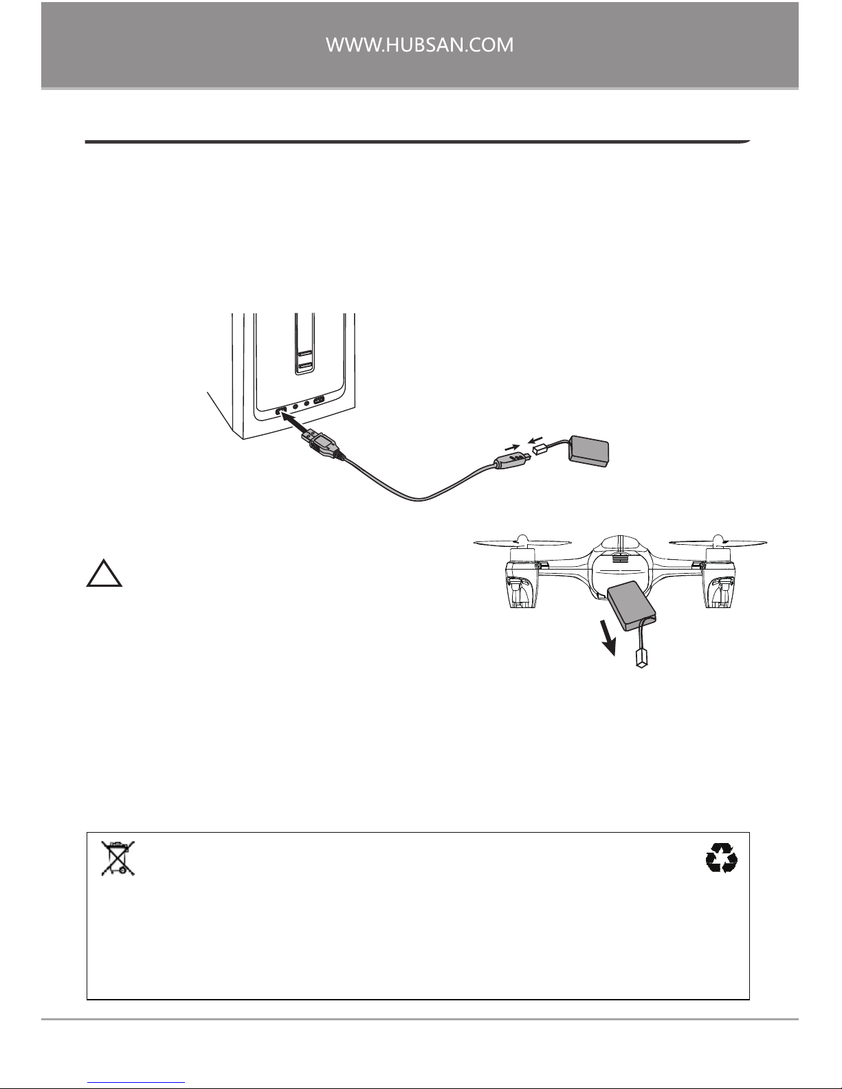
4.1 The 3.7v 520mAh LiPo
Be sure to use the provided Hubsan dedicated charger for charging. Fully charge the
battery before flight. Connect the charger ‘s USB adapter to a PC terminal and then
the battery to the charger. Charging time is approximately 80 minutes; recommended
flight time is 6 minutes.
4.2 Safety Precautions
Lithium batteries do not need to be recharged when in stored short-term. When it is
necessary to store the lithium battery unused for more than 3-6 months, it is
necessary to charge the lithium battery to recover lost voltage.
If your battery is overly discharged, you may not be able to recharge it.
4 AIRCRAFT BATTERY & CHARGING
When charging is complete, disconnect the
charger and battery from power immediately.
!
Lithium battery disposal and recycling
Lithium batteries cannot be disposed with household waste. Please contact your
environmental protection department or waste collection agency or dispose of
the battery at nearest lithium battery recycling center in accordance with local
regulations.
3.7V 520mAh
3.7V 520mAh
Page 8
07
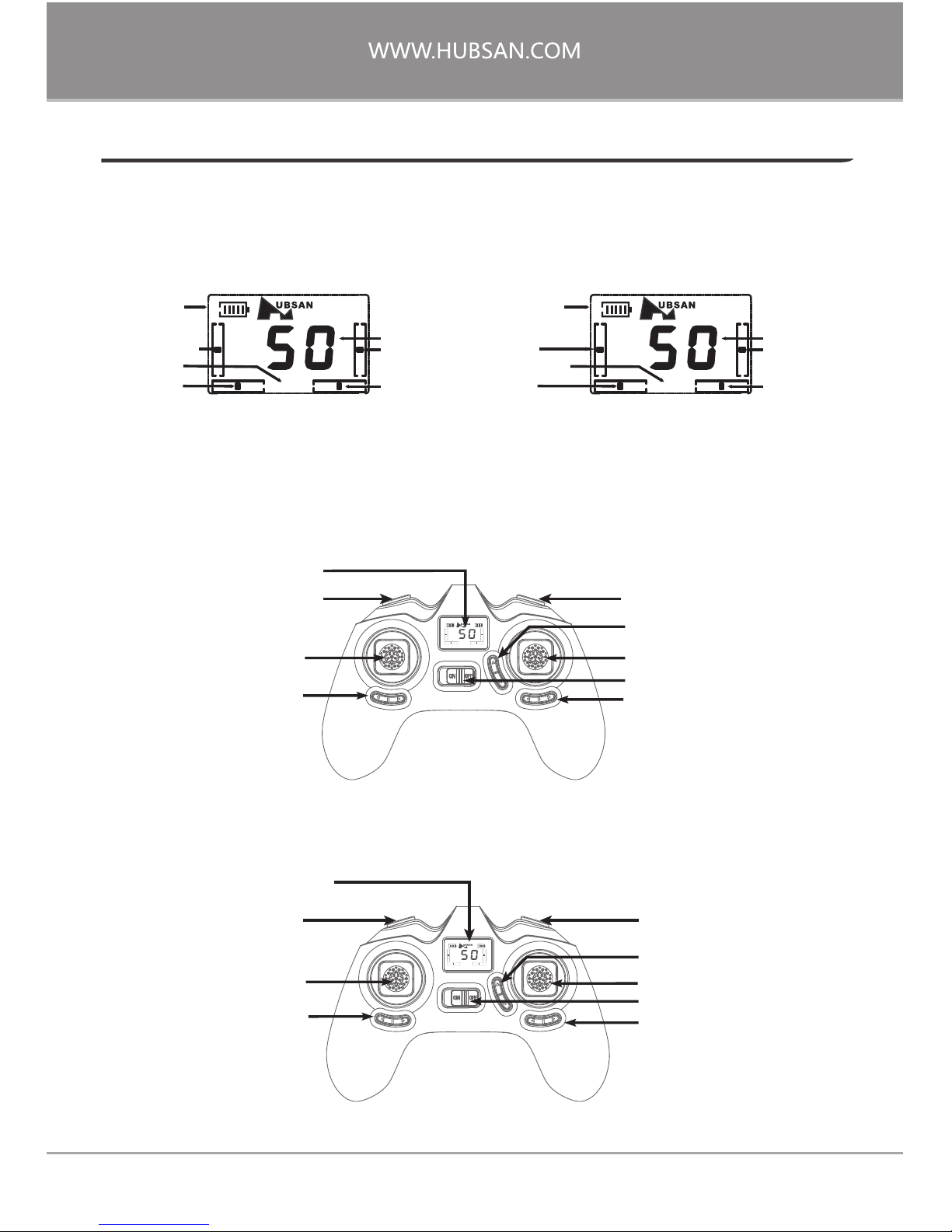
5.1 Getting To Know Your Transmitter
Main Interface
5 THE TRANSMITTER
Mode 1 (Japanese Hand)
Mode 2 (American Hand)
T
X
M2
Expert
Transmitter
power level
Transmitter
power level
Rudder channel
Elevator channel
Joystick power
Throttle channel
Aileron channel
Joystick power
Throttle
channel
Aileron channel
Expert Mode
Rudder
channel
Elevator channel
Expert Mode
T
X
M1
Expert
Transmitter
Mode 1 (Japanese Hand)
Mode 2 (American Hand)
TXR
X
M1 M2
Expert
(1)Throttle/Aileron joystick(2)Elevator/Yaw joystick
8 Yaw trim
7 Elevator trim
6 Aileron trim
9 Screen
3 No Function
4 No Function
5 Power
TXR
X
M1 M2
Expert
8 Yaw trim
7 Elevator trim
9 Screen
3 No Function
4 No Function
5 Power
6 Aileron trim
1 Throttle/Yaw joystick
2 Elevator/Aileron joystick
Page 9

08
Transmitter Key Functions
Throttle/Aileron stick
S/N KEY/SWITCH FUNCTION
Throttle/Rudder stick
1
Elevator/Aileron stick
2
3
No Function \
\
4
No Function
5
Power
Push left/ON to turn on the transmitter. Push right/OFF to turn off.
6
Aileron trim
Elevator/Rudder stick
(2)
(1)
Use the Aileron trim to adjust for left (trim the channel right)
horizontal drift and right horizontal drift (trim the channel left).
7
8
9
Elevator trim
Rudder trim
Screen
Displays the aircraft's current status.
Use the Elevator trim to adjust for forward and backward drift.
Use the Rudder trim to adjust for counterclockwise and clockwise
rotation/yaw drift.
Push the stick forward or backward and the quadcopter will
ascend or descend (respectively). Push the stick left or right and
the quadcopter will rotate counterclockwise or clockwise (respectively).
Push the stick forward or backward and the quadcopter will fly
forwards or backwards (respectively). Push the stick left or right
and the quadcopter will fly left or right (respectively).
Push the stick forward or backward and the quadcopter will
ascend or descend (respectively). Push the stick left or right and
the quadcopter will fly left or right (respectively).
Push the stick forward or backward and the quadcopter will fly
forwards or backwards (respectively). Push the stick left or right
and the quadcopter will rotate counterclockwise or clockwise
(respectively).
Page 10

09
5.2 Transmitter Battery Installation
Environmental Impact
Old appliances cannot be processed together with ordinary garbage. Please
dispose of them separately. Usage of public waste collection points is
typically free and owners of old appliances have the obligation and
responsibility to send used electrical appliances to these waste collection
point for disposal. Through our personal efforts, we can repeatedly use
valuable raw materials and mitigate the uncontrolled release of harmful
substances.
!
Do not mix new and old batteries.
Do not cross-use different types of batteries at the same time.
Do not charge with non-rechargeable batteries.
Open the battery
compartment.
Push
Install 4 AAA batteries
(be sure to match
polarities correctly).
Slide the battery door
back onto the compartment.
Push
Page 11

10
6.1 Power-Up Safety Protocol
6 FLIGHT
Your aircraft has a power-up safety protocol. When both your remote control and the
aircraft are powered on, the aircraft motors will not start up unless an arming signal is
detected.
The transmitter will beep and the aircraft's LEDs stop blinking to indicate that two are
properly bound.
Low battery alarm: When the aircraft battery is low, the aircraft's two red LEDs flash
simultaneously. The aircraft automatically descends from a height of 5 meters or less.
6.1.3 Aircraft Status Indicator
6.1.2 Push the battery into the battery compartment as shown in the figure, connect
the power adapters, coil the power cord into the aircraft and close the battery
compartment.
6.1.1 Power on the remote and watch the aircraft
parameters appear on the remote control screen. Please do
not touch any joysticks or buttons before the transmitter
and the aircraft finish pairing, otherwise the aircraft may roll
over.
Page 12

6.2 Headless Mode
To access Headless Mode, *first* make sure that you “set” a forward direction. Say,
you'd like to consider due North as your “forward” direction. Have the drone's head
facing North- then and only then, initiate Headless mode. During Headless Mode,
the aircraft's blue LEDs will be flashing together simultaneously. The "Headless"
symbol will also come on-screen.
Mode 2
(American Hand)
Mode 1
(Japanese Hand)
T
X
M1 M2
11
Press down onto the throttle joystick (you should feel and hear a click) to enter or exit
Headless Mode.
Short press the throttle joystick to enter Headless Mode and the “ ”symbol will
appear on the remote control screen.
Short press the throttle joystick to exit Headless Mode and the “ ”symbol will
disappear from the remote control screen.
The remote control is by default set to Mode 2 in factory.This manual will introduce
flight operations in Mode 2.
-Transmitter joysticks are self-centering and spring loaded: the joysticks will automatically center themselves
-Joystick sensitivity: dependent how much and how forcefully each joystick is pulled
or pushed away from center point
6.3 Basic Flight Operation
Page 13

REMOTE CONTROL
AIRCRAFT
The throttle is used to control the ascent and descent of the aircraft. Push the throttle up and the
aircraft ascends. Pull the throttle back and the aircraft descends. When the joystick is centered
(unmoving), the aircraft will hold its altitude in the air. The throttle must be pushed upwards beyond
center point for the aircraft to completely takeoff from the ground. The harder the throttle is
pushed, the faster the aircraft will ascend. Please push the throttle slowly for a gradual lift and to
prevent the aircraft from ascending erratically.
The rudder is used to control the aircraft's rotations. Push the joystick to the left and the aircraft
rotates counterclockwise. Push the joystick to the right and the aircraft rotates clockwise. When the
joystick is centered (unmoving), the angular velocity of the aircraft is "0" and the aircraft will not
turn. How hard the rudder is pushed will determine the angular velocity of the aircraft's rotation.
The harder the rudder is pushed, the faster the aircraft rotates.
The elevator controls the aircraft's forward and backward movement. Push the joystick forward and
the aircraft will tilt and fly forward. Pull the joystick back and the aircraft will tilt and fly backwards.
When the joystick is centered (unmoving), the aircraft will hold its altitude in the air. How hard the
elevator is pushed will determine the degree of the aircraft's tilt and therefore the velocity of its
forward and backward movement. The harder the elevator is pushed, the greater the aircraft's tilt
angle and flight speed either forwards or backwards.
Mode 2 (American Hand)
Mode 2 (American Hand)
TXR
X
M1 M2
Expert
Mode 1 (Japanese Hand)
Mode 1 (Japanese Hand)
Mode 2 (American Hand) Mode 1 (Japanese Hand)
TXR
X
M1 M2
Expert
TXR
X
M1 M2
Expert
TXR
X
M1 M2
Expert
TXR
X
M1 M2
Expert
TXR
X
M1 M2
Expert
TXR
X
M1 M2
Expert
TXR
X
M1 M2
Expert
Ascend
Descend
Counterclockwise Clockwise
Forward
Backward
12
Page 14

!
Note: Pilots may also disarm the aircraft motors by holding the throttle in its lowest
position after the aircraft has completed its descent on the ground.
6.4 Arming/Disarming the Motors
Arming/starting motors
Simultaneously pull the transmitter joysticks
diagonally down-out to arm the motors
(as shown in the side figure).
Disarming/stopping motors
Simultaneously pull the transmitter joysticks
diagonally down-out to disarm the motors
(as shown in the side figure).
Please disarm the motors first before turning off the remote. If you turn off the
remote first, the aircraft will attempt to perform a landing.
13
REMOTE CONTROL
AIRCRAFT
The aileron controls the aircraft's left and right movement. Push the joystick to the left and the
aircraft will tilt and fly leftwards. Pull the joystick to the right and the aircraft will tilt and fly rightwards. When the joystick is centered (unmoving), the aircraft will hold its altitude in the air. How
hard the aileron is pushed will determine the degree of the aircraft's tilt and therefore the velocity
of its left and right movement. The harder the aileron is pushed, the greater the aircraft's tilt angle
and flight speed either leftwards or rightwards.
TXR
X
M1 M2
Expert
TXR
X
M1 M2
Expert
Left Right
Mode 2 (American Hand) Mode 1 (Japanese Hand)
NOTE: When the aircraft's head faces the pilot
during flight, all control inputs from the joysticks will
be backwards.
Page 15

7 ADVANCED FLIGHT SETTINGS
14
Press down on and hold the throttle stick to enter Acro Mode. The remote control
will "beep" to indicate that the aircraft is ready to do flips and rolls.
7.2 Acro Mode
7.1 Normal and Expert Mode
Normal Mode
Expert Mode
T
X
M1 M2
T
X
M1 M2
Expert
Whenever it is powered on, this aircraft will default to "Normal Mode". Although this
aircraft responds quickly in "Normal Mode", it is even more fragile in "Expert Mode".
When the aircraft has entered "Expert Mode", the remote screen will display "Expert".
Operation: Short press the non-throttle joystick to switch between "Normal Mode"
and "Expert Mode". Entering Expert Mode will cause the transmitter to beep twice;
exiting Expert Mode will result in one beep.
Page 16

TXR
X
M1 M2
Expert
TXR
X
M1 M2
Expert
TXR
X
M1 M2
Expert
TXR
X
M1 M2
Expert
TXR
X
M1 M2
Expert
www.hubsan.com
Short press on the throttle (you should feel and hear a click) and push the aileron
stick forward. The aircraft will perform a front flip.
7.2.1 Front flip
Short press on the throttle (you should feel and hear a click) and push the aileron
stick right. The aircraft will perform a right roll.
7.2.4 Right roll
7.2.2 Back flip
Short press on the throttle (you should feel and hear a click) and push the aileron
stick left. The aircraft will perform a left roll.
7.2.3 Left roll
Mode 1
(American Hand)
Mode 2
(Japanese Hand)
Mode 1
(American Hand)
Mode 2
(Japanese Hand)
Mode 1
(American Hand)
Mode 2
(Japanese Hand)
Mode 1
(American Hand)
Mode 2
(Japanese Hand)
15
TXR
X
M1 M2
Expert
TXR
X
M1 M2
Expert
Short press on the throttle (you should feel and hear a click) and push the aileron
stick backward. The aircraft will perform a back flip.
Page 17

Before installing propellers for the first time, please check that each Propeller A is
matched with motor A and each Propeller B is matched with motor B. If propellers
are improperly paired with the wrong motors, the aircraft will not be able to takeoff
or fly properly and will most likely crash.
8 INSTALLING AND REMOVING PROPELLERS
A
A
FRONT
B
B
A
A
B
B
16
Removal: Hold the propeller and insert
the U-shaped wrench right under the
propeller hub. Press the wrench upward
and the propeller will come off.
Installation: Hold the new propeller by its
hub and press it firmly onto the motor
shaft.
Page 18

AIRCRAFT EXPLODED VIEW
17
2
3
4
5
6
6
6
6
1
7
8
8
9
9
11
10
13
12
16
14
15
14
14
14
18
18
17
17
Page 19

1
Body Shell (Top)
9
Motor A
10
Propeller A (Black)
11
Propeller B (Black)
12
Propeller A (White)
13
Propeller B (White)
14
Screw
15
16
2
Body Shell (Bottom)
3
Battery Compartment
4
Battery Compartment Cover
5
Battery
6
Motor Cover
7
PCB Motherboard
8
Motor B
No.
Part Name
Qty
No.
Part Name
Qty
1
1
1
1
1
4
1
2
2
1
1
1
1
1
8
4
Screw
Propeller Guard
18
Page 20

H107P FREQUENTLY ASKED QUESTIONS
1. Aircraft and remote control are not pairing.
Restart the aircraft and its remote. Power on the aircraft first, followed by the
transmitter.
2. The transmitter powers on, then shuts off immediately after.
The remote control battery voltage is too low. Check that the batteries is installed
correctly. If needed, please replace with fresh AAA batteries.
4. Aircraft is incapable of rolling or flipping.
3. The propellers aren't spinning, or are spinning very slowly.
(1) Use Expert Mode if not already active.
(2) The battery is too low on power.
(1) Aircraft battery voltage is too low.
(2) Aircraft and transmitter need a rebind.
(3) Pull the throttle to its lowest position and wait 3 seconds before attempting to
fly again.
(4) Check whether the propellers are stuck too far down the motor shaft.
Make sure that when you are pressing on the non-throttle stick to enter and exit
Expert Mode, that the press is short and gentle, but firm.
5. Aircraft shakes and/or is very noisy during flight.
Answer: Check that motors, aircraft body and propellers are installed correctly.
Also see if the propellers are deformed or damaged.
6. Switching between Expert and Normal Mode is not consistent or smooth.
(1) Check that all propellers are correctly installed. Please install propellers correctly as
shown below if there are some matched with incorrect motors.
7. The propellers are spinning, but the aircraft will not takeoff
19
Page 21

(2) Motor(s) are/is installed incorrectly. Check to make sure that each motor is
installed correctly: each motor has two differently colored motor wires. Please check
the figure on how to redo incorrectly installed motors.
Top View
9. How to remove and install LEDs
Disassembly: Remove body screws; detach the body shell halves and all 4 feet.
Desolder the selected LED's red and yellow wires from the PCB.
Installation: Solder the red wire of the selected to the positive pole (+), the yellow
wire to the negative pole (-). Press the LED wires into their designated grooves in the
aircraft arms; do the same for the motor wires. Screw the body shell back together
and reinstall the aircraft feet. You can identify the color of each LED based on the
color of the tube underneath the lamp shade: the blue LED's tubing is blue and the
red LED's tubing is red.
White
Black
White
Black
Black
Red
Blue
Red
LED
LED
LED
M M
M M
LED
A
A
A
A
B
B
B
B
LED
LED
Red Wire
Yellow Wire
LED
LED
1. First align, press the LED wires into
their designated grooves in the
aircraft arms. Make sure that the
black casing underneath the LED's
lamp head faces outward.
2. Put the LED lamp head through its
designated cavity and carefully thread
the LED wire through the grooves in
the selected LED's foot.
Installation Complete
20
Page 22

(2) If the aircraft still drifts a lot in a specific direction, add a few pieces of paper (the
worse the drifting is, the more sheets you will need) under the foot of the aircraft
(that points in the drift-affected direction).
21
10. Motor(s) does not turn after a fall or crash.
Check for and remove any foreign material on the motor or motor shaft. If a propeller
or propellers still does not turn, replace the motor. Check to see if a propeller is stuck
on its motor shaft as well.
11. One or more motors does not function.
12. The aircraft consistently drifts in a specific direction.
(1) Rotate the affected motor propeller to check whether it's pressed too far down
onto the motor.
(2) Check to see if any motor wires are detached from the motherboard. If so, please
re-solder the motor wire(s) back onto their designated points.
(3) Replace the motor.
(1) Place the aircraft on a completely horizontal and unmoving surface. Hold the
yaw/rudder stick to the most down-right diagonal corner of its socket. Rapidly wiggle
the aileron stick left and right continuously until all 4 LEDs flash simultaneously.
Calibration is complete when all 4 LED indicators stop flashing. It is recommended
that users wait for 15-20 seconds after the calibration is completed before flying
again.
MODE1 MODE2
Page 23

H107P PARTS & ACCESSORIES
CANOPY MOTOR SLEEVE
BATTERY
COMPARTMENT
COVER
PROPELLER GUARD
SCREWDRIVER
CRASH KIT
H107P-04 H107-A02
PROPELLERS
H107P-07
H107P-10
MOTORSBODY SHELL
H107P-12
H107P-09
BATTERY
H107-A06
USB CHARGER
PCB MOTHERBOARD
H107P-16
SCREW SET
H107P-14
TRANSMITTER
H107-A13
T-SHIRT
H107-A11
WRENCH
H107P-02
BLUE LED
H107P-06
H107P-05 H107P-11
H107P-01
RED LED
H107P-03
H107P-15
22
Page 24

This manual is subject to change without notice.
WWW.HUBSAN.COM
Version 2.0
 Loading...