

English
Operating and Assembly Instructions
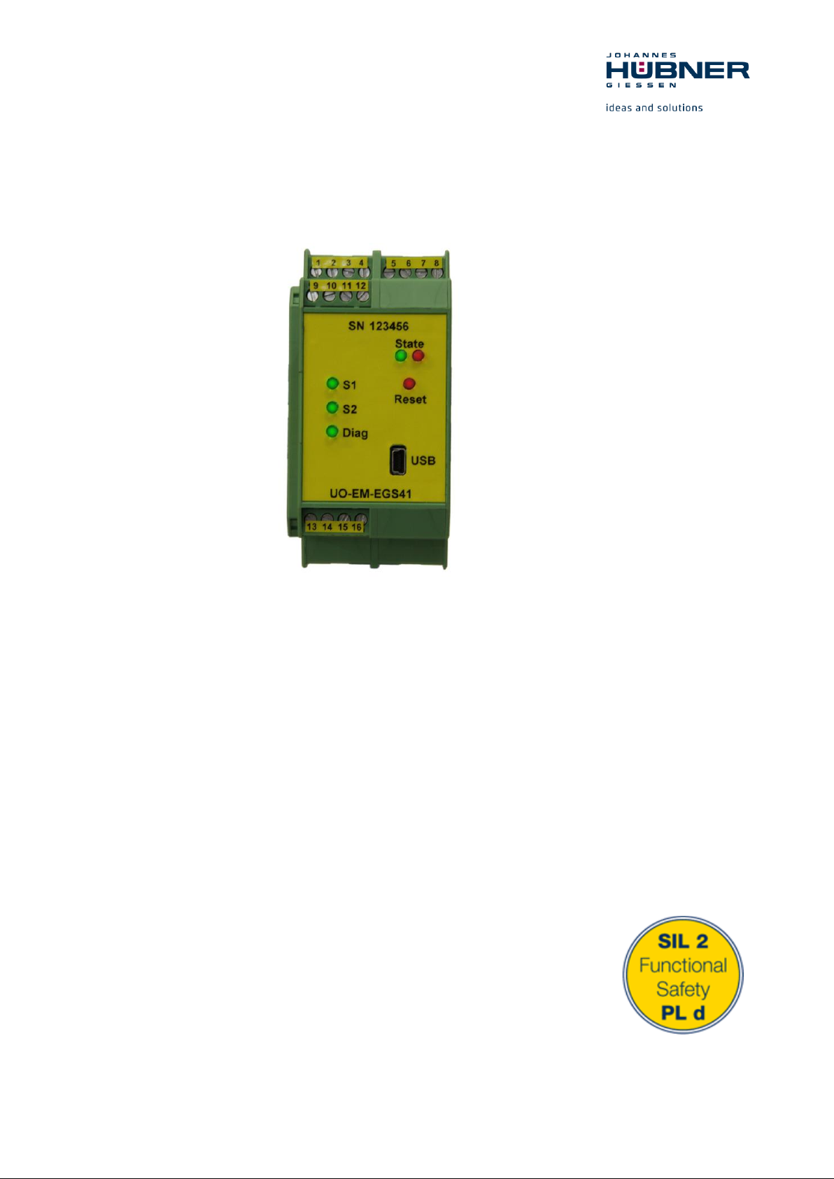
Electronic function module UO-EM-
EGS41
Evaluation to U-ONE® - electronic overspeed switch
certificated according EN 61508 SIL2 and DIN EN ISO 13849-1 PL d
Translation of the original
operating and assembly instructions October 2018
ID 74481
Universal encoder system U-ONE
®
Electronic function module UO-EM-EGS41
2
Read the Operating and Assembly Instructions prior to assembly,
starting installation and handling!
Keep for future reference!

Universal encoder system U-ONE
®
Electronic function module UO-EM-EGS41
3
US41_Manual_En.doc
Build:
31018
Trademark
U-ONE is a registered trademark of Johannes Hubner Fabrik elektrischer Maschinen GmbH.
Windows® is a registered trademark of Microsoft Corporation in the United States and other countries.
Viton® is a registered trademark by Du Pont.
Loctite® is a registered trademark from Henkel AG & Co. KGaA, Düsseldorf.
All other brand names and product names are trademarks or registered trademarks of their respective
owner.
Protected trademarks bearing a ™ or
However, the statutory rights of the respective owners remain unaffected.
Manufacturer / publisher
Johannes Hubner
Fabrik elektrischer Maschinen GmbH
Siemensstraße 7
35394 Giessen
Germany
Phone: +49 641 / 7969-0
Fax: +49 641 / 73645
E-Mail: info@huebner-giessen.com
www.huebner-giessen.com
Headquarters: Giessen
Court of registration: Giessen
Commercial register number: HRB 126
The manual has been drawn up with the utmost care and attention. Nevertheless, we cannot exclude
the possibility of errors in form and content. It is strictly forbidden to reproduce this publication or parts
of this publication in any form or by any means without the prior written permission of
Johannes Hubner Fabrik elektrischer Maschinen GmbH.
Subject to errors and changes due to technical improvements.
Copyright © Johannes Hubner Fabrik elektrischer Maschinen GmbH.
All rights reserved.
®
symbol are not always depicted as such in the manual.

Universal encoder system U-ONE
®
Electronic function module UO-EM-EGS41
4
Directory
1 General ............................................................................................................................ 5
1.1 Information about the operating and assembly instructions ....................................................... 5
1.2 Scope of supply .......................................................................................................................... 5
1.3 Explanation of symbols ............................................................................................................... 5
1.4 Disclaimer ................................................................................................................................... 6
1.5 Copyright..................................................................................................................................... 6
1.6 Guarantee terms ......................................................................................................................... 6
1.7 Customer service ........................................................................................................................ 6
2 Safety ............................................................................................................................... 6
2.1 Responsibility of the owner ......................................................................................................... 6
2.2 Personnel .................................................................................................................................... 7
2.3 Special dangers .......................................................................................................................... 7
3 Technical Data ................................................................................................................ 8
3.1 Construction and function ........................................................................................................... 8
3.2 Short description ......................................................................................................................... 8
3.3 Overspeed switch-off .................................................................................................................. 8
3.4 Reset input .................................................................................................................................. 9
3.5 Other functions ........................................................................................................................... 9
3.6 Type plate /connection diagram ............................................................................................... 10
3.7 Connected loads environment .................................................................................................. 10
3.8 Connectors and Indicators ........................................................................................................ 11
3.9 Mounting the module ................................................................................................................ 11
3.10 Dimension drawing ................................................................................................................... 11
4 Functional safety ...........................................................................................................12
4.1 Characteristic safety values ...................................................................................................... 12
4.2 Timing ....................................................................................................................................... 13
4.3 Switching deviation ................................................................................................................... 13
4.4 Proper use ................................................................................................................................ 14
4.5 Improper use ............................................................................................................................. 14
4.6 Notes on configuration .............................................................................................................. 14
4.7 Switch delay .............................................................................................................................. 14
4.8 Slip angle detection .................................................................................................................. 14
4.9 Diagnostic output ...................................................................................................................... 14
4.10 Faults table ............................................................................................................................... 15
4.11 Error table ................................................................................................................................. 15
5 Transport, packaging and storage ...............................................................................16
5.1 Safety information concerning transport ................................................................................... 16
5.2 Goods inward inspection .......................................................................................................... 16
5.3 Packaging (disposal) ................................................................................................................ 16
5.4 Storing packages (devices) ...................................................................................................... 16
5.5 Returning devices (repairs/goodwill/warranty).......................................................................... 17
5.6 Disposal .................................................................................................................................... 17
6 Certificate .......................................................................................................................18
Universal encoder system U-ONE
®
Electronic function module UO-EM-EGS41
5
1 General
1.1 Information about the operating and assembly instructions
These operating and assembly instructions provide important instructions for working with the device.
They must be carefully read prior to starting all tasks, and the instructions contained herein must be
followed.
In addition, applicable local regulations for the prevention of industrial accidents and general safety
regulations must be complied with.
For other, non SIL certified electronic function modules please refer to the separate Operating and
Installation Instructions.
1.2 Scope of supply
The scope of supply of the electronic function module overspeed switch UO-EM-EGS41 includes the
Operating and Installation Instructions (with SIL safety instructions), the programming software
EGS41Pro (on CD) and the programming cable.
The Operating and Installation Instructions for the electronic function module is also included on the
supplied CD.
1.3 Explanation of symbols
Warnings are indicated by symbols in these operating and assembly instructions. The warnings are
introduced by signal words that express the scope of the hazard.
The warnings must be strictly heeded; you must act prudently to prevent accidents, personal injury,
and property damage.
WARNING!
Indicates a possibly dangerous situation that can result in death or serious injury if it
is not avoided.
CAUTION!
Indicates a possibly dangerous situation that can result in minor injury if it is not
avoided.
CAUTION!
Indicates a possibly dangerous situation that can result in material damage if it is not
avoided.
NOTES!
Indicates useful tips and recommendations as well as information for efficient and
trouble-free operation.
NOTES!
Do not use a hammer or similar tool when installing the device due to the risk of
damage occurring to the bearings or coupling!
DANGER!
Life-threatening danger due to electric shock!
Indicates a life-threatening situation due to electric shock. If the safety instructions
are not complied with there is danger of serious injury or death. The work that must
be executed should only be performed by a qualified electrician.
Universal encoder system U-ONE
®
Electronic function module UO-EM-EGS41
6
1.4 Disclaimer
All information and instructions in these operating and assembly instructions have been provided under due consideration of applicable guidelines, as well as our many years of experience.
The manufacturer assumes no liability for damages due to:
Failure to follow the instructions in the operating and assembly instructions
Non-intended use
Deployment of untrained personnel
Opening of the device or conversions of the device
In all other aspects the obligations agreed in the delivery contract as well as the delivery conditions of
the manufacturer apply.
1.5 Copyright
NOTE!
Content information, text, drawings, graphics, and other representations are protected
by copyright and are subject to commercial property rights.
It is strictly forbidden to make copies of any kind or by any means for any purpose
other than in conjunction with using the device without the prior written agreement of
the manufacturer. Any copyright infringements will be prosecuted.
1.6 Guarantee terms
The guarantee terms are provided in the manufacturer´s terms and conditions.
1.7 Customer service
For technical information personnel is available that can be reached per telephone, fax or email. See
manufacturer´s address on page 2.
2 Safety
DANGER!
This section provides an overview of all the important safety aspects that ensure protection of personnel, as well as safe and trouble-free device operation.
If these safety instructions are not complied with significant hazard can occur.
2.1 Responsibility of the owner
The device is used in commercial applications. Consequently the owner of the device is subject to the
legal occupational safety obligations, and subject to the safety, accident prevention, and environmental protection regulations that are applicable for the devices area of implementation.

Universal encoder system U-ONE
®
Electronic function module UO-EM-EGS41
7
2.2 Personnel
Qualified personnel only are permitted to install, mount, program, commission, operate, maintain and
take out of service the devices.
Qualified personnel are people who have received
training to qualify as an electrician or
instructions from qualified trades personnel
entitling them to work with and on devices, systems, machinery and plant in accordance with generally
accepted standards and safety engineering guidelines.
In addition, the owner is obliged to deploy only personnel who
are familiar with the fundamental regulations covering work safety and accident prevention,
have read and understood the chapter "Safety" in these Operating and Installation
Instructions,
and are familiar with the basic and specialist standards that apply to the specific application.
2.3 Special dangers
Residual risks that have been determined based on a risk analysis are cited below.
DANGER!
Life-threatening danger due to electrical shock!
There is an imminent life-threatening hazard if live parts are touched. Damage to insulation or to specific components can pose a life-threatening hazard.
Therefore:
Immediately switch off the device and have it repaired if there is damage to the insulation of the power supply.
De-energize the electrical equipment and ensure that all components are connected
for all tasks on the electrical equipment.
Keep moisture away from live parts. Moisture can cause short circuits.
DANGER!
Life-threatening danger if restarted without authorization!
When correcting faults there is danger of the power supply being switched on without authorization.
This poses a life-threatening hazard for persons in the danger zone.
Therefore:
Prior to starting work, switch off the system and safeguard it from being switched on
again.

Universal encoder system U-ONE
®
Electronic function module UO-EM-EGS41
8
3 Technical Data
3.1 Construction and function
Block diagram:
3.2 Short description
The U-ONE universal encoder system including the basic device UOM(H) 41L-1212 and the electronic
function modules UO-EM-D41 and UO-EM-EGS41 is an overspeed switch (certified to EN 61508 SIL2
and EN 13849-1 PLd).
The function module is configured using a PC running a Windows® operating system (XP, Vista and
7) in conjunction with the programming software EGS41Pro included in the scope of supply. The physical interface is USB.
The overspeed switches S1 and S2 are switched according to the set speed parameters.
The switches S1 terminal 9/10 and S2 terminal 13/14 are envisaged for safety-relevant switching. A
separate diagnostic switch is connected in series. An auxiliary contact is also available for each respective switch S1 (terminal 11/12) and S2 (terminal 15/16).
The outputs of the switches are electrically isolated from the electronics and the PC interface.
3.3 Overspeed switch-off
The incremental signal is utilized to determine the speed. The switch opens reliably if the speed exceeds the user-defined switching point

Universal encoder system U-ONE
®
Electronic function module UO-EM-EGS41
9
The device is equipped with a safety relay with positively driven
contacts for each switching output. That facilitates 2-channel evaluation
of the switching status with line monitoring by a downstream control.
The module incorporates 2 identical switching channels (S1 and S2).
Green LEDs indicate the switching status of the safety switches (lit LED
= switch closed).
A separate diagnostics switch (Diag) closes when no errors are diagnosed. This is also indicated on the front of the module by a green LED.
If an error is established the switch opens and a red LED lights up.
3.4 Reset input
The reset input is electrically isolated and triggers a module restart (hardware reset) when a DC voltage (12...30 VDC) is applied. The module performs an complete self-test. An established error is reset.
3.5 Other functions
The following additional, non safety-relevant functions are available:
Adjustable release point:
The user is able to select the release point (hysteresis) as required across the entire operating
range.
Restriction: the difference between the speed of the release point and the switching point must be
at least 10%.
Underspeed
To facilitate underspeed switch-off it is possible to activate a further switching point (underspeed
switch-off). The switch opens if the speed falls below the set switching point (see configuration
Guide).
Slip detection
The slip detection function closes a switch if the set slip angle is exceeded
(see configuration Guide).
Rotation direction dependent switching
It is possible to select a variety of switching speeds, depending on the direction of rotation. This
function can be combined with all other functions (see configuration Guide).
Switch delay
Briefly overshooting the switching speed (1 ms...300 ms) will not trigger overspeed switch-off (see
configuration Guide).
Universal encoder system U-ONE
®
Electronic function module UO-EM-EGS41
10
Description
Worth
Supply voltage
Supply via bus connections (12 … 30 V DC)
Power consumption
max. 2 W
Connection
COMBICON®-terminal strips
Switching outputs S1/2
Switching output Diag
Switching power
(max. switching cycles: approx. 2 x 10⁶)
5 … 230V AC 5 … 500 mA
5 … 30V DC 5 … 500 mA
230V DC 5 … 150 mA
Reset input
potential free, reset voltage 12 … 30 V DC / ca. 7 mA
Programmable switching speeds
0,5 … 2700 rpm
Switching differential
(see. chapter. 4.3)
Measuring angle approx.1°
Accuracy: 2%
Switching time TSw: < 20 ms
Programming interface
USB
Connecting diagram
PN169-400
Device temperature range
-25 … + 70 °C
Degree of protection
IP20
Relays with forcibly guided contacts
max. 230V AC/DC 5 … 500mA
Relay contact
max. 230V AC/DC 5 … 500mA
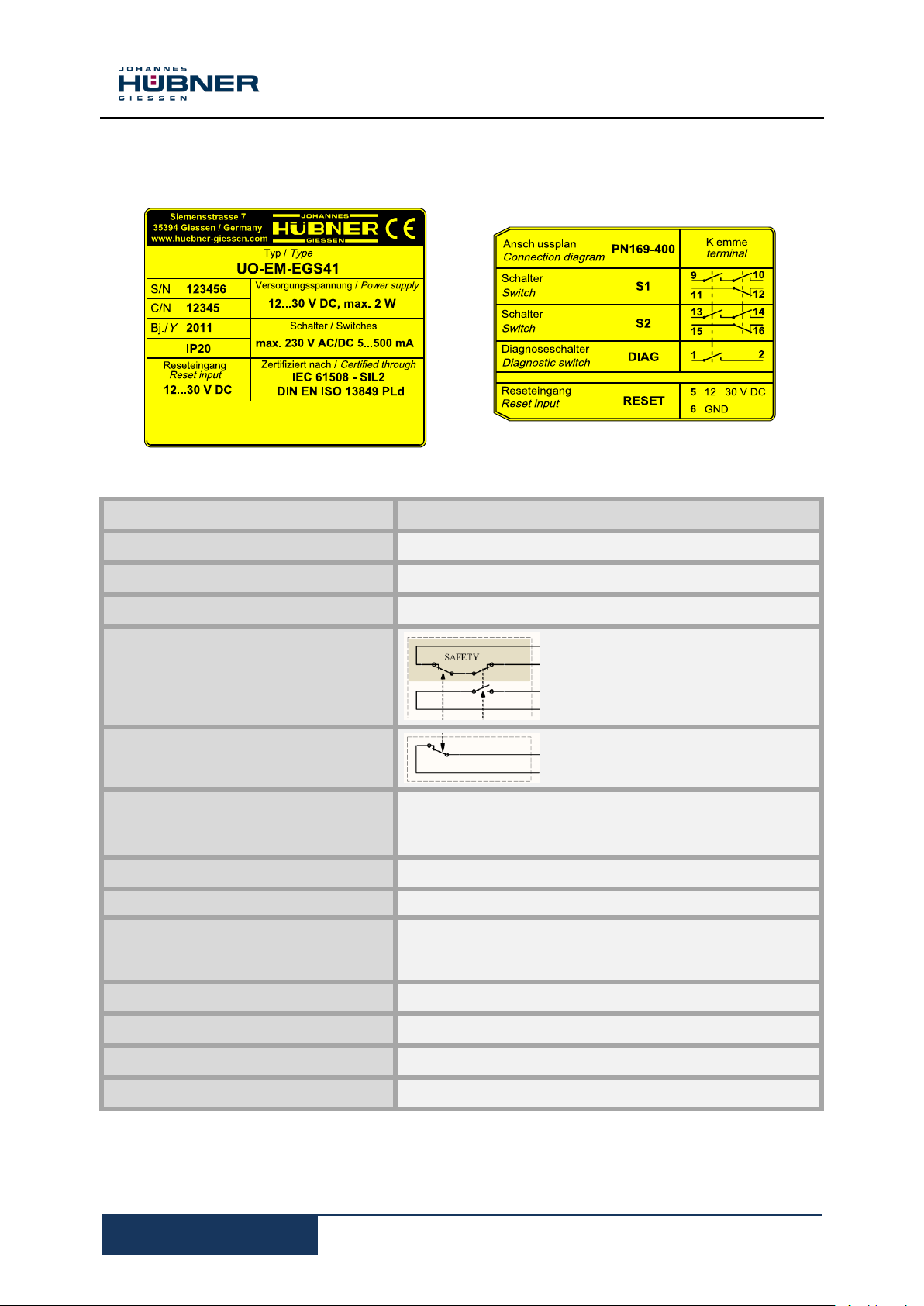
3.6 Type plate /connection diagram
3.7 Connected loads environment
Install a back-up fuse (2A) to protect the relay contacts against overcurrents.

Universal encoder system U-ONE
®
Electronic function module UO-EM-EGS41
11
Indicators
S1, S2, Diag
LEDs light up when
switches are closed
State
Green LED
Lit: Operational
Flashes 1x Absolute signal
not detected (FOC 2)
Flashes 2x Speed signal
not detected (FOC 1)
Red LED lit: Error condition
Reset
Red LED lit: Reset condition
A = 114,50 mm
B = 45 mm
3.8 Connectors and Indicators
3.9 Mounting the module
Snap the modules onto the top-hat rail and slide together.
ATTENTION!
Ensure you do not damage the connectors when you snap the modules onto the rail
and push them together!
Ensure the modules contact reliably when joining them together on the top-hat mounting rail.
Fit the supplied shrouding covers to both ends of the mounted terminals.
Follow the connection diagram!
3.10 Dimension drawing

Universal encoder system U-ONE
®
Electronic function module UO-EM-EGS41
12
Characteristic safety values
Safety class / standard
SIL2 to EN 61508
Performance level 'd' to EN ISO 13849-1
Category 2
System structure
1 channel with diagnostics (1oo1D)
Device type
Type B (complex components)
Hardware fault tolerance (HFT)
0
Type of operating mode
'High demand' to EN 61508
(high demand rate)
Probability of a dangerous failure per
hour (PFHd)
1,44 x 10⁻⁷ [1/h]
Failure rate:
safe detected (λSD)
safe undetected (λSU)
Dangerous detected (λDD)
Dangerous undetected (λDU)
λ
SD
: 8,40 x 10⁻⁷ [1/h]
λ
SU
: 2,22 x 10⁻⁷ [1/h]
λ
DD
: 1,13 x 10⁻⁶ [1/h]
λ
DU
: 1,44 x 10⁻⁷ [1/h]
Mean time to a dangerous failure
(MTTFd)
89.9 years (high)
Diagnostic coverage on average
(DC
AVG
)
medium
Proportion of safe failure fraction (SFF)
93,8%
Service life or
proof test interval to EN 61508
10 years
Thereafter the components must be replaced with
new components
Safe state
Switch S1 (terminals 9 / 10) open
Switch S2 (terminals 13 / 14) open
Diagnostic switch open.
Safety function
Safe overspeed switch-off switch S1 (terminals 9 /
10) and switch S2 (terminals 13 / 14).
4 Functional safety
4.1 Characteristic safety values
The details below refer to the overall system consisting of:
Electronic function module UO-EM-EGS41 (overspeed switch)

Universal encoder system U-ONE
®
Electronic function module UO-EM-EGS41
13
min/1
1000
)(
0
DSmess
Fehler
TTT
nnn
n0: Programmed switching
speed [rpm]
: Acceleration
s
min/1
T
D:
Adjustable switch delay [s]
T
Sys
: System time [s]
n
error
: 0.02 (2%)
ms
n
T
mess
0
6
1000
4.2 Timing
Chapter 7.4.3.2.5 of
EN 61508-2 should also be taken into consideration with regard to the process safety time of the application.
Power-on time T
After the power supply is turned on initial internal diagnostic checks are carried out before the device
is ready for operations.
The power-on time is approx. 1.6 s.
Diagnostic time T
The diagnostic time is 200 ms. If a diagnosis is flawed the diagnostics are carried out again (repeat
measurement). The max. repeat measurement time is 500 ms. If the repeat measurement is also
flawed the device is put into a 'safe state'.
Switching time T
The switching time TS of the switching contacts S1 and S2 is composed of:
TS = T
4.3)
In addition, the optionally adjustable switch delay (delay = 0 ... 300 ms) must be added.
4.3 Switching deviation
Switching deviation consists of:
(speed measurement time) + T
meas
Measuring accuracy (errors when determining the speed):
N
error =
Pw
Diag
s
2%
(system time) + TD (adjustable switch delay see Chapter
Sys
Speed measurement time (time required to identify the speed)
System time T
T
Adjustable switch delay
TD = 0 ... 300 ms
Max. switching deviation:
(calculation time + switching time of relay)
Sys
= max. 20 ms
Sys

Universal encoder system U-ONE
®
Electronic function module UO-EM-EGS41
14
4.4 Proper use
The universal encoder system from the series UOM 41L-1212 which includes the electronic
function modules
UO-EM-D41 and UO-EM-EGS41 has been designed and built solely for the intended purpose
described in these Operating and Installation Instructions.
It is designed to detect overspeeds (programmable), for example in electric and mechanical
drives, lifting equipment and winding plant.
The electronic function module UO-EM-EGS41 is a safety switching device that generates a
switching signal (opens the switching contact) for the higher-level controls. This is responsible
for necessary actions, such as shutting down plant components.
We do not accept liability of any kind for damages arising from improper use of the device. The
owner bears sole responsibility for any improper use.
4.5 Improper use
Do not use the device in potentially explosive areas.
It is not permitted to use the device in locations higher than 3000 m above sea level.
4.6 Notes on configuration
It is only possible to configure the device with password authorization (user rights: administrator). The factory-set administrator password is: huebner. For reasons of safety it is strongly advised that you create a user-defined password (max. 12 characters). Information on how to
change the password is available on Parameters 2.
4.7 Switch delay
Activating switch delay leads to higher switch-off speeds when speeds are accelerating in the
switching point. Before activating switch delay ensure the switch-off speed is not able to reach
dangerously high speeds
(please refer to Chapter 4.3 switching deviation).
4.8 Slip angle detection
The switch remains open if the switch-off speed is reached within the set slip angle.
4.9 Diagnostic output
The diagnostic output is not a safety output.

Universal encoder system U-ONE
®
Electronic function module UO-EM-EGS41
15
Faults
Possible cause
Remedy
Diagnostic switch
does not close
No power supply
Check basic unit:
Green LED in terminal box not
lit.
Check electronic modules:
No LEDs lit
Check connection cable and voltage supply
No fault detected.
Red LED on the EGS module
lit.
Read out fault memory with EGS41Pro and
implement corresponding corrective measures,
if necessary. Finally, reset the fault. Please
refer to the error table for a list of individual
errors (Chapter 4.10)
Contact Hubner-Service (page 2) if none of the actions listed above provide a solution!
Error message
Description
Dg_Intern
[FFxx]
Device error
Dg_TempMain
[0601, FE01]
Overtemperature in
device
Dg_TempKK
[0602, FE02]
Overtemperature in
switch
Dg_ExtOv
[0603, FE03]
Max. permissible
supply voltage
exceeded
Dg_n_Fatal
[0604, FE04]
Non-permissible
high speed
Dg_ExtUv
[0605, FE05]
Below lowest permissible supply
voltage
Dg_AbsErr
[0606, FE06]
Flawed absolute
value
Dg_IncErr
[0607, FE07]
Flawed incremental
value
Error
[FExx]
Error
FatalError
[FFxx]
Fatal error
4.10 Faults table
4.11 Error table
Error category:
Error:
The switches S1, S2 and Diag
are opened. To reset to the
normal state interrupt the
power supply via the reset
input or click 'Delete error' in
the software 'EGS41Pro'.
The 'Delete error' command
initiates a restart. If the error
persists the device remains in
the error state.
Fatal error:
The switches S1, S2 and
Diag are opened. To reset to
the normal state click "Delete
error" in the software
'EGS41Pro'.
The 'Delete error' command
initiates a restart. If the error
persists the device remains
in the error state.
The device enters a 'safe state' in the
event an error or fatal error occurs. In
addition, the error causing the problem is displayed.

Universal encoder system U-ONE
®
Electronic function module UO-EM-EGS41
16
5 Transport, packaging and storage
5.1 Safety information concerning transport
CAUTION!
Material damage caused by improper transport!
Observe the symbols and information on the packaging:
Do not throw - risk of breakage
Keep dry
Do not expose to heat above 40 °C or direct sunlight.
5.2 Goods inward inspection
Check the delivery immediately upon receipt for transit damage or short delivery.
Inform the carrier immediately on receipt if you determine that damage has occurred during transit
(take photos as proof).
5.3 Packaging (disposal)
The packaging is not taken back; dispose of according to the respective valid statutory provisions and
local regulations.
5.4 Storing packages (devices)
If you intend to store the device for a longer period of time (> 6 months) we recommend you use
protective packaging (with desiccant).
Keep dry
Keep packages dry and free from dust; protect from moisture.
Protect against heat
Protect packages from heat above 40 °C and direct sunlight.
NOTES!
Turn the shaft of the device every 6 month to prevent the bearing grease solidifying!

Universal encoder system U-ONE
®
Electronic function module UO-EM-EGS41
17
5.5 Returning devices (repairs/goodwill/warranty)
Devices that have come into contact with radioactive radiation or radioactive materials are not taken
back.
Decontaminate devices that have may come into contact with harmful chemical or biological
substances before returning.
They must also be accompanied by a safety clearance certificate.
5.6 Disposal
The manufacturer is not obliged to take back the device.
The device is classed as electronic equipment and subject to the WEEE Directive; observe local,
country-specific laws when disposing of the device.
For information on environmentally sound disposal please contact your local authority or a specialist
disposal company.

Universal encoder system U-ONE
®
Electronic function module UO-EM-EGS41
18
6 Certificate

Universal encoder system U-ONE
®
Electronic function module UO-EM-EGS41
19
 Loading...