

English
Operating and Assembly Instructions
D.C. tachometer generator
TDP 1,2
Read the Operating and Assembly Instructions prior to
assembly, starting installation and handling!
Keep for future reference!
Translation of the original Operating and Assembly Instructions TDP1,2-MANUALen_R5(2018-12-19)ID74713 .doc
ID 74713

D.C. tachometer generator TDP 1,2
2
TDP1,2-MANUALen_R5(2018-12-19)ID74713 .doc
Brand names and product names are trademarks or registered trademarks of their respective owner.
Protected trademarks bearing a ™ or ® symbol are not always depicted as such in the manual.
However, the statutory rights of the respective owners remain unaffected.
Manufacturer / publisher
Johannes Hubner
Fabrik elektrischer Maschinen GmbH
Siemensstraße 7
35394 Giessen
Germany
Phone: +49 641 7969 0
Fax: +49 641 73645
E-Mail: info@huebner-giessen.com
www.huebner-giessen.com
Headquarters: Giessen
The manual has been drawn up with the utmost care and attention. Nevertheless, we cannot exclude
the possibility of errors in form and content. It is strictly forbidden to reproduce this publication or parts
of this publication in any form or by any means without the prior written permission of
Johannes Hubner Fabrik elektrischer Maschinen GmbH.
Subject to errors and changes due to technical improvements.
Copyright © Johannes Hubner Fabrik elektrischer Maschinen GmbH
All rights reserved.

D.C. tachometer generator TDP 1,2
3
TDP1,2-MANUALen_R5(2018-12-19)ID74713 .doc
Directory
1 General ......................................................................................................... 5
1.1 Information about the Operating and Assembly Instructions ......................... 5
1.2 Scope of delivery ........................................................................................... 5
1.3 Explanation of symbols .................................................................................. 5
1.4 Disclaimer ...................................................................................................... 6
1.5 Copyright ....................................................................................................... 6
1.6 Guarantee terms............................................................................................ 6
1.7 Customer service........................................................................................... 6
2 Safety ............................................................................................................ 7
2.1 Responsibility of the owner ............................................................................ 7
2.2 Intended use .................................................................................................. 7
2.3 Improper use ................................................................................................. 7
2.4 Personal protective equipment ...................................................................... 7
2.5 Personell ....................................................................................................... 7
2.6 Special dangers ............................................................................................. 8
2.6.1 Electrical current ........................................................................................................... 8
2.6.2 Rotating shafts and hot surfaces ................................................................................ 8
2.6.3 Ensure the power supply cannot be reconnected ................................................... 8
3 Technical Data.............................................................................................. 9
3.1 Type plate ...................................................................................................... 9
3.2 Type key ...................................................................................................... 10
3.3 Type explanation ......................................................................................... 11
3.4 Dimensions, Power consumption, Environment, Speed .............................. 12
3.5 Elektrical and mechanical data .................................................................... 12
3.6 General technical data, electric implementation .......................................... 19
4 Mechanical design ..................................................................................... 27
5 Design and function .................................................................................. 29
5.1 Block diagram .............................................................................................. 29
5.2 Short description.......................................................................................... 29
5.3 Connections ................................................................................................ 29
6 Transport, packaging and storage ........................................................... 30
6.1 Safety instructions for transport ................................................................... 30
6.2 Incoming goods inspection .......................................................................... 30
6.3 Packaging (disposal) ................................................................................... 30
6.4 Storage of packages (devices) .................................................................... 30
7 Installation, commissioning and dismantling ......................................... 31
7.1 Uses ............................................................................................................ 31
7.2 Place of installation...................................................................................... 31
7.3 Installation work ........................................................................................... 32
7.3.1 Installation and commissioning ................................................................................. 32
7.4 Dismantling .................................................................................................. 34
8 Disorders .................................................................................................... 36
8.1 Diagnosis Chart ........................................................................................... 36
9 Recommended Inspections ...................................................................... 39
9.1 Inspection and maintenance schedule ........................................................ 39
10 Disposal ...................................................................................................... 41

D.C. tachometer generator TDP 1,2
4
TDP1,2-MANUALen_R5(2018-12-19)ID74713 .doc
11 Annex .......................................................................................................... 41
11.1 Connection diagram .................................................................................... 41
12 Spare parts ................................................................................................. 42
13 Dimension drawings .................................................................................. 43
13.1 Screw tightening torques ............................................................................. 54
D.C. tachometer generator TDP 1,2
5
TDP1,2-MANUALen_R5(2018-12-19)ID74713 .doc
1 General
1.1 Information about the Operating and Assembly Instructions
These Operating and Assembly Instructions provide important instructions for working with the device.
They must be carefully read prior to starting all tasks, and the instructions contained herein must be
followed.
In addition, applicable local regulations for the prevention of industrial accidents and general safety
regulations must be complied with.
1.2 Scope of delivery
Scope of delivery includes the D.C. tachometer generator TDP 1,2 and the Operating and Assembly
Instructions.
1.3 Explanation of symbols
Warnings are indicated by symbols in these Operating and Assembly Instructions. The warnings are
introduced by signal words that express the scope of the hazard.
The warnings must be strictly heeded; you must act prudently to prevent accidents, personal injury,
and property damage.
WARNING!
Indicates a possibly dangerous situation that can result in death or serious injury if it
is not avoided.
CAUTION!
Indicates a possibly dangerous situation that can result in minor injury if it is not
avoided.
CAUTION!
Indicates a possibly dangerous situation that can result in material damage if it is not
avoided.
NOTES!
Indicates useful tips and recommendations as well as information for efficient and
trouble-free operation.
NOTES!
Mounting and disassembly by means of a hymmer or similar tools is not permitted.
(Warranty void).
DANGER!
Life-threatening danger due to electric shock!
Indicates a life-threatening situation due to electric shock. If the safety instructions
are not complied with there is danger of serious injury or death. The work that must
be executed should only be performed by a qualified electrician.
D.C. tachometer generator TDP 1,2
6
TDP1,2-MANUALen_R5(2018-12-19)ID74713 .doc
1.4 Disclaimer
All information and instructions in these Operating and Assembly Instructions have been provided
under due consideration of applicable guidelines, as well as our many years of experience.
The manufacturer assumes no liability for damages due to:
Failure to follow the instructions in the Operating and Assembly Instructions.
Non-intended use
Deployment of untrained personnel
Opening of the device or conversions of the device
In all other aspects the obligations agreed in the delivery contract as well as the delivery conditions of
the manufacturer apply.
1.5 Copyright
NOTE!
Content information, text, drawings, graphics, and other representations are protected
by copyright and are subject to commercial property rights.
It is strictly forbidden to make copies of any kind or by any means for any purpose
other than in conjunction with using the device without the prior written agreement of
the manufacturer. Any copyright infringements will be prosecuted.
1.6 Guarantee terms
The guarantee terms are provided in the manufacturer´s terms and conditions.
1.7 Customer service
For technical information personnel is available that can be reached per telephone, fax or email. See
manufacturer´s address on page 2.

D.C. tachometer generator TDP 1,2
7
TDP1,2-MANUALen_R5(2018-12-19)ID74713 .doc
2 Safety
DANGER!
This section provides an overview of all the important safety aspects that ensure
protection of personnel, as well as safe and trouble-free device operation.
If these safety instructions are not complied with significant hazard can occur.
2.1 Responsibility of the owner
The device is used in commercial applications. Consequently the owner of the device is subject to the
legal occupational safety obligations, and subject to the safety, accident prevention, and
environmental protection regulations that are applicable for the device´s area of implementation.
2.2 Intended use
The device has been designed and constructed exclusively for the intended use described here.
Series TDP 1,2 are used for speed monitoring, for instance of electrical and mechanical drives,
hoisting gear, and conveying machines.
Claims of any type due to damage arising from non-intended use are excluded; the owner bears sole
responsibility for non-intended use.
2.3 Improper use
Do not use the device in potentially explosive areas.
The device must not be subjected to mechanical loads in addition to its own weight and
unavoidable vibration and shock loads that arise during normal operations.
Examples for non-permitted mechanical loads (incomplete list):
- Fastening transport or lifting tackle to the device, for example a crane hook to lift a
motor.
- Fastening packaging components to the device, for example ratchet straps, tarpaulins
etc.
- Using the device as a step, for example by people to climb onto a
motor.
It is not permitted to use the device in locations higher than 1000 m above sea level.
2.4 Personal protective equipment
Wear personal protective equipment such as safety shoes and safety clothing to minimise risks to
health and safety when carrying out work such as installation, disassembly or commissioning. Adhere
to all applicable statutory regulations as well as the rules and standards determined by the owner.
2.5 Personell
Installation and commissioning as well as disassembly routines must be carried out by skilled
technical staff only.
D.C. tachometer generator TDP 1,2
8
TDP1,2-MANUALen_R5(2018-12-19)ID74713 .doc
2.6 Special dangers
Residual risks that have been determined based on a risk analysis are cited below.
2.6.1 Electrical current
Danger of death from electricity!
There is an immediate danger of death from contact with live components. Damage to
the insulation or individual components can be lethal.
Therefore: If the insulation is damaged turn off and isolate the power supply
immediately; ensure the insulation is repaired. Before commencing any work on the
electrical installation turn off and isolate the power supply to the installation. Ensure
live components do not come into contact with moisture. Otherwise, this can lead to a
short-circuit.
2.6.2 Rotating shafts and hot surfaces
WARNING!
Risk of injury from rotating shafts and hot surfaces!
Touching rotating shafts can result in serious injuries.
Therefore: Do not tinker with moving parts/shafts or work on rotating shafts. Do not
open covers during operations. Ensure no parts are moving before opening any
covers. The encoder can become very hot when operated for longer periods of time.
There is a risk of burns on contact!
2.6.3 Ensure the power supply cannot be reconnected
DANGER!
Danger of death from unauthorized reconnection of the power supply!
There is a risk that the power supply will be reconnected without authorization when
carrying out work, for example when rectifying faults. This represents a serious risk to
the life of those in the danger zone.
Therefore: Turn off and isolate all power supplies to the equipment before
commencing work. Ensure the power supplies cannot be reconnected.
D.C. tachometer generator TDP 1,2
9
TDP1,2-MANUALen_R5(2018-12-19)ID74713 .doc
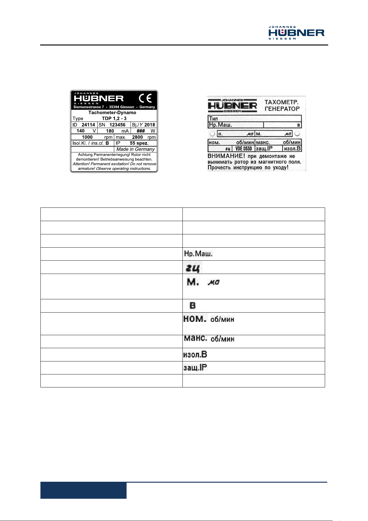
3 Technical Data
ENGLISH
RUSSIAN
Manufacturer, address
Manufacturer
CE mark
_
S/N = Serial number
= Serial number
Y = year of construction
= year of construction
[mA] = Maximum permissible current
= Maximum current [mA]
[W] = Rated power
= Rated voltage [V]
[rpm] = Rated speed
= nominal speed [rpm]
max. rpm = Maximum speed [rpm]
= Maximum speed [rpm]
Isol. Kl./ Cl = Isolation class
= Isolation class
IP = Degree of protection
= Degree of protection
ID = Artikel
Please note: The details on the nameplate apply exclusively to a purely resistive load. The details
differ for inductive or capacitive loads (please consult the manufacturer).
3.1 Type plate
The type plate is located on the side of the housing and contains the following information:
Electrical design to VDE 0530

D.C. tachometer generator TDP 1,2
10
TDP1,2-MANUALen_R5(2018-12-19)ID74713 .doc
TDP S 1,2 G N – 3 spez (Example)
+ FSE 102 overspeed switch
+ B16/3
+ FG 4 (FG 40)
Special version ( version different from normal)
Voltage version (Description 0,6 up to 14)
see tables preferred voltages/special voltages
page 13 – 18
Magnetic shunt ring
Galvanically and mechanically separate
Frame size
S-Short (short version)
L-Long (long version)
TDP = Tachometer - Dynamo – Permanent magnet
Optional
3.2 Type key

D.C. tachometer generator TDP 1,2
11
TDP1,2-MANUALen_R5(2018-12-19)ID74713 .doc
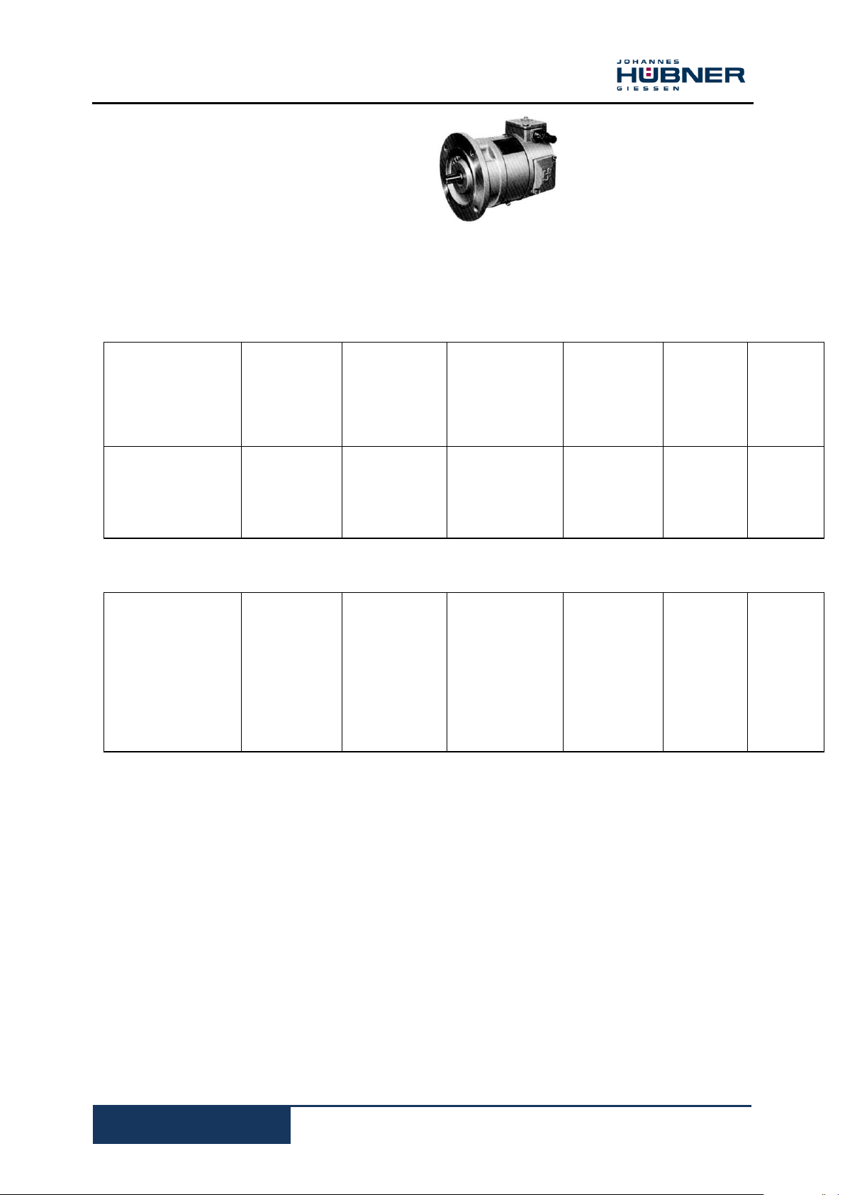
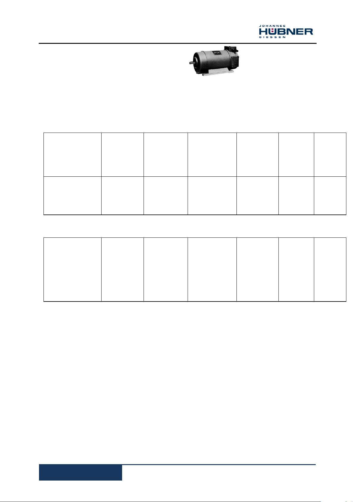
Single tacho-generator
Type: TDP 1,2
TDPS 1,2
TDPL 1,2
- One magnet system
- One armature winding
- Voltage gradient TDP 1,2
20V up to 280V at 1000 rpm
TDPS 1,2
20V up to 200V at 1000 rpm
TDPL 1,2
45V up to 400V at 1000 rpm
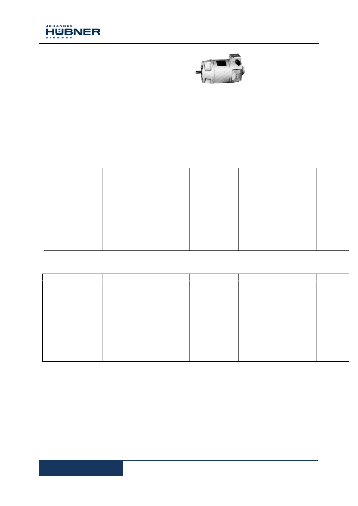
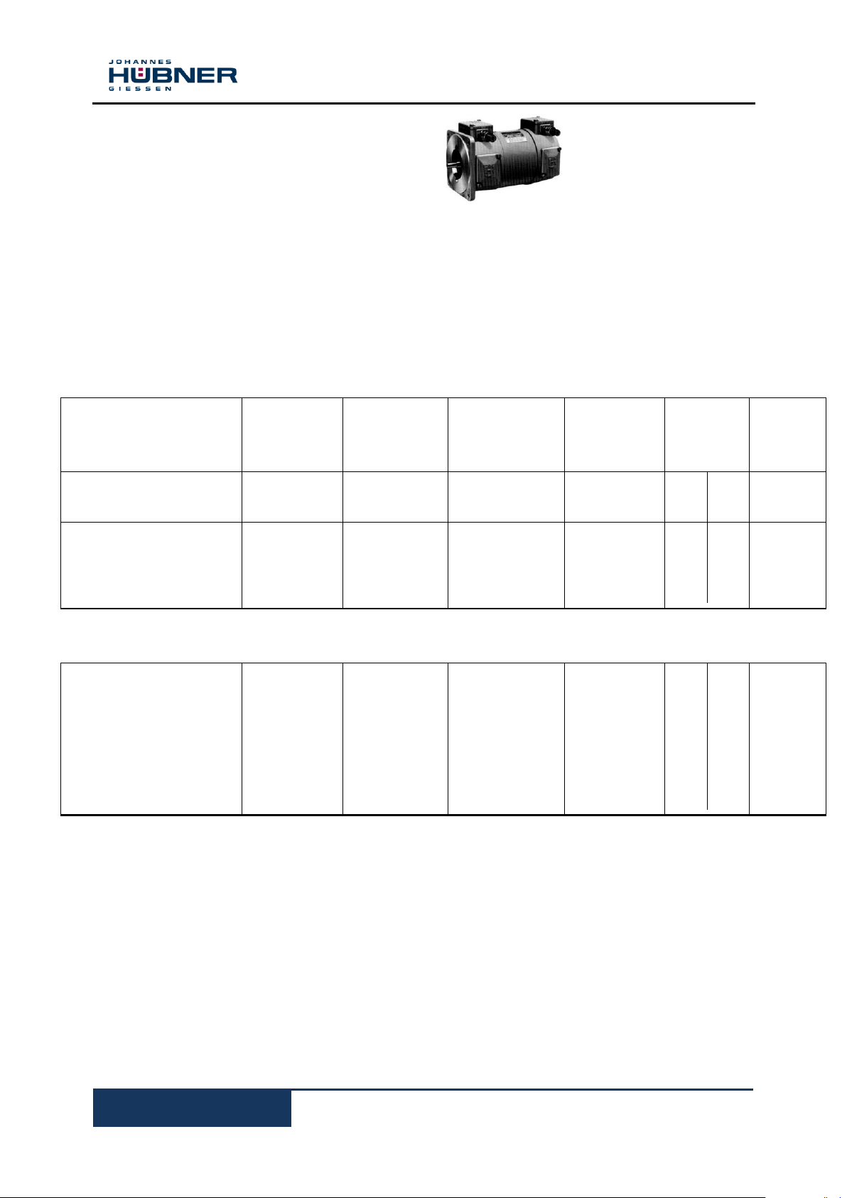
Double tacho-generator
Type: TDP 1,2 + TDP 1,2
TDPS 1,2 + TDPS 1,2
- One magnet system
- Two galvanically separated armature winding
- Voltage gradient 20V up to 200V at 1000 rpm
Double tacho-generator
Type: TDPS 1,2 + TDPS 1,2 G
- Two magnet systems
- Two galvanically and mechanically separated
Armature windings
- Voltage gradient 20V up to 200V at 1000 rpm
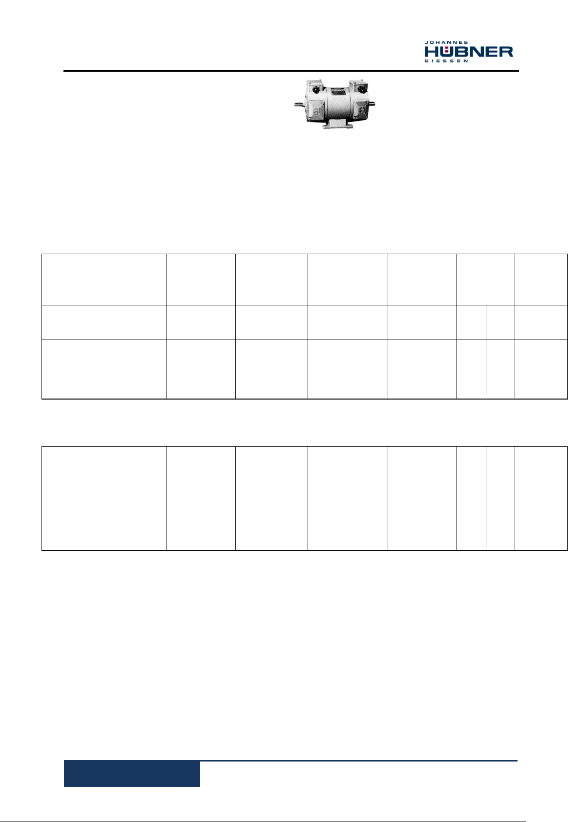
Double tacho-generator
Type: TDP 1,2 + TDF 1,2
- One permanent magnet
- One separate magnet
- Two galvanically and mechanically
separated
Armature windings
Magnetic shunt
Type: TDP 1,2 N
TDPS 1,2 + TDPS 1,2 N
TDPS 1,2 + TDPS 1,2 GN
For the voltage adjustment of one system an additional magnet shunt ring can be installed in these tacho –
generators.
The voltage adjustment amounts to ± 15% referring to the nominal voltage and can be set during operation.
3.3 Type explanation
D.C. tachometer generator TDP 1,2
12
TDP1,2-MANUALen_R5(2018-12-19)ID74713 .doc
Indication
Value
Unit
Weight
See chapter 13 dimension drawings /mechanical data
kg
Dimensions
See chapter 13 dimension drawings /mechanical data
mm
Open circuit voltage (DC)
See type plate on machine
V DC
Rated voltage with load (DC)
See type plate on machine
V DC
Maximum rated current
See type plate on machine
A DC
Machine-Temperature range
- 40 to + 100
°C
Maximum speed
See type plate on machine
rpm
3.4 Dimensions, Power consumption, Environment, Speed
3.5 Elektrical and mechanical data
D.C. tachometer generator TDP 1,2
13
TDP1,2-MANUALen_R5(2018-12-19)ID74713 .doc
Type
Rated voltage at
1000 rpm
[15W]
Max.
speed
Max. permissible
current
Optimum
load
resistance
Armature
resistance
at 20 0 C
approx.
No-load-
voltage
at
1000
rpm
[V]
[rpm]
[mA]
[kΩ]
[Ω]
[V]
TDPS 1,2- 1
200
2000
75
175
320
226
TDPS 1,2- 3
140
2800
107
83
178
158
TDPS 1,2- 5
100
4000
150
43
82
113
TDPS 1,2- 8
65
6000
230
17
30
73
TDPS 1,2- 12
30
6000
500
3,7
6,3
34
TDPS 1,2- 2
175
2300
86
135
221
198
TDPS 1,2- 4
115
3500
130
56
94
129
TDPS 1,2- 6
90
4400
167
36
58
101
TDPS 1,2- 7
75
5300
200
23
39
84
TDPS 1,2- 9
55
6000
273
14
23
62
TDPS 1,2- 10
45
6000
333
9
15
51
TDPS 1,2- 11
35
6000
428
5,5
8,8
40
TDPS 1,2- 13
25
6000
600
2,6
4,1
29
TDPS 1,2- 14
20
6000
750
2,1
2,5
23
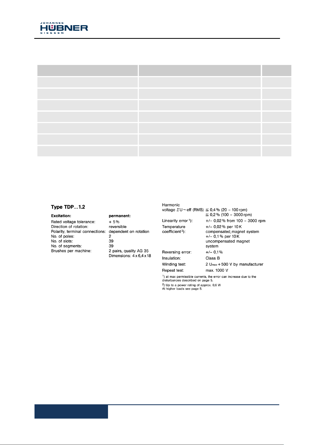
Type TDPS 1,2
Rated power at 1000 rpm 15 W
Moment of inertia approx. 7 kgcm2
Breakaway torque approx. 12 Ncm
Weight approx. 8 kg
Preferred voltages
Special voltages
D.C. tachometer generator TDP 1,2
14
TDP1,2-MANUALen_R5(2018-12-19)ID74713 .doc
Type
Rated voltage at
1000 rpm
[15W]
Max.
speed
Max. permissible
current
Optimum
load
resistance
Armature
resistance
at 20 0 C
approx.
No-load-
voltage
at
1000
rpm
[V]
[rpm]
[mA]
[kΩ]
[Ω]
[V]
TDP 1,2- 1
200
2000
125
96
255
220
TDP 1,2- 3
140
2800
180
42
114
154
TDP 1,2- 5
100
4000
250
24
52
110
TDP 1,2- 8
65
6000
385
9,5
21
72
TDP 1,2- 12
30
6000
830
1,8
5,1
33
TDPS 1,2- 0,8
280
1400
90
160
401
308
TDPS 1,2- 0,9
230
1700
110
110
285
253
TDPS 1,2- 2
175
2300
140
66
182
192
TDPS 1,2- 4
115
3500
220
28
75,5
126
TDPS 1,2- 6
90
4400
280
17
41
100
TDPS 1,2- 7
75
5300
333
11
31
82
TDPS 1,2- 9
55
6000
450
6,5
18,2
61
TDPS 1,2- 10
45
6000
550
4,2
12
50
TDPS 1,2- 11
35
6000
720
2,6
6,9
39
TDPS 1,2- 13
TDPS 1,2- 14
25
20
6000
6000
1000
1250
1,5
0,9
3,25
2,2
28
22
Type TDP 1,2
TDP 1,2 N
Rated power at 1000 rpm 25 W
Moment of inertia approx 8 kgcm2
Breakaway torque approx. 12 Ncm
Weight approx. 10 kg
Preferred voltages
Special voltages
D.C. tachometer generator TDP 1,2
15
TDP1,2-MANUALen_R5(2018-12-19)ID74713 .doc
Type TDPL 1,2
Type
Rated voltage at
1000 rpm
[15W]
Max.
speed
Max. permissible
current
Optimum
load
resistance
Armature
resistance
at 20 0 C
approx.
No-load-
voltage
at
1000
rpm
[V]
[rpm]
[mA]
[kΩ]
[Ω]
[V]
TDPL 1,2- 0,6
400
1000
125
105
274
428
TDPL 1,2- 0,8
280
1400
180
61
151
299
TDPL 1,2- 1
200
2000
250
26,5
69
214
TDPL 1,2- 3
140
2800
355
15
38
150
TDPL 1,2- 5
100
4000
500
6,5
17
107
TDPL 1,2- 0,7
350
1140
145
99
240
374
TDPL 1,2- 0,9
230
1700
215
41
100
248
TDPL 1,2- 2
175
2300
285
24
52,4
187
TDPL 1,2- 4
115
3500
435
10,5
25
123
TDPL 1,2- 6
90
4400
555
6
15,3
96
TDPL 1,2- 7
75
5300
665
4,2
10
80
TDPL 1,2- 8
65
6000
770
3,7
7,1
70
TDPL 1,2- 9
55
6000
910
2,5
6,1
59
TDPL 1,2- 10
45
6000
1110
1,5
4,0
48
Rated power at 1000 rpm 50 W
Moment of inertia approx 14 kgcm2
Breakaway torque approx. 12 Ncm
Weight approx. 15 kg
Preferred voltages
Special voltages
D.C. tachometer generator TDP 1,2
16
TDP1,2-MANUALen_R5(2018-12-19)ID74713 .doc
Type
Rated voltage at
1000 rpm
[2x12W]
Max.
speed
Max. permissible
current
Optimum
load
resistance
Armature
resistance
at 20 0 C
approx.
No-load-
voltage
at
1000
rpm
[V]
[rpm]
[mA]
[kΩ]
[Ω]
[V]
[V]
DE
NDE
TDPS 1,2 + TDPS 1,2-1
200
2000
60
175
350
320
220
TDPS 1,2 + TDPS 1,2-3
140
2800
86
83
167
153
154
TDPS 1,2 + TDPS 1,2-5
100
4000
120
43
86
73
110
TDPS 1,2 + TDPS 1,2-8
65
6000
185
17
34
29
72
TDPS 1,2 + TDPS 1,2-12
30
6000
400
3,7
7,4
6,7
33
TDPS 1,2 + TDPS 1,2-2
175
2300
68
135
270
246
192
TDPS 1,2 + TDPS 1,2-4
115
3500
104
56
112
102
126
TDPS 1,2 + TDPS 1,2-6
90
4400
133
36
72
65
100
TDPS 1,2 + TDPS 1,2-7
75
5300
160
23
47
42
82
TDPS 1,2 + TDPS 1,2-9
55
6000
218
14
28
25
61
TDPS 1,2 + TDPS 1,2-10
45
6000
267
9
18
16
50
TDPS 1,2 + TDPS 1,2-11
35
6000
343
5,5
11
10
39
TDPS 1,2 + TDPS 1,2-13
25
6000
480
2,6
5,2
4,7
28
TDPS 1,2 + TDPS 1,2-14
20
6000
600
2,1
4,2
3,8
22
Type TDPS 1,2 + TDPS 1,2
TDPS 1,2 + TDPS 1,2N
Rated power at 1000 rpm 2 x 12 W
Moment of inertia approx 8 kgcm2
Breakaway torque approx. 15 Ncm
Weight approx. 11 kg
Preferred voltages
Special voltages
The electrical data refer to one armature winding, two different voltage versions are available for each
machine.
D.C. tachometer generator TDP 1,2
17
TDP1,2-MANUALen_R5(2018-12-19)ID74713 .doc
Type
Rated voltage at
1000 rpm
[2x25W]
Max.
speed
Max. permissible
current
Optimum
load
resistance
Armature
resistance
at 20 0 C
approx.
No-load-
voltage
at
1000
rpm
DE
NDE
[V]
[rpm]
[mA]
[kΩ]
[Ω]
[Ω]
[V]
TDP 1,2 + TDP 1,2-1
200
2000
125
67,5
169
154
220
TDP 1,2 + TDP 1,2-3
140
2800
180
33
82
77
154
TDP 1,2 + TDP 1,2-5
100
4000
250
18
38
35
110
TDP 1,2 + TDP 1,2-8
65
6000
385
8
15,5
14,3
72
TDP 1,2 + TDP 1,2-12
30
6000
830
2,3
3,7
3,4
33
TDP 1,2 + TDP 1,2-2
175
2300
140
55
133
122
192
TDP 1,2 + TDP 1,2-4
115
3500
220
23
55
51
126
TDP 1,2 + TDP 1,2-6
90
4400
280
13,5
30
27,6
100
TDP 1,2 + TDP 1,2-7
75
5300
333
11,5
22,5
20,7
82
TDP 1,2 + TDP 1,2-9
55
6000
450
5,5
13,3
12,2
61
TDP 1,2 + TDP 1,2-10
45
6000
550
3,7
8,7
8,0
50
TDP 1,2 + TDP 1,2-11
35
6000
720
2,7
5,0
4,6
39
TDP 1,2 + TDP 1,2-13
25
6000
1000
1,7
2,7
2,2
28
TDP 1,2 + TDP 1,2-14
20
6000
1250
1,0
1,6
1,5
22
Type TDP 1,2 + TDP 1,2
Rated power at 1000 rpm 2 x 25 W Moment of inertia approx 15 kgcm2
Breakaway torque approx. 15 Ncm
Weight approx. 16 kg
Preferred voltages
Shaft mounted constructions (overhung mountings) in B10 … construction speeds limited to max.
2500 rpm
Special voltages
The electrical data refer to one armature winding, two different voltage versions are available for each machine.

D.C. tachometer generator TDP 1,2
18
TDP1,2-MANUALen_R5(2018-12-19)ID74713 .doc
Type
Rated voltage at
1000 rpm
[2x25W]
Max.
speed
Max. permissible
current
Optimum
load
resistance
Armature
resistance
at 20 0 C
approx.
No-load-
voltage
at
1000
rpm
DE
NDE
[V]
[1/min]
[mA]
[kΩ]
[Ω]
[Ω]
[V]
TDPS 1,2 + TDPS 1,2 G-1
200
2000
75
175
320
320
226
TDPS 1,2 + TDPS 1,2 G-3
140
2800
107
83
178
178
158
TDPS 1,2 + TDPS 1,2 G-5
100
4000
150
43
82
82
113
TDPS 1,2 + TDPS 1,2 G-8
65
6000
230
17
30
30
73
TDPS 1,2 + TDPS 1,2 G-12
30
6000
500
3,7
6,3
6,3
34
TDPS 1,2 + TDPS 1,2 G-2
175
2300
86
135
221
221
198
TDPS 1,2 + TDPS 1,2 G-4
115
3500
130
56
94
94
129
TDPS 1,2 + TDPS 1,2 G-6
90
4400
167
36
58
58
101
TDPS 1,2 + TDPS 1,2 G-7
75
5300
200
23
39
39
84
TDPS 1,2 + TDPS 1,2 G-9
55
6000
273
14
23
23
62
TDPS 1,2 + TDPS 1,2 G-10
45
6000
333
9
15
15
51
TDPS 1,2 + TDPS 1,2 G-11
35
6000
428
5,5
8,8
8,8
40
TDPS 1,2 + TDPS 1,2 G-13
25
6000
600
2,6
4,1
4,1
29
TDPS 1,2 + TDPS 1,2 G-14
20
6000
750
2,1
2,5
2,5
23
Type TDPS 1,2 + TDPS 1,2 G
TDPS 1,2 + TDPS 1,2 GN
Rated power at 1000 rpm 2 x 15 W Moment of inertia approx 15 kgcm2
Breakaway torque approx. 15 Ncm
Weight approx. 16 kg
Preferred voltages
Shaft mounted constructions (overhung mountings) in B10 … construction speeds limited to max.
2500 rpm
Special voltages
The electrical data refer to one armature winding, two different voltage versions are available for each machine.

D.C. tachometer generator TDP 1,2
19
TDP1,2-MANUALen_R5(2018-12-19)ID74713 .doc
3.6 General technical data, electric implementation
Magnet system design
The magnet system of these machines consists of two permanent block magnets, developed especially
for these machines and manufactured in AINi Co alloy.
The direction of magnetization is determined by the material's optimum direction of magnetization. In
order to guarantee operation free of ageing problems, the permanent magnets are aged artificially until
they reach optimum remanent energy density.
CAUTION!
Short circuits should be avoided because of their bad effect on the commutator; any burn
marks can give rise to additional harmonics.
Magnetization, external effects
The machines are magnetised when mounted via an external power source.
The magnetising field strength required to saturate the permanent magnets is about 4000A / cm
CAUTION!
After magnetization, the machine's magnetic circuit must not be interrupted, otherwise a
voltage drop of approx. 25 % occurs. It is vital to follow precisely the dismantling
instructions of the machine (please ask for special leaflet, see page 32).
Any effect on the tacho voltage due to magnetic or electrical field stray is largely prevented by
strongly formed machine yoke.
Insulation
The standard insulation complies with Insulation Class B (VDE 0530). Special insulation types can
be provided to enable the tacho to operate in the following conditions:
Insulation Class F (ambient temperature to max. 100 °C). See temperature coefficient.
Humid and tropical condition
Limited resistance to acid and alkaline fumes Winding test: max. 1000 V on repeat test.

D.C. tachometer generator TDP 1,2
20
TDP1,2-MANUALen_R5(2018-12-19)ID74713 .doc
Voltage
The listed voltages are detailed in the technical tables for the different, available machine types.
Intermediate values and special voltages are possible (optional)
When values are lower than the listed voltages (<10 V) the listed power rating must be reduced to 1/50
(brush voltage drop). Use version G if voltage values below the listed values (<10 V) are required
when utilizing double tacho-generators.
Nominal voltage tolerance
The nominal voltage tolerance indicates the deviation of the set voltage from the nominal value. It is
obtained from the energy contents of the permanent magnets being used, which are also subject to
tolerance. This results in different values from machine to machine when setting the operating point.
The maximum tolerance is +5%. A tighter voltage tolerance ± 1% is possible.
Power available
The maximum available power given in the selection tables is always referred to the rated speed of
1000 rpm. Should this power be fully utilised, the user should note that the linearity error worsens
(approx. 0,5% at 1000 rpm). The maximum permissible current, which is given in the selection tables,
should not be exceeded at maximum permissible speed.
Connections, polarity
Connection: Single tacho to a 2-pole terminal board. Double tacho to two 2-pole terminal boards.
Terminal board bolt size M 4.
When rotation is clockwise, the machine (seen from DE) has terminal A 1 positive and terminal
A 2 negative polarity.
See page 29
Construction with 15 pin industry plug (optional).
Terminal box
1 terminal box for single tachos
2 terminal boxes for double tachos (Note: Double tacho with tapered shaft only, 1 terminal box).
Pg 11, cable Ø 7,5-9 mm

D.C. tachometer generator TDP 1,2
21
TDP1,2-MANUALen_R5(2018-12-19)ID74713 .doc
7
Maximum speed
The maximum speeds listed in the tables are restricted on the one hand by the max. permissible
segment voltage and on the other hand by the permissible peripheral speed. In special cases
appropriate design measures make it possible to exceed the maximum speeds listed in the tables. It
is possible that the maximum speed will have to be reduced when utilizing machines with built-in shaft
seals.
Reversing error
To obtain the same voltage values in both directions the carbon brushes are positioned in the
electrical "neutral zone". When reversing the tacho-generator voltage changes because the contact
surfaces of the brushes are practically never in the neutral zone. There are two causes for the change
in voltage, which results on the one hand from the distortion of the exciter field due to the reaction of
the armature when under load, and depends on the tilt of the brushes in the holder on the other. The
reversing error in the most unfavourable of circumstances is ± 0.5%.
Brushes, brushholder
The quality AG 35 (with 65% silver content) of the silver-graphite brushes guarantees long and
maintenance-free operation.
The combination of silver-graphite brushes with the commutator, which is also silver-plated, causes
a patina to form which ensures that the voltage drop due to contact resistance is very low and
remains nearly constant over a long period of operation. Useful brush life is highly dependent on
the ambient air conditions and the peripheral speed. Under normal operating conditions it is
approx. 20000 operating-hours.
In aggressive ambient air conditions the bakelitebound brush, Quality BG 62, has proved itself. It
does, however, have a higher contact resistance. If the commutator surface is smooth, the patina
should not be removed during regular machine maintenance.
The brush holders used are standard solid double type with a specific brush pressure of 3 N/cm2.
If the machine is likely to be exposed to heavy vibration and shock loads, it is recommended that the
brush holder has a relatively high specific brush pressure of approx. 6 N/cm2. Machines of protection
types IP 56/IP 55 spec. generally have a higher brush pressure.

D.C. tachometer generator TDP 1,2
22
TDP1,2-MANUALen_R5(2018-12-19)ID74713 .doc
Rotational frequency
Pole frequency
Keyway frequency
Segment frequency
Temperature coefficient Temperature compensation
The temperature coefficient of the permanent magnets used is dependent on the material used and
is approx. +/- 0,10% per 10 degrees K of temperature change. This value applies to a temperature
range of approx. - 40°C to + 100 °C and is reversible.
The variation can be reduced by as much as 5 times by providing temperature compensation in the
form of soft magnetic material. If temperature compensation is required, this should be specified on
ordering (extra cost).
≙ Temperature error (due to change in resistance) [%]
≙ Temperature change [K]
≙ Armature resistance [Ω]
≙ Armature current [A]
≙ Load voltage [V]
The voltage drop measured between full load and no-load can also be utilized instead of the product
obtained by multiplying RA and IA. The temperature error stated in the tables was measured in the
laboratory whilst subject to a continual increase in temperature of approx. 20 K per hour. The error
can be higher if the rate of temperature increase is faster or the machine is subjected to radiated heat
on just one side. An optional version with temperature compensation is available. It is possible to
compensate the temperature course of the permanent magnet to a tolerance of ±0.2‰ per 10 K in
the temperature range 0 to 100 °C.
Harmonics
An essential characteristic of a good tacho voltage is one which, over a large speed range has a low
percentage harmonic content. In general, the RMS value of the total harmonic mix is measured by
thermionic voltmeter and referred to the D.C. voltage value. The harmonic voltage is approx. 0,2 %
at speeds between
100 and 3000 rpm. Machine harmonics result from the mechanical and electrical design and the
electrical utilisation, as well as production tolerances of symmetry.
Frequency analysis defines the following typical basic frequencies with their harmonics.

D.C. tachometer generator TDP 1,2
23
TDP1,2-MANUALen_R5(2018-12-19)ID74713 .doc
Attachment harmonics, arising from coupling or fitting faults, influence the generator voltage because
Ub = Reference voltage
nb = Reference speed
Gb = Reference gradient
Um = Measured tacho voltage
nT = Tacho speed
Frel = relative linearity error
[‰]
they are superimposed on the machine harmonics. In general, two fitting faults occur: phase-angle
errors and parallel misalignment. The frequency of the resulting harmonics generated corresponds to
that occurring at twice a given speed (phase angle) or once that value (parallel misalignment). By
precise fitting of attachments it is possible to keep such harmonics relatively small.
Linearity
The usability of a tacho-generator in the broadest possible range of control applications is limited
by the linearity of the output voltage relative to speed.
Definition of the linearity error:
Every analysis of an error is relative, and for that reason depends on the method of measurement used
to determine the error. The quotient obtained from the deviation of the measured and the arithmetical
voltage calculated with the aid of the defined reference gradients at 1500 rpm and the reference voltage
at 1500 rpm is known as the linearity error.

D.C. tachometer generator TDP 1,2
24
TDP1,2-MANUALen_R5(2018-12-19)ID74713 .doc
Description of the method of measurement used to determine linearity:
The tacho-generator to be tested is coupled to a prime mover fitted with a flywheel and operated
through a speed range of 100 to 3000 rpm. An incremental encoder (1000 pulses/rotation) is used to
measure the speed digitally to one decimal place. The tacho voltage is also measured digitally,
however, this is measured to three decimal places. A printer connected to both measuring devices
prints the voltage and speed. The measurements are taken at intervals of 100 rpm. At least 20
measured values are printed per measurement. The reference voltage at a speed of 1500 rpm is
selected as a reference point for all voltages and associated speeds.
The quotient obtained from the voltage at 1500 rpm and the speed of 1500 rpm is known as the
reference gradient. The voltages and speeds from 10 measured values respectively are
arithmetically averaged when evaluating the gradients and the gradient formed from these averaged
values.
Disturbance variables relative to linearity
Load current and armature reaction
If it is assumed that the speed-voltage curve at no load is a straight line at a particular angle, then
when load is applied (without taking account of armature reaction) the result is a straight line at a
less steep angle. The difference depends on
However, as the magnetic flux is distorted and weakened by the load current a further change
occurs to the voltage characteristic curve. The voltage drop resulting from the armature reaction
approximately follows the load current more or less according to a quadratic function and, therefore,
results in a slightly curved speed voltage curve when under load. Suitable design measures,
however, make it is possible to keep the field distortion caused by the armature reaction extremely
low. The max. permissible load current is provided for the respective machine type; however, the
linearity errors listed in the selection tables refer to the current resulting from termination with the
optimum load resistance. (Frel = 0.2‰, at max. permissible current 5‰.)

D.C. tachometer generator TDP 1,2
25
TDP1,2-MANUALen_R5(2018-12-19)ID74713 .doc
Brush contact voltage
Silver-graphite brushes with very low contact voltage are mainly used for D.C. tacho-generators.
The total voltage drop at the sliding contact commutator is affected by peripheral speed, current
density under the brushes, brush pressure, and the condition of the patina on the brush contact face.
The load resistance should not be made too high.
The load resistance should be 200 to 1000 times the machine internal resistance in order to
guarantee the specified linearity.
Summary: it can be said that the load resistance must not exceed or fall below a set limit value if the
specified linearity error is to be maintained. If the terminal resistance is too low, then armature
reaction has an adverse effect on linearity; if it is too high the effects of the commutator can increase
the linearity error.
Special purpose machines
DC tacho-generator with separate exciter Type TDF 1,2
For special closed-loop control tasks it is imperative that the output voltage of a tacho-generator does
not change in proportion to the speed, but that it adheres to a certain mathematic function. For this
purpose it is possible to use separately excited DC tacho-generators, which operate in the nonsaturated range with the lowest possible remanent voltage. The output voltage is speed proportionate
when a constant excitation current is applied. However, if the excitation current is altered according to
the speed the output voltage depends on two variables, which makes it possible, for example, to
achieve a quadratic dependence between voltage and speed.
Technical data
Output power at 1000 rpm 10 W
Armature voltage user selectable between 20 and 200 V
Excitation voltage user selectable between 10 and 200 V

D.C. tachometer generator TDP 1,2
26
TDP1,2-MANUALen_R5(2018-12-19)ID74713 .doc
Speed-voltage
curve of the
permanent
magnet DC
tacho
generator
Speed-voltage curve of
the separately excited
DC tacho-generator in
conjunction with speedproportional excitation
by the permanent
tachometer-generator
mounted on the same
shaft.
DC double-tacho-generator with permanent and separate excitation
Types TDP 1,2 + TDF 1,2
This is single-shaft machine comprising a permanent magnet tacho-generator and a separately
excited tacho-generator. The speed-proportional voltage of the permanent magnet machine is used to
excite the separately excited generator. As a consequence, the output voltage of the separately
excited tacho-generator changes with the speed according to a quadratic function. The voltage
characteristics are depicted in the diagrams below.
Technical data
Output power at 1000 rpm 10 W
Armature voltage user selectable between 20 and 200 V

D.C. tachometer generator TDP 1,2
27
TDP1,2-MANUALen_R5(2018-12-19)ID74713 .doc
4 Mechanical design
Construction types
To DIN EN 60 034-7; IEC 34-7 (replaces DIN 42950). Modified versions have an additional letter
added. (B 5 s, B 5 k, B 10 s, B 5 g ...).
The different construction types are shown in the dimension drawings. All flange construction types
can additionally be fitted with a foot (for example: B35...).
The use of strengthened spheroidal graphite iron is recommended when attachments are long and
heavy (specify when ordering).
All tachos can have a B 14 flange and 2nd shaft extension at the NDE (NDE end shield) (optional).
Construction reference example:
B 3/B 14 or B 14/B 14. The machines can also be mounted vertically, without modification. Tachos in
protection type IP 55 spec. may need a change of the air vent position.
Other construction types are available on request.
Degrees of protection:
Standard versions of the units meet the requirements of IP 55 to DINNDE 0530 part 5; IEC 34-5;
EN 60 034 part 5 for rotating electrical machines (replaces DIN 40050 sheet 2).
IP 55 - Fully enclosed. Protection against harmful dust deposits and against water spray from all
directions.
Special protection types - IP 56, IP 55 spec. are used where unfavourable environmental or ambient
conditions exist, such as: jet-water, temporary flooding,
oil mist, high humidity, heavy accumulations of dust (suitable for installation in open air), heavy
vibration and shock loads. Additionally, the machines are suitable for use in an extended temperature
range from - 40°C to + 100°C. The brush holders produce a relatively high brush pressure of
approximately 6 N/cm2.
The ball bearings, which have packing washers, also have a special grease for use in a temperature
range of - 60 °C to + 120 °C.
The shaft exit at the DE is sealed with an axial shaft sealing ring.
A condensation water drain hole is located at the NDE on the underside. The commutator can also be
cleaned and polished through this opening.
IP 56 - Totally enclosed, protected against damaging dust deposits and temporary flooding
IP 55 spec. - The special feature of this protection type is that the tacho - otherwise as IP 56 - has a
vent in addition.
An exchange of air between tacho interior and the environment can take place; the formation of
condensation is largely prevented or can leak out through the wire grid (wire gauze filter
approx. 0.2 x 0.2 mm). Please note that this vent on the underside of the tacho
should be located at the lowest point.

D.C. tachometer generator TDP 1,2
28
TDP1,2-MANUALen_R5(2018-12-19)ID74713 .doc
Note must also be taken of the fitting position. See below for V-construction type vertical mounting
positions.
Vent plug and cover screw are interchangeable, depending on fitting position.
With flange construction type V1, V3, V18 and V19 on request.
2nd shaft extension exit complies with IP 55; higher degrees of protection are obtained only after
fitting the appropriate attachment or shaft cover.
Bearings
The sealed or covered deep-groove ball bearings 1) to DIN 625 are greased for life. They are greased
with lithium-based grease having a dropping point of 180°C, suitable for a temperature range of 60°C to + 120°C.
Fixed Bearing DE (drive end)
Floating Bearing NDE (non-drive end)
Shaft extensions
The tacho normally has 1 free shaft extension,Ø14 k6 x 30 with closed feather keyway to
DIN 6885 P 1. The feather key is also supplied.
In construction types B 10- and B 3-K 20 and ... K 32 a tapered shaft extension (taper 1 : 20) is
supplied having a fine thread. Self-locking hexagon nut which can be used several times is supplied
with the unit.
A cover screw at the NDE guarantees access to the tacho shaft (manual speed measurement).
Special shafts, of smaller diameter and different lengths can be supplied.
The 2nd shaft extension is normally Ø 14 K6 x 30 mm.
Shaft sealing
At DE all tachos can be fitted with a sealing ring 2).
1
) An axial shaft seal is normally fitted when protection is IP 56/IP 55 spec.
We recommend not to exceed speed ranges of approx. 4000 rpm.
2
) For arrangement details, see page 42

D.C. tachometer generator TDP 1,2
29
TDP1,2-MANUALen_R5(2018-12-19)ID74713 .doc
5 Design and function
Electrical connection:
Clockwise rotation: A1 terminal positive
A2 terminal negative
Winding test (repeat) max. 500 V
Suitable connection cable to maintain degree of protection
Fit cover plate and terminal box lid,
machine is ready for operations!
A1 (+) A2 (-)
5.1 Block diagram
Fig. 2: Block diagram clockwise rotation
5.2 Short description
The DC-Tacho-Generator TDP 1,2consists of a permanent magnet stator for excitation and a rotor from
which DC voltage is drawn via carbon brushes. The rotating rotor generates a DC voltage at a given
linear relationship in proportion to its speed.
5.3 Connections
The terminal box is fitted with cable glands. Suitable cables (Pg 11, cable Ø 7.5-9) are necessary to
maintain the degree of protection.

D.C. tachometer generator TDP 1,2
30
TDP1,2-MANUALen_R5(2018-12-19)ID74713 .doc
6 Transport, packaging and storage
6.1 Safety instructions for transport
CAUTION!
Improper transport can cause property damage!
Comply with the symbols and warnings on the packaging.
Handle with care
Protect from moisture
Protect from heat over 40°C and direct sunlight
Protect from moisture
Keep packed goods dry and protected against moisture.
Protect from heat
Protect packaged goods from heat over 40°C and direct sunlight.
6.2 Incoming goods inspection
Check delivery immediately upon receipt for completeness and possible transport damage.
Inform the forwarder directly on receipt of the goods about existing transport damages (prepare
pictures for evidence).
6.3 Packaging (disposal)
The packaging is not taken back and must be disposed of in accordance with the respective statutory
regulations and local guidelines.
6.4 Storage of packages (devices)
If stored for longer periods (> 6 months) we recommend sealing the devices in foil, possibly with a
desiccant.

D.C. tachometer generator TDP 1,2
31
TDP1,2-MANUALen_R5(2018-12-19)ID74713 .doc
7 Installation, commissioning and dismantling
7.1 Uses
DC-Tacho-Generators from the series TDP 1,2 are used to convert rotary motion (rpm) to DC voltage in
proportion to the rotating speed. These encoders are suitable for deployment with larger industrial
drives such as those used in steel and rolling mills, in coal mining operations, in process technology, in
railway systems, in power plants, in marine engineering and so on.
7.2 Place of installation
Installation height < 1000 m above msl. Consult the manufacturer if the installation height is >
1000 m (possible derating)
Permissible ambient temperature - 40 °C to + 100 °C.
Avoid too dry ambient conditions (ensure patina build-up on carbon brush/commutator).
Observe details on nameplate (ratings, protection class and so forth) when operating the DC
tacho-generator.
Do not attach or lean temperature sensitive components onto or against the machine; do not
position such components in the immediate vicinity of the machine.
Ensure sufficient space is available for maintenance work (please refer to 8.2 Inspection and
maintenance schedule)
We recommend installing a canopy for model designs and shaft ends facing downwards; fit a
cover on the plant side if the shaft end faces upwards.
The owner must ensure that no system resonance or vibration arise from interaction between
the machine and plant that could impair the functioning of the machine or result in damage to
the machine or the entire plant or accelerate the ageing process (of the bearings, for
example).
It is the owner's responsibility to undertake suitable measures at the place of installation that
ensure the devices and plant in their totality fulfil the relevant standards applicable to
electromagnetic compatibility.

D.C. tachometer generator TDP 1,2
32
TDP1,2-MANUALen_R5(2018-12-19)ID74713 .doc
7.3 Installation work
7.3.1 Installation and commissioning
Please note:
It is the owner's responsibility to ensure that all moving parts are properly safeguarded and ensure that
the machine is safe to operate!
Observe the max. permissible voltage when repeating the winding test (contact the manufacturer).
It is essential to prevent the ingress of oil or grease into the commutator area! Oil mist as well as
touching the carbon brushes with oily fingers will cause the carbon brushes to wear significantly; this
in turn will lead to the commutator becoming greasy and short-circuits between the segments.
1. Use a zero-play coupling. The armature must rotate easily; the carbon brushes must sit properly in
the brush holders.
2. Ensure precisely centred assembly. Angular misalignment and parallel displacement lead to
additional harmonics. Align added device referring to a harmonics oscillogram (<5‰). Fit and align
overhanging devices with due care and attention. Observe maximum permissible radial eccentricity
0.05 mm. Do not allow radial or axial forces to act on the tacho-generator shaft.
3. Secure machine using flange or foot.
Mount the machine securely without distortion and not subject to vibration. Securely fasten the feet or
flange using standard screws and washers in all of the through holes. It is important to ensure the
correct property class, size and length of engagement on the fastening side (in accordance with VDI
2230 Blatt 1) so that the entire system remains securely and reliably mounted under all operating
statuses. The thread engagement, its stability and strength on the fastening side must be guaranteed
at all times.
The screws must be tightened to the appropriate torque for the property class and thread; screws
must not become loose when the machine is in operation or at a standstill. Use a torque wrench.
Regularly check the fastening screws are seated correctly in accordance with the inspection and
maintenance schedule. Use only flexible couplings; align and adjust the tacho-generator exercising
due care and attention.
Fit coupling components or other fastenings with due care and attention. Support the opposite end of
the shaft (blows will damage the bearings).
If the second shaft is not used secure the key permanently to ensure it cannot be thrown out of the
keyway.
4. Connections in the terminal box.
Check the load against the technical data detailed on the nameplate. Please note: Take account of
surge protectors for downstream devices, if these are connected to the output voltage of the tachogenerator. The output voltage of the tacho-generator increases at a given (linear) relationship in
proportion to the speed.
Connect according to circuit diagram (see wiring diagram).
To guarantee a safe electrical connection the cross-section of the conductors must be sized
in accordance with the rated current as detailed on the nameplate.
Ensure any unused cable glands and the terminal box are sealed dust and water-tight
Create a safe earth connection!

D.C. tachometer generator TDP 1,2
33
TDP1,2-MANUALen_R5(2018-12-19)ID74713 .doc
Before closing the terminal box you must ensure that
The connections have been terminated according to the wiring diagram.
All connections in the terminal box have been securely tightened.
All minimum clearance values have been maintained (greater than 8 mm up to 500 V,
greater than 10 mm up to 750 V)
The inside of the terminal box is clean.
Unused cable glands are sealed and the screw plugs including the seals are tightened
securely.
The gasket seal is clean and properly glued in the lid of the terminal box; ensure all
sealing surfaces are in a proper condition to guarantee the degree of protection.
The rating data match the data detailed on the nameplate.
5. Remove any transport locks before commissioning.

D.C. tachometer generator TDP 1,2
34
TDP1,2-MANUALen_R5(2018-12-19)ID74713 .doc
7.4 Dismantling
Observe and adhere to safety information (2)!
Shut down and ensure the machine cannot be restarted.
Turn off and isolate the power supply; turn off and isolate the power supply to any
additional or auxiliary circuits.
Ensure adjacent live components are insulated and safeguarded.
Examine components for damage and broken edges (for example risk of cuts from
broken off foot).
Exercise due care and attention when removing coupling parts and fastenings; support
the opposite end of the shaft (blows will damage the bearings). Coat the shaft with a thin
layer of oil and seal with screw cap. Ensure the terminal box and cable glands are
sealed dust and water-tight; ensure the degree of protection (see nameplate) is achieved
and guaranteed for transport.
Observe and adhere to transport information (6)!
Ensure that the packaging (carton + palette) used to transport the machine is correctly
sized and that the machine is secured by the packaging in such a manner that forces
resulting from the weight of the machine during transport cannot cause any damage to
the machine, to neighbouring parts or injury to personnel! Use transport locks to reduce
the load acting on the bearings.
Follow and observe the following dismantling instructions for armature exchange.
CAUTION!
Dismantling (disassembly / removing the armature) the fully assembled tacho-generator
TDP 1,2 must always be undertaken by the manufacturer only.

D.C. tachometer generator TDP 1,2
35
TDP1,2-MANUALen_R5(2018-12-19)ID74713 .doc

D.C. tachometer generator TDP 1,2
36
TDP1,2-MANUALen_R5(2018-12-19)ID74713 .doc
Disturbance
Possible cause
Troubleshooting
Voltage to low
Wrong speed
Speed measurement control
Winding short
Voltage check Consulting
producer
Maximum permissible current is
exceeded
Reduce current.
Irrreversibler damage the
magnets (aging)
Magnets magnetize new
(consult manufacturer).
Voltage values at different
rotation unequal
Neutral zone adjusted.
Consulting producer
Bias excitation field by armature
reaction.
Consulting producer
Reversion, tilt the brush in the
holder.
Consulting producer
Harmonics
Burn marks on the commutator,
for example by short circuits.
Cause for short circuits and
repair
Coupling or assembly errors
(misalignment and parallel
misalignment).
Correct the mounting mistake
System-related vibrations and
resonance
Possible causes, contact the
manufacturer.
Rotor rotating hard
Armature short circuit, defective
storage
Decouple machine to look
again, a hard place?
Contact the manufacturer.
Grinding noise
Carbon brush holder from fallen.
Brush back into holder, avoid
strong vibrations.
Rotating parts sand.
Grinding cause notice.
If possible! Remove foreign
matter otherwise contact
manufacturers.
8 Disorders
8.1 Diagnosis Chart

D.C. tachometer generator TDP 1,2
37
TDP1,2-MANUALen_R5(2018-12-19)ID74713 .doc
Bearing makes noise or is
jammed
Note:
Exchange of the bearings only
by the manufacturer.
Mounting error / clutch problem
Mounting precision check
Corroded bearings
Replace bearing by
manufacturer
Insufficient lubrication.
contact the manufacturer.
Too little/much bearing play.
Replace bearings
Contact the manufacturer
Grind marks in the bearing
track, scoring.
Replace bearings; contact the
manufacturer.
Bearing jammed or distorted
Check bearing bore
contact the manufacturer.
Seals rub
Replace seal.
Please contact the
manufacturer
Insufficient lubrication
Please contact the
manufacturer
Bearing corroded
Please contact the
manufacturer.
Too little bearing play
Please contact the
manufacturer
Coupling pushes or pulls
Re-align machine
Belt tensioned too tightly
Adjust belt pulley in line with
specifications.
Bearings jammed or distorted
Contact the manufacturer
Heavy vibration
Rotor imbalance, rotor not
round, shaft distorted
Please contact the
manufacturer
Incorrect alignment
Align set of machines; check
coupling.
Imbalance with the coupled
prime mover
Rebalance the coupled prime
mover
Shocks from coupled
prime mover
Check prime mover
Resonance in the foundations
Strengthen foundations
following consultation with the
manufacturer
Changes in the foundation
Following consultation with the
manufacturer determine the
cause, eliminate error and
realign the machine.

D.C. tachometer generator TDP 1,2
38
TDP1,2-MANUALen_R5(2018-12-19)ID74713 .doc
Carbon brushes wearing
excessively
Brush contact resistance too
high – badly formed patina
(brush contact face commutator contact face) as a
result of the air being too dry.
Change condition of circulating
air
(remedy lack of moisture; avoid
dust in ambient air).
Brush pressure too high
Contact the manufacturer.
Grease on brush contact face
Clean contact face (contact the
manufacturer)
Heavy vibration
* See above.
Surface temperature too high
(>100 °C)
Operated under short-circuit
conditions
Check device; please contact
the manufacturer.
Other faults
Please contact the
manufacturer.

D.C. tachometer generator TDP 1,2
39
TDP1,2-MANUALen_R5(2018-12-19)ID74713 .doc
9 Recommended Inspections
Interval
Inspections
To be carried out by
Regularly
Check fastening screws are seated
correctly
Skilled personnel
After approx. 2000 operating
hours
Check carbon brushes; blow carbon
brush dust out of the machine using dry,
oil-free compressed air; check ease of
movement. When changing carbon
brushes (service life approx. 10 000 –
20 000 operating hours depending on
environmental conditions and speed)
ensure the new brushes are of the same
quality and type. Please note: Double
tacho-generators have 2 commutators
and 2 brush rockers).
Skilled personnel
After approx. 2000 operating
hours
Clean soiled commutators using a clean,
oil-free cloth. Do not remove smooth
patina build-up from contact face.
Remove grooves and polish surface
using fine Emery cloth or skim on lathe
(possibly recut and duburr slots).
Skilled personnel
The here described device is partly maintenance free. Nevertheless, following check is recommended
to guarantee an optimum and undisturbed operation.
9.1 Inspection and maintenance schedule
NOTES!
No other actions are required to be carried out on the device in addition to the following
cyclical inspections described in this inspection schedule. Any attempt to tamper with the
device will result in the warranty being declared null and void!
Caution! Replace the sealing ring on special versions (tacho-generators with speed increasing gear)
after 5000 to 8000 hours of operation. Blow out metal filter of tacho-generators designed with
ventilation vents (IP 55 spec.).
Combined units: Tacho + Pulse encoder, type: TDP 1,2 + FG 4.
The pre - set pulse encoder electronics must not be dismantled by the user. If the pulse encoder is
tampered with in any way, the guarantee is invalidated. Changes of bearing or armature must
therefore be carried out only at our works in Giessen.
Contact the manufacturer when operating any other special version and combinations of devices (e.g.
TDP 1,2 + FSE 102).

D.C. tachometer generator TDP 1,2
40
TDP1,2-MANUALen_R5(2018-12-19)ID74713 .doc
Every 48 months
Check ball bearings for noise, running
smoothly. Service life approx. 20 000
hours (lubricated for life); however,
service life depends on speed,
environmental conditions and load.
Caution! Do not remove the armature
before short-circuiting the magnetic
circuit using an appropriate shortcircuiting ring (otherwise voltage drop of
approx. 25%). Observe dismantling
instructions!
Bearings must be replaced
by the manufacturer or a
certified workshop only.
Regularly (depending on degree
of soiling)
Cleaning:
Blow-clean the machine using dry, oil-
free compressed air. Do not use
cleaning agents that damage the
coating. Do not use inflammable
cleaning agents.
Skilled personnel
Regularly
Check coating.
If the protective coating is sufficiently
damaged, repaint to prevent risk of
corrosion (recommended).
Skilled personnel
If the machine has not been in
use for a long time (more than 6
months).
Check the insulation resistance of the
windings (greater approx. 1-5 megaohm). To measure the insulation
resistance disconnect all outgoing lines
from the generator. Contact the
manufacturer if the resistance reading is
less than 1 mega-ohm.
Skilled personnel

D.C. tachometer generator TDP 1,2
41
TDP1,2-MANUALen_R5(2018-12-19)ID74713 .doc
Electrical connection:
Clockwise rotation: A1 terminal positive
A2 terminal negative
Winding test (repeat) max. 500 V
Suitable connection cable to maintain degree of protection
Fit cover plate and terminal box lid,
machine is ready for operations!
10 Disposal
The manufacturer is not obligated to take back electronics waste. The device consists of hybrid
components, and in part must be disposed of as special waste (electronic scrap) according to countryspecific legislation.
Local municipal authorities or specialized disposal companies provide information on environmentally
responsible disposal.
NOTES!
When ordering replacement parts always specify the serial number of the device!
List of spare parts see on page 42.
11 Annex
11.1 Connection diagram
TDP 1,2 ...
Clamping strip (Terminal box):

D.C. tachometer generator TDP 1,2
42
TDP1,2-MANUALen_R5(2018-12-19)ID74713 .doc
12 Spare parts
Spare parts are available on demand via the service address on page 2.
NOTES!
When ordering spare parts, always state the serial number of the device.

D.C. tachometer generator TDP 1,2
43
TDP1,2-MANUALen_R5(2018-12-19)ID74713 .doc
TDP 1,2
Construction type B5/B3
HM 83 M 53 023
13 Dimension drawings

D.C. tachometer generator TDP 1,2
44
TDP1,2-MANUALen_R5(2018-12-19)ID74713 .doc

D.C. tachometer generator TDP 1,2
45
TDP1,2-MANUALen_R5(2018-12-19)ID74713 .doc

D.C. tachometer generator TDP 1,2
46
TDP1,2-MANUALen_R5(2018-12-19)ID74713 .doc
B35 construction HM 83 M 53023

D.C. tachometer generator TDP 1,2
47
TDP1,2-MANUALen_R5(2018-12-19)ID74713 .doc

D.C. tachometer generator TDP 1,2
48
TDP1,2-MANUALen_R5(2018-12-19)ID74713 .doc
Single- or double tacho with mounted coupling
Type: HKI 97-112-K 20/…
According to dimension drawing HM 80 M 51411

D.C. tachometer generator TDP 1,2
49
TDP1,2-MANUALen_R5(2018-12-19)ID74713 .doc
Single tachos
Single- or double tacho with mounted coupling
Type: HKI 97-112-K 20/…
According to dimension drawing HM 80 M 51411

D.C. tachometer generator TDP 1,2
50
TDP1,2-MANUALen_R5(2018-12-19)ID74713 .doc
B35 construction HM 83 M 53044

D.C. tachometer generator TDP 1,2
51
TDP1,2-MANUALen_R5(2018-12-19)ID74713 .doc

D.C. tachometer generator TDP 1,2
52
TDP1,2-MANUALen_R5(2018-12-19)ID74713 .doc

D.C. tachometer generator TDP 1,2
53
TDP1,2-MANUALen_R5(2018-12-19)ID74713 .doc

D.C. tachometer generator TDP 1,2
54
TDP1,2-MANUALen_R5(2018-12-19)ID74713 .doc
13.1 Screw tightening torques
Screws used to mount the machine (screw material, the material pairings to be fastened and the
length of thread engagement) are to be calculated to VDI 2230 (Page 1). The materials used and the
construction to which the generator is to be fastened must guarantee a permanently secure and
reliable joint. The owner is obliged to inspect and ensure compliance with all specifications.
 Loading...