

Hubner FGH 40, K-2048G-90G-NG/20P, KK-2048G-90NG/20P, KK-2048G-90G-NG-S/20P, K-1024S-N/20P Operating And Assembly Instructions Manual

English
Operating and Assembly Instructions
Incremental Hollow-Shaft Encoder FGH 40
Read the Operating and Assembly Instructions prior to
assembly, starting installation and handling!
Keep for future reference!
Translation of the original Operating and Assembly Instructions FGH40_MANUAL-en_R10(2018-10-31)ID74492.doc
ID 74492

Incremental Hollow Shaft Encoder FGH 40
2
FGH40_MANUAL-en_R10(2018-10-31)ID74492.doc
Trademark
Brand names and product names are trademarks or registered trademarks of their respective owner.
Protected trademarks bearing a ™ or ® symbol are not always depicted as such in the manual.
However, the statutory rights of the respective owners remain unaffected.
Manufacturer / publisher
Johannes Hubner
Fabrik elektrischer Maschinen GmbH
Siemensstraße 7
35394 Giessen
Germany
Phone: +49 641 7969 0
Fax: +49 641 73645
Internet: www.huebner-giessen.com
E-Mail: info@huebner-giessen.com
The manual has been drawn up with the utmost care and attention. Nevertheless, we cannot exclude
the possibility of errors in form and content. It is strictly forbidden to reproduce this publication or parts
of this publication in any form or by any means without the prior written permission of Johannes
Hubner Fabrik elektrischer Maschinen GmbH.
Subject to errors and changes due to technical improvements.
Copyright © Johannes Hubner
Fabrik elektrischer Maschinen GmbH
All rights reserved.

Inkrementaler Hohlwellen Drehgeber FGH 40
FGH40_MANUAL-en_R10(2018-10-31)ID74492.doc
3
Directory
1 General ............................................................................................................................ 5
1.1 Information about the Operating and Assembly Instructions ....................................... 5
1.2 Scope of delivery ....................................................................................................... 5
1.3 Explanation of symbols .............................................................................................. 5
1.4 Disclaimer .................................................................................................................. 6
1.5 Copyright ................................................................................................................... 6
1.6 Guarantee terms ........................................................................................................ 6
1.7 Customer service ....................................................................................................... 6
2 Safety ............................................................................................................................... 6
2.1 Responsibility of the owner ........................................................................................ 6
2.2 Intended use .............................................................................................................. 6
2.3 Non- intended use ...................................................................................................... 7
2.4 Personnel ................................................................................................................... 7
2.5 Personal protective equipment ................................................................................... 7
2.6 Special dangers ......................................................................................................... 7
2.6.1 Electrical current .................................................................................................... 7
2.6.2 Rotating shaft / Hot surfaces ................................................................................. 7
2.6.3 Safeguarding against restart .................................................................................. 7
3 Technical Data ................................................................................................................ 8
3.1 Type plates ................................................................................................................ 8
3.2 Electrical and mechanical data ................................................................................... 9
3.2.1 For pulse rates (square wave pulses) .................................................................... 9
3.2.2 Output signals Sine / Cosine ................................................................................10
3.3 Type code .................................................................................................................14
3.3.1 For pulse rates (square wave pulses) ...................................................................14
3.3.2 For output signals Sine / Cosine ...........................................................................15
4 Transport, packaging and storage ...............................................................................16
4.1 Safety instructions for transport .................................................................................16
4.2 Incoming goods inspection ........................................................................................16
4.3 Packaging / disposal .................................................................................................16
4.4 Storage of packages (devices) ..................................................................................16
5 Installation and commissioning ....................................................................................17
5.1 Safety instructions .....................................................................................................17
5.2 Technical information ................................................................................................17
5.3 Required tools ................................................................................................ ...........17
5.4 Mounting preparations ..............................................................................................18
5.5 Mounting hollow-shaft type FGH 40 ..........................................................................18
5.6 Dismantling ...............................................................................................................20
5.6.1 Safety instruction ..................................................................................................20

Incremental Hollow Shaft Encoder FGH 40
4
FGH40_MANUAL-en_R10(2018-10-31)ID74492.doc
5.6.2 Dismantling hollow- shaft type FGH 40 .................................................................20
5.7 Electrical connection and start up ..............................................................................21
5.7.1 Preparing cables ..................................................................................................21
5.7.2 Electrical connection .............................................................................................21
6 Faults ..............................................................................................................................23
6.1 Faults table ...............................................................................................................23
7 Inspections .....................................................................................................................24
7.1 Safety instructions .....................................................................................................24
7.2 Maintenance information ...........................................................................................24
7.3 Inspection schedule ..................................................................................................24
8 Disposal ..........................................................................................................................24
8.1 Disposal procedure ...................................................................................................24
9 Spare Parts .....................................................................................................................24
10 Dimension drawings ......................................................................................................25
10.1 Construction type hollow- shaft .................................................................................25
11 Connection diagrams ....................................................................................................32
Inkrementaler Hohlwellen Drehgeber FGH 40
FGH40_MANUAL-en_R10(2018-10-31)ID74492.doc
5
WARNING!
Indicates a possibly dangerous situation that can result in death or serious injury if it is
not avoided.
CAUTION!
Indicates a possibly dangerous situation that can result in minor injury if it is not
avoided.
CAUTION!
Indicates a possibly dangerous situation that can result in material damage if it is not
avoided.
NOTES!
Indicates useful tips and recommendations as well as information for efficient and
trouble-free operation.
NOTES!
Do not use a hammer or similar tool when installing the device due to the risk of damage
occurring to the bearings or coupling!
DANGER!
Life-threatening danger due to electric shock!
Indicates a life-threatening situation due to electric shock. If the safety instructions are
not complied with there is danger of serious injury or death. The work that must be
executed should only be performed by a qualified electrician.
1 General
1.1 Information about the Operating and Assembly Instructions
These Operating and Assembly Instructions provide important instructions for working with the device.
They must be carefully read prior to starting all tasks, and the instructions contained herein must be
followed.
In addition, applicable local regulations for the prevention of industrial accidents and general safety
regulations must be complied with.
1.2 Scope of delivery
Incremental Hollow-Shaft Encoder FGH 40, Operating and Assembly Instructions.
1.3 Explanation of symbols
Warnings are indicated by symbols in these Operating and Assembly Instructions. The warnings are
introduced by signal words that express the scope of the hazard.
The warnings must be strictly heeded; you must act prudently to prevent accidents, personal injury,
and property damage.
Incremental Hollow Shaft Encoder FGH 40
6
FGH40_MANUAL-en_R10(2018-10-31)ID74492.doc
NOTES!
Content information, text, drawings, graphics, and other representations are protected
by copyright and are subject to commercial property rights.
It is strictly forbidden to make copies of any kind or by any means for any purpose other
than in conjunction with using the device without the prior written agreement of the
manufacturer. Any copyright infringements will be prosecuted.
DANGER!
This section provides an overview of all the important safety aspects that ensure
protection of personnel, as well as safe and trouble-free device operation.
If these safety instructions are not complied with significant hazard can occur.
1.4 Disclaimer
All information and instructions in these Operating and Assembly Instructions have been provided
under due consideration of applicable guidelines, as well as our many years of experience.
The manufacturer assumes no liability for damages due to:
Failure to follow the instructions in the Operating and Assembly Instructions
Non-intended use
Deployment of untrained personnel
Opening of the device or conversions of the device
In all other aspects the obligations agreed in the delivery contract as well as the delivery conditions of
the manufacturer apply.
1.5 Copyright
1.6 Guarantee terms
The guarantee terms are provided in the manufacturer’s terms and conditions.
1.7 Customer service
For technical information personnel is available that can be contacted by telephone, fax or email. See
manufacturer’s address on page 2.
2 Safety
2.1 Responsibility of the owner
The device is used in commercial applications. Consequently the owner of the device is subject to the
legal occupational safety obligations and subject to the safety, accident prevention and environmental
protection regulations that are applicable for the device’s area of implementation.
2.2 Intended use
The device has been designed and constructed exclusively for the intended use described here.
Series FGH 40 Incremental Hollow- Shaft Encoders are used for measurement of rotations, for
instance of electrical and mechanical drives and shafts.
Claims of any type due to damage arising from non-intended use are excluded; the owner bears sole
responsibility for non-intended use.
Inkrementaler Hohlwellen Drehgeber FGH 40
FGH40_MANUAL-en_R10(2018-10-31)ID74492.doc
7
DANGER!
Life-threatening danger due to electrical shock!
There is an imminent life-threatening hazard if live parts are touched. Damage to
insulation or to specific components can pose a life-threatening hazard.
Therefore:
Immediately switch off the device and have it repaired if there is damage to the
insulation of the power supply.
De-energize the electrical equipment and ensure that all components are connected for
all tasks on the electrical equipment.
Keep moisture away from live parts. Moisture can cause short circuits.
WARNING!
Danger of injury due to rotating shafts and hot surfaces!
Touching rotating shafts can cause serious injuries.
Therefore:
Do not reach into moving parts/shafts or handle moving parts/shafts during operation.
Close to protect from injury all access openings in flanges with the corresponding plug
screw, and provided you exposed rotating components with protective covers.
Do not open covers during operation. Prior to opening the covers ensure that all parts
have come to a standstill.
The encoder can become hot during prolonged use.
In case of contact risk of burns is existing.
DANGER!
Life-threatening danger if restarted without authorization!
When correcting faults there is danger of the power supply being switched on without
authorization.
This poses a life-threatening hazard for persons in the danger zone.
Therefore:
Prior to starting work, switch off the system and safeguard it from being switched on
again.
2.3 Non- intended use
Do not use the device in potentially explosive areas.
The device must not be subjected to mechanical loads in addition to its own weight and
unavoidable vibration and shock loads that arise during normal operations.
Examples for non-permitted mechanical loads (incomplete list):
- Fastening transport or lifting tackle to the device, for example a crane hook to lift a motor.
- Fastening packaging components to the device, for example ratchet straps, tarpaulins etc.
- Using the device as a step, for example by people to climb onto a motor.
2.4 Personnel
Installation and commissioning as well as disassembly routines must be carried out by skilled technical staff only.
2.5 Personal protective equipment
Wear personal protective equipment such as safety shoes and safety clothing to minimise risks to
health and safety when carrying out work such as installation, disassembly or commissioning. Adhere
to all applicable statutory regulations as well as the rules and standards determined by the owner.
2.6 Special dangers
Residual risks that have been determined based on a risk assessment are cited below.
2.6.1 Electrical current
2.6.2 Rotating shaft / Hot surfaces
2.6.3 Safeguarding against restart
Incremental Hollow Shaft Encoder FGH 40
8
FGH40_MANUAL-en_R10(2018-10-31)ID74492.doc
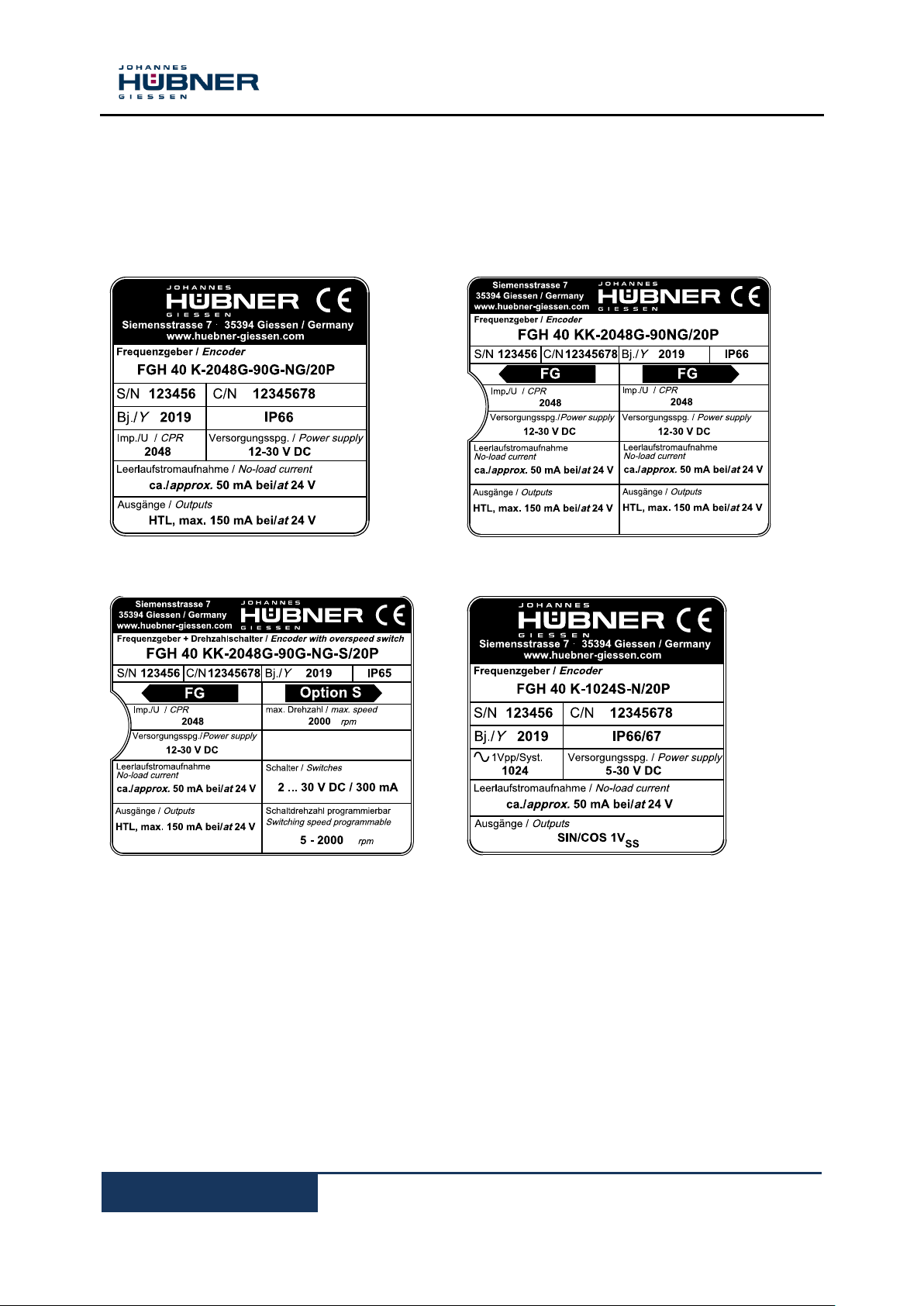
Encoder with 1 terminal box
Encoders with 2 terminal boxes (redundant version)
Encoder with integrated option S
Encoder with 2 sinusoidal signals
3 Technical Data
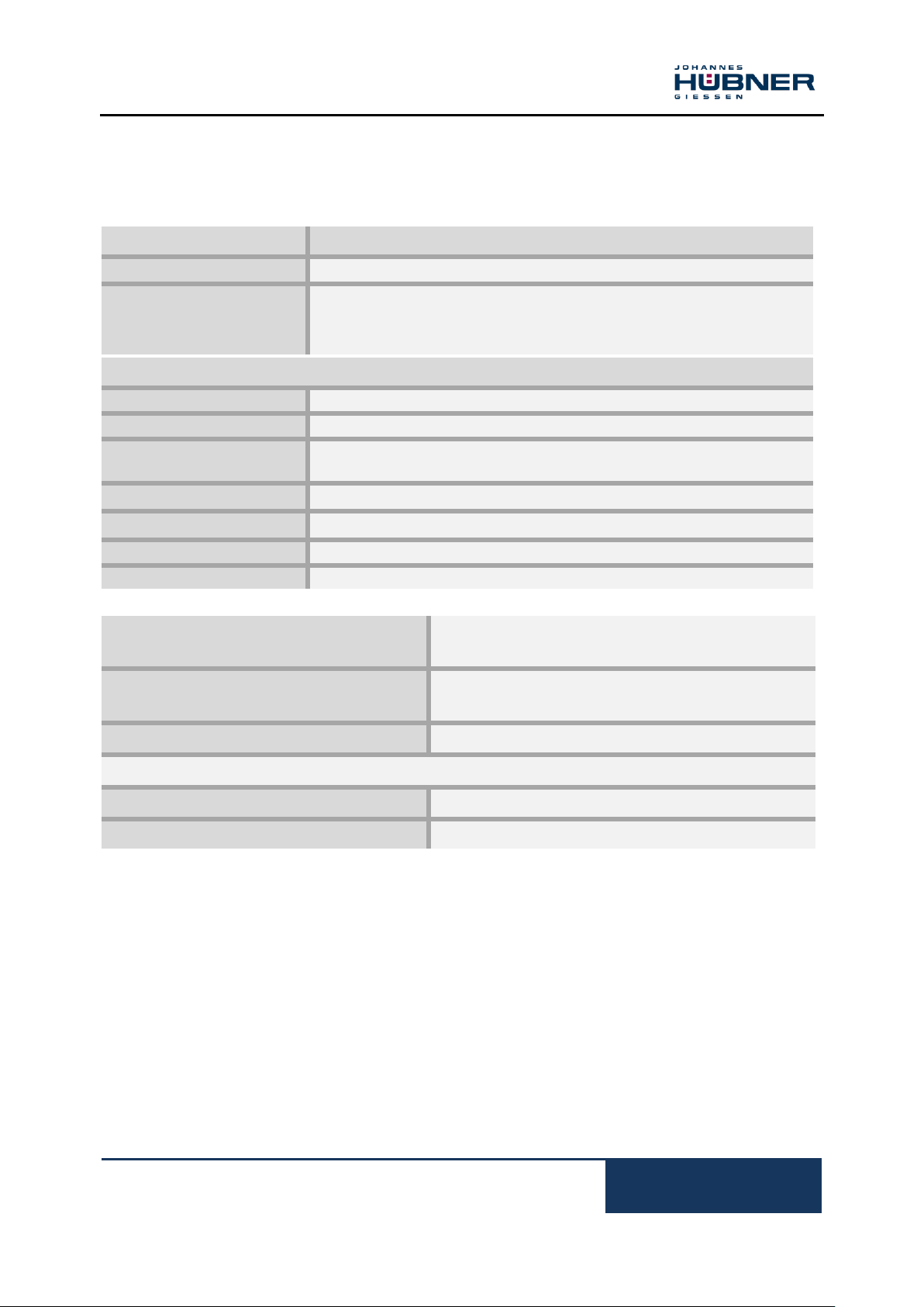
3.1 Type plates
Below are some Example nameplates for different device models shown.
Type plates are located on the outside of the housing and contains the following information:
Manufacturer, Address
Type
CE marking
Serial number (S/N)
Commission number (C/N)
Year of construction
Pulse rate
Protection class
Power supply
No-load current
Outputs
Inkrementaler Hohlwellen Drehgeber FGH 40
FGH40_MANUAL-en_R10(2018-10-31)ID74492.doc
9
Pulse rates
Value
Standard pulse rates
500, 600, 1000, 1024, 1200, 2000, 2048, 2400, 2500
Special pulse rates
4000, 4096, 4800, 5000, 8192, 10000, 12000, 16000, 16384, 20000,
25000, 40000, 50000
(further pulse rates according to customers specification)
Connection data
Supply voltage
12 V … 30 V DC
No load-current
approx. 50 mA at 24 V
Outputs
Current limited, short-circuit proof push-pull line driver with integrated
impedance adaptation for 30 to 140 Ω lines.
Pulse height (HTL)
approx. as supply voltage, output saturation voltage < 0.4 V at IL 30 mA
Output current
max. 150 mA at 24 V (observe derating)
Internal resistance
75 Ω bei 24 V
Slew rate
200 V / µs with CL 100 pF
Duty cycle
1 : 1 ± 3 % for standard pulse rates
1 : 1 ± 5 % for special pulse rates up to 25000 pulses
Square wave displacement 0°, 90°
90° ± 3 % for standard pulse rates
90° ± 5 % or special pulse rates up to 25000 pulses
Max. frequency
200 kHz, Higher max. frequency on request
Special output voltage 5V (TTL)
Pulse height
5V, RS422-compatible (TIA/EIA-Standard)
Supply voltage
12 … 30 V DC (optional: 5 V DC),
3.2 Electrical and mechanical data
3.2.1 For pulse rates (square wave pulses)

Incremental Hollow Shaft Encoder FGH 40
10
FGH40_MANUAL-en_R10(2018-10-31)ID74492.doc
Pulse rates
Value
Standard pulse rates
500, 600, 1000, 1024, 1200, 2000, 2048, 2400, 2500
Connection data
Supply voltage
5 V … 30 V DC
No load-current
Approx. 120 mA at 5 V, approx. 50 mA at 24 V
Max. frequency
200 kHz, higher max. frequency on request
Output signals
2 sinusoidal signals A and B each with inverted signals
Reference pulse with inverted signal
Signal amplitude 1 V pp / RL = 120 Ω
Error signal and inverted signal
Signal amplitude 5V
Resolution
1024 signal periodes
Duty cycle
1 ± 0,1
Phase shift A, B
90° ± 1°
3.2.2 Output signals Sine / Cosine
Inkrementaler Hohlwellen Drehgeber FGH 40
FGH40_MANUAL-en_R10(2018-10-31)ID74492.doc
11
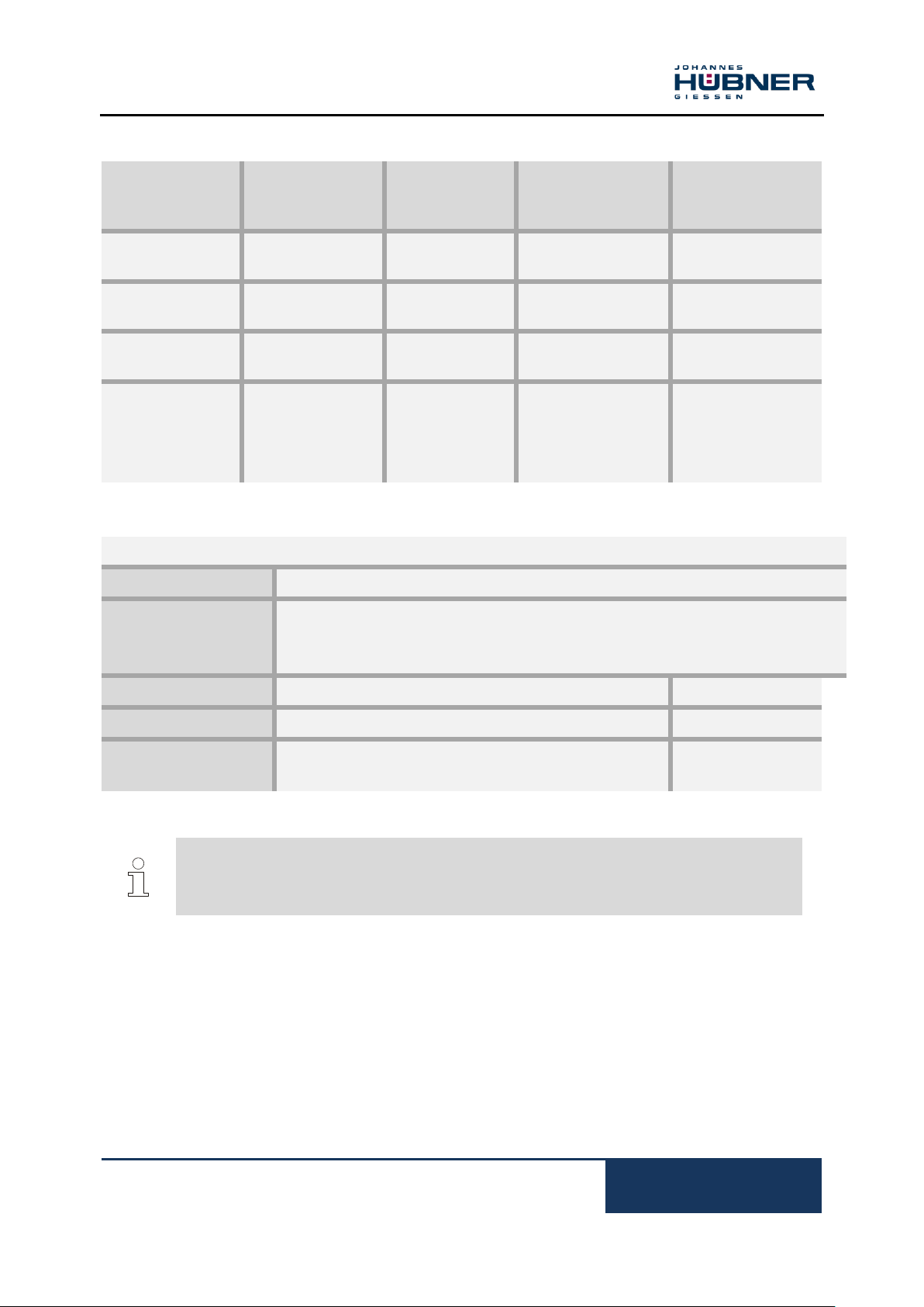
Protection class
acc. to
DIN EN 60529
Sealing
Permissible
speed
Rotor moment of
inertia
Breakaway torque
IP 65
Standard
≤ 4000 rpm
(*) ≤ 3000 rpm
approx. 1175 gcm²
approx. 10 Ncm
IP 66
with labyrinth seal
≤ 4000 rpm
(*) ≤ 3000 rpm
approx. 1325 gcm²
approx. 10 Ncm
IP 66
with axial shaft
seal
≤ 2000 rpm
(*) ≤ 2000 rpm
approx. 1175 gcm²
approx. 25 Ncm
IP 66
with radial shaft
seal (for special
applications, e.g.
wet areas in
rolling mills)
≤ 2000 rpm
(*) ≤ 2000 rpm
approx. 1175 gcm²
approx. 30 Ncm
Encoder temperature range
Standard
0°C… + 70°C
Special temperature
-25°C… + 85°C
-40°C… + 85°C
-5°C… + 100°C
Vibration resistance
DIN EN 60068-2-6 / IEC 68-2-6 (10 … 2000 Hz)
20 g (=200 m/s²)
Shock resistance
DIN EN 60068-2-27 / IEC 68-2-27 (6 ms)
150 g (=1500 m/s²)
Weight
Type FGH 40 K
Type FGH 40 KK
approx. 4,2 kg
approx. 4,5 kg
NOTES!
The hollow shaft device FGH 40 reduces the degree of protection to IP 65, if the cover
plate is not mounted. At maximum speed the permissible ambient temperature will be
reduced to 60°C.
(*) with isolated bearings – hybrid bearings –

Incremental Hollow Shaft Encoder FGH 40
12
FGH40_MANUAL-en_R10(2018-10-31)ID74492.doc
Signal outputs for pulse rates (square wave pulses)
Basic version
Basic channel 0° (A) and pulse channel 90° (B)
Internal system diagnostics with error
output (ERROR)
Each with inverted signals
Option N
Reference pulse (N) mechanically defined; one
square-wave pulse per revolution; with inverted
signal
Option 2F
Twice as many pulses as basic channel by
combining the 0° and 90°channels
Option B
Rapid direction of rotation detection at each edge
of the 0° and 90°channels
Can be combined with Option F
Option B2
Rapid direction of rotation detection at each edge
of the 0° and 90° channels; additional standstill
recognition
Option B3
Rotation-dependent output signals. This option
supports counter cards with separate UP/DOWN
pulse inputs. Basic channel signals are issued at
option output 1 when rotation is clockwise and at
option output 2 when rotation is counterclockwise.
Option S
Electronic overspeed switch with two
independently programmable switching points
See separate Operating and Assembly
Instructions EGS® 40
Fiber optic option
As an alternative to conventional signal
transmissions via copper cables encoder signals
can also be transmitted via fiberoptic cables.
Max. frequency 100 kHz
N
N
The signal sequence 0°, 90° applies for clockwise rotation seen from the drive shaft direction.
To obtain the same signal sequence for counter clockwise rotation the clamp 0°, 90° has to be
connected see connection diagram.

Inkrementaler Hohlwellen Drehgeber FGH 40
FGH40_MANUAL-en_R10(2018-10-31)ID74492.doc
13
Signal outputs for output signals sine / cosine
Basic channel 0° (A) and pulse
channel 90° (B).
Reference pulse (N) mechanically
defined; one square-wave pulse per
revolution; with inverted signal
Each with inverted signal.
Internal system diagnostics with error
output (ERROR).

Incremental Hollow Shaft Encoder FGH 40
14
FGH40_MANUAL-en_R10(2018-10-31)ID74492.doc
FGH
J
40 K 1024
G
90G
NG
2F S /20P
Incremental
hollow-shaft encoder
Isolated bearings
Series
connections, radial design
K: Terminal box
R: Burndy®-plug
C: Connection cable
L: Fiber optic connection
S: 15-pole EMC industrial plug
KK: 2 terminal boxes, i.e. redundant
version or with option S
further combined connections available
Pulses per revolution
Basic signal output
Basic channel 0° (A)
Pulse channel 90° (B)
Each with inverted signals
NG: Option reference pulse with inverted signal
N2: Reference pulse, mechanically fixed with LED
check (red)
for display of reference pulse
2F: Option 2F
B: Option B
B2: Option B2
B3: Option B3
S: Option S
Inner diameter
(by hollow shaft design)
20 P (standard) P: feather key
16 P, 19P, (optional)
16 K, 25 K (optional K: clamping
3.3 Type code
3.3.1 For pulse rates (square wave pulses)

Inkrementaler Hohlwellen Drehgeber FGH 40
FGH40_MANUAL-en_R10(2018-10-31)ID74492.doc
15
FGH
J
40 K 1024
S
N
/20P
Incremental
hollow-shaft encoder
Isolated bearings
Series
connections, radial design
K: Terminal box
R: Burndy®-plug
C: Connection cable
S: 15-pole EMC industrial plug
KK: 2 terminal boxes, i.e. redundant
version
Resolution
1024 signal periodes per revolution
Output signals
2 sinusoidal signals A and B each with inverted signals
NG: Option reference pulse with inverted signal
Inner diameter
(by hollow shaft design)
20 P (standard) P: feather key
16 P, 19P, (optional)
16 K, 25 K (optional K: clamping
3.3.2 For output signals Sine / Cosine

Incremental Hollow Shaft Encoder FGH 40
16
FGH40_MANUAL-en_R10(2018-10-31)ID74492.doc
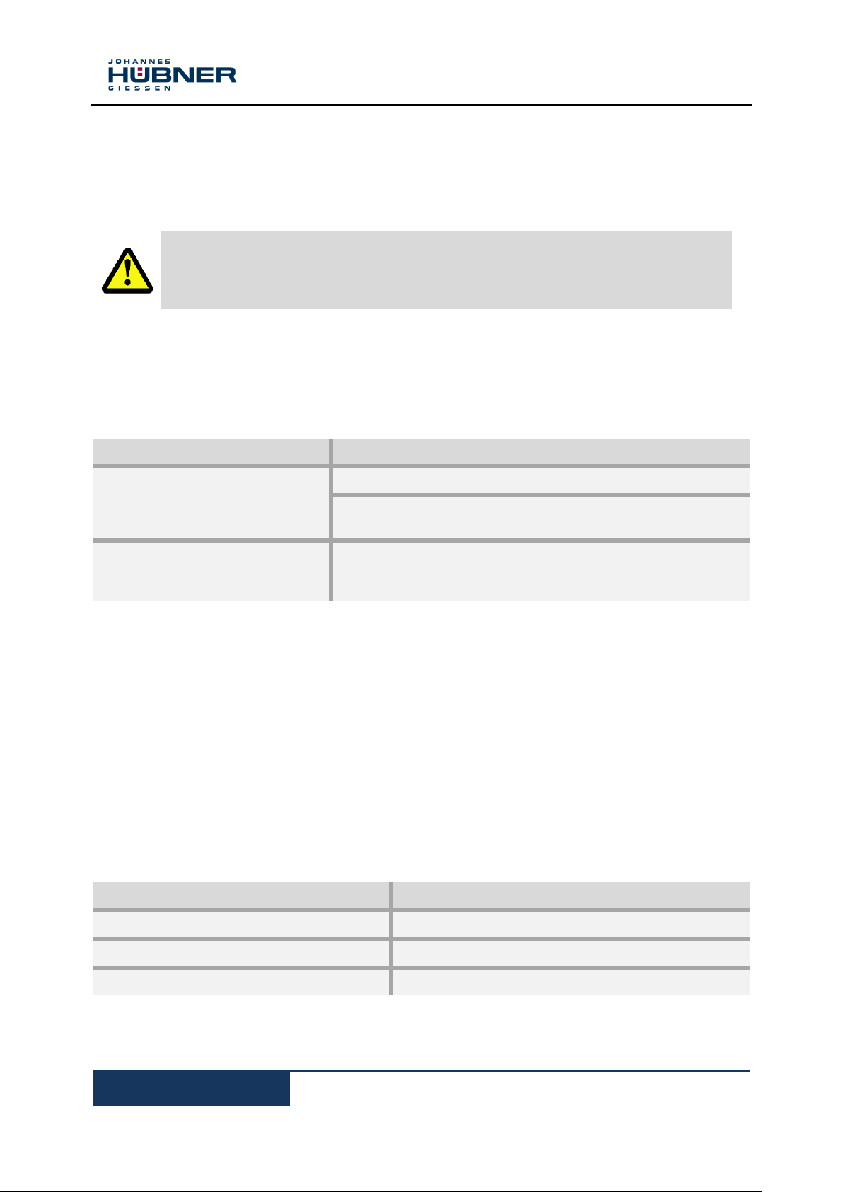
CAUTION!
Material damage caused by improper transport!
Observe the symbols and information on the packaging:
Do not throw - risk of breakage
Keep dry
Do not expose to heat above 40 °C or direct sunlight.
Keep dry
Keep packages dry and free from dust; protect from moisture.
Protect against heat
Protect packages from heat above 40 °C and direct sunlight.
NOTES!
Turn the shaft of the device every 6 month to prevent the bearing grease solidifying!
4 Transport, packaging and storage
4.1 Safety instructions for transport
4.2 Incoming goods inspection
Check delivery immediately upon receipt for completeness and possible transport damage.
Inform the forwarder directly on receipt of the goods about existing transport damages (prepare
pictures for evidence).
4.3 Packaging / disposal
The packaging is not taken back and must be disposed of in accordance with the respective statutory
regulations and local guidelines.
4.4 Storage of packages (devices)
If you intend to store the device for a longer period of time (> 6 months) we recommend you use
protective packaging (with desiccant).

Inkrementaler Hohlwellen Drehgeber FGH 40
FGH40_MANUAL-en_R10(2018-10-31)ID74492.doc
17
NOTES!
Observe the safety instructions contained in Chapter 2 when installing or working on the
device!
NOTES!
Do not use a hammer or similar tool when installing the device due to the risk of damage
occurring to the bearings or coupling!
5 Installation and commissioning
5.1 Safety instructions
Personnel
Installation and commissioning must be carried out by skilled technical staff only.
5.2 Technical information
Ambient temperature
The max. permissible ambient temperature depends on the speed and degree of protection of the
device, the signal frequency, the length of the signal cable and the place of installation (please refer to
Chapter 3.2).
Degree of protection
To fulfil degree of protection requirements the diameter of the connection cable must correspond to
that of the cable gland (please refer to Chapter 10 Dimension drawings)!
Deep groove ball bearings
FGH 40 incremental hollow- shaft encoders are fitted with maintenance-free, greased "for-life" deep
groove bearings. Bearings must be changed by the manufacturer only. Opening the encoder renders
the guarantee null and void.
Screw retention
We recommend using Loctite® 243 thread locker (medium strength) on all fastening screws to prevent
loosening.
5.3 Required tools
Spanners: 10 mm, 14 mm, 22 mm, 24 mm
Allen keys: 5 mm
Flat-blade screwdrivers:
Assembly grease
Loctite® 243 (medium strength thread locker)

Incremental Hollow Shaft Encoder FGH 40
18
FGH40_MANUAL-en_R10(2018-10-31)ID74492.doc
NOTES!
Fastening screws and earth cable are not included in the range of supply.
NOTES!
The maximum radial run-out of the adapter shaft is 0.05 mm.
If necessary, use the ball thrust adjustment screw to align the adapter shaft. Secure ball
thrust screws with Loctite® 243. Remove unused ball thrust screws or secure with
Loctite® 243. Max. tightening torque for M12 approx. 25 Nm, for M16 approx. 35 Nm.
Use parallel keys to DIN 6885.
Please also observe the supplement data sheet Mounting accuracy for hollow shaft
encoders.
You should also observe the Installation instructions supplied with the adapter shaft
when installing!
1 8 2
3
12
7
6
13
10
15
14
5
4
9
11
Figure.1
5.4 Mounting preparations
1. Ensure all accessories are available (please refer to Chapter 10 Dimension drawings).
2. Preparing the place of attachment: Clean the (motor) shaft, centering, bolting surfaces and
fastening threads; check for damage. Repair any damage!
5.5 Mounting hollow-shaft type FGH 40
1. Mount adapter shaft (1) and align using dial gauge.
Inkrementaler Hohlwellen Drehgeber FGH 40
FGH40_MANUAL-en_R10(2018-10-31)ID74492.doc
19
NOTES!
When fitting to the device is possible to align the torque bracket in four different
directions. If possible fit the device in a manner that ensures the cable gland points
downwards! Exchange the position of the cable gland (12) and the blanking plug on the
opposite side, if necessary.
NOTES!
The axial tensioning disc is supplied with several hexagon head socket cap screws of
different lengths. To select the suitable hexagon head socket cap screw please refer to
the dimensioning drawings in Chapter 10.
The hexagon head socket cap screws are coated with a microencapsulated adhesive as
locking agent.
NOTES!
Once fitted the link rod must rotate easily around the link rod heads! Failure to observe
this point may result in damage to the bearings!
NOTES!
The link heads are maintenance free. However, ensure they remain free from soiling
and paint!
2. Lightly grease the adapter shaft.
3. Secure the torque bracket (3) to the hollow-shaft device (13) with 4 tensilock screws (2).
4. Mount the hollow-shaft device to the adapter shaft.
5. Secure the hollow-shaft device with the aid of the axial tensioning disc (6) and a hexagon socket
head cap screw (7).
6. Fit the cover (14) and secure with four countersunk screws (15) to seal the hollow-shaft device.
7. Fastening the torque bracket:
Fastening without base plate:
Secure the link rod head (11) of the link rod (8) to a fixed point (for example on the motor
housing).
Fastening with base plate:
Secure the base plate (9) to a fixed point with two hexagon head screws (10) – (for example on
the motor housing or the foundations).

Incremental Hollow Shaft Encoder FGH 40
20
FGH40_MANUAL-en_R10(2018-10-31)ID74492.doc
WARNING!
Observe the safety instructions contained in Chapter 2 when dismantling the device!
NOTES!
Do not use a hammer or similar tool when installing the device due to the risk of damage
occurring to the bearings or coupling!
NOTES!
Use the withdrawal device D-53663a (available as an accessory) if you are unable to
remove the device manually from the adapter shaft after having removed the axial
tensioning disc)!
Special tool Withdrawal device D-53663a
Using the withdrawal device, which is screwed into the withdrawal thread M25 x 0.75 of
the hollow shaft allows you to remove the overspeed switch from the adapter shaft
without risking damage to the bearings.
5.6 Dismantling
5.6.1 Safety instruction
Personnel
Dismantling must be carried out by skilled technical staff only.
5.6.2 Dismantling hollow- shaft type FGH 40
Disconnect all electrical cable prior to beginning any work.
To dismantling the encoder follow the instructions given in Chapter 5.5 in the reverse order.

Inkrementaler Hohlwellen Drehgeber FGH 40
FGH40_MANUAL-en_R10(2018-10-31)ID74492.doc
21
NOTES!
You must observe applicable EMC guidelines when routing cables!
CAUTION!
Do not allow moisture to enter the terminal box when the cover is open!
NOTES!
The signal cable shielding can be connected directly to the housing via the EMC cable
gland. A coil spring intergrated in the cable gland ensures all-round contact is made with
the bare cable shielding to ensure a good shield connection. This type fo shield
connection should be preferred.
Alternatively, if equipotential boning currents are anticipated it is possible to connect the
cable shielding to a shield terminal in the terminal box. A capacitor between the shield
terminal and the encoder housing prevents the flow of equalizing current.
To achieve an effective shielding the cable shield must also be connected in the
electrical cabinet.
NOTES!
Prior to delivery cable glands and blanking plugs are tightened finger tight only. To
ensure that the terminal box is reliably sealed tighten all cable glands and blanking plugs
before starting up for the first time.
5.7 Electrical connection and start up
5.7.1 Preparing cables
1. Strip cable insulation.
2. Crimp wire-end ferrules.
5.7.2 Electrical connection
1. Open the terminal box cover (16).
2. Remove the cap of the cable gland (12, Fig.1).
3. Feed the cable into the terminal box trough the cable gland.
4. Tighten the cable gland and blanking plugs using a spanner.
5. Use a spanner to tighten the cable gland until the cable is securely clamped and properly sealed.

Incremental Hollow Shaft Encoder FGH 40
22
FGH40_MANUAL-en_R10(2018-10-31)ID74492.doc
NOTES!
Prevent lateral pulling forces acting on the cable and plugs so as not to impair the
degree of protection of the cable gland.
CAUTION!
Do not apply supply voltage to the signal outputs, as this will destroy the device!
NOTES!
To achieve a good shielding effect the cable shield be kept as short as possible.
NOTES!
Before closing the terminal box cover check and if necessary clean both seal surfaces
and the gasket.
CAUTION!
Ensure when closing the terminal box cover that no cable becomes jammed.
6. Connect the supply voltage and signal cable (please refer to the connection diagrams, Chapter 11).
7. Applicable to alternative shield connection only: fit cable lug to cable shield and connect to the
shield terminal (please refer to the connection diagrams, Chapter 11).
8. Close the terminal box cover.
9.Secure earth cable to earth terminal.

Inkrementaler Hohlwellen Drehgeber FGH 40
FGH40_MANUAL-en_R10(2018-10-31)ID74492.doc
23
Faults
Possible cause
Remedy
Moisture in the terminal box
Soiled terminal box gasket or
seal surfaces
Clean terminal box gasket and
seal surfaces
Damaged terminal box gasket
Replace terminal box gasket
Cable gland/blanking plug not
tightened
Tighten cable gland/blanking
plug
Unsuitable cable for cable gland
Use suitable cable and cable
glands
No output signals
Supply voltage not connected
Connect supply voltage
Connection cable reversed
Wire correctly
Output signals subject to
interference
Unsuitable cable
Use data cable with conductors
arranged as twisted pairs and
common shield
Cable shield not connected
Connect cable shield at both
ends
Cable routing not EMC compliant
Observe applicable EMC
guidelines when routing cables
Signal interruptions
Signal end stage overloaded
Check pin assignment; observe
connection diagram
Do not assign unused outputs
Outputs short-circuited
Do not connect outputs with
supply voltage or GND
Contact Hubner-Service (page 2) if none of the remedies listed above provides a solution)!
6 Faults
6.1 Faults table
Incremental Hollow Shaft Encoder FGH 40
24
FGH40_MANUAL-en_R10(2018-10-31)ID74492.doc
WARNING!
Skilled technical staff only are permitted to inspect the device and its installation.
Observe the safety instructions contained in Chapter 2 when inspecting or working on
the device!
Interval
Inspections
Yearly
Ensure the fastening screws are properly tightened
Ensure cable connections and connection terminals are
securely seated
Following approx 16 000 … 20 000
hours of operation / higher levels of
continuous load
Check deep groove ball bearings are running smoothly and
listen for running noises
Spare part
Remark
Cover
Cover of the hollow- shaft bore (non drive end)
Cable gland
M20 x 1,5
Terminal box cover
Incl. Sealing and screws
7 Inspections
7.1 Safety instructions
7.2 Maintenance information
The device is maintenance-free. However, to guarantee optimum fault-free operations we recommend
that you carry out the following inspections.
7.3 Inspection schedule
8 Disposal
8.1 Disposal procedure
The manufacturer is not obliged to take back the device.
The device is classed as electronic equipment and subject to the WEEE Directive; observe local,
country-specific laws when disposing of the device.
For information on environmentally sound disposal please contact your local authority or a specialist
disposal company.
9 Spare Parts
The in the following listed spare parts can be covered when required about the service address on the
page 2.
Inkrementaler Hohlwellen Drehgeber FGH 40
FGH40_MANUAL-en_R10(2018-10-31)ID74492.doc
25
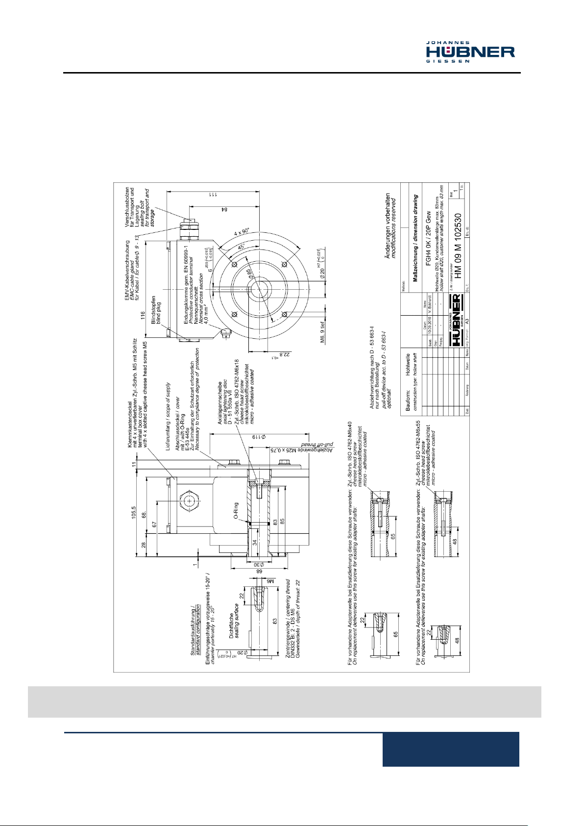
FGH 40 K../20 P Gew
Hollow- Shaft Ø 20, length of
customer shaft max. 83 mm
HM 09 M 102530
10 Dimension drawings
Further dimension drawings on our website or on request.
10.1 Construction type hollow- shaft

Incremental Hollow Shaft Encoder FGH 40
26
FGH40_MANUAL-en_R10(2018-10-31)ID74492.doc
FGH 40 KK../20 P Gew
Hollow- Shaft Ø 20, length of
customer shaft max. 83 mm
HM 09 M 102531

Inkrementaler Hohlwellen Drehgeber FGH 40
FGH40_MANUAL-en_R10(2018-10-31)ID74492.doc
27
FGH 40 KK../20 P Gew
Option S
Redundant version or with
integrated option S
HM 10 M 103037

Incremental Hollow Shaft Encoder FGH 40
28
FGH40_MANUAL-en_R10(2018-10-31)ID74492.doc
FGH 40 K
Assembly with torque bracket
HM 09 M 102203

Inkrementaler Hohlwellen Drehgeber FGH 40
FGH40_MANUAL-en_R10(2018-10-31)ID74492.doc
29
FGH 40 K
Assembly with torque bracket
HM 10 M 101771

Incremental Hollow Shaft Encoder FGH 40
30
FGH40_MANUAL-en_R10(2018-10-31)ID74492.doc
FGH 40 L/LL
additional dimension drawing
electric connection implementation FGH 40 L/LL
fiber optic

Inkrementaler Hohlwellen Drehgeber FGH 40
FGH40_MANUAL-en_R10(2018-10-31)ID74492.doc
31
FGH 40 S/SS
additional dimension drawing
electric connection implementation FG 40 S/SS
15 pole EMC
HM 12 M 105755

Incremental Hollow Shaft Encoder FGH 40
32
FGH40_MANUAL-en_R10(2018-10-31)ID74492.doc
FGH 40
Standard
Terminal box
FGH 40
Standard without reference pulse
Terminal box
11 Connection diagrams
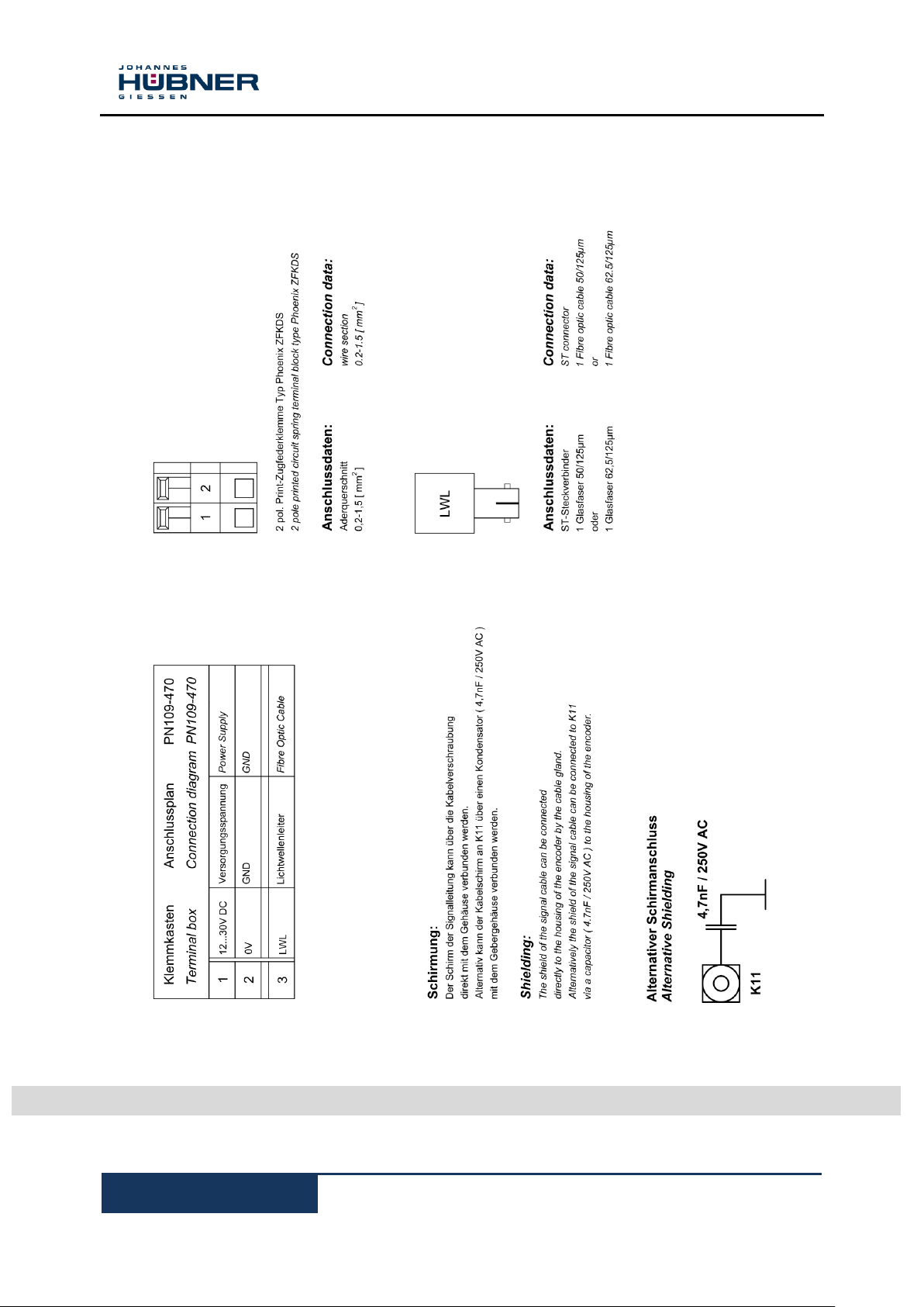
Shielding:
The shield of the signal cable can be
connected
directly to the housing of the encoder by the
cable gland. Alternatively the shield of the
signal cable can be connected to K11 via a
capacitor(10nF / 500V) to the housing of the
encoder.
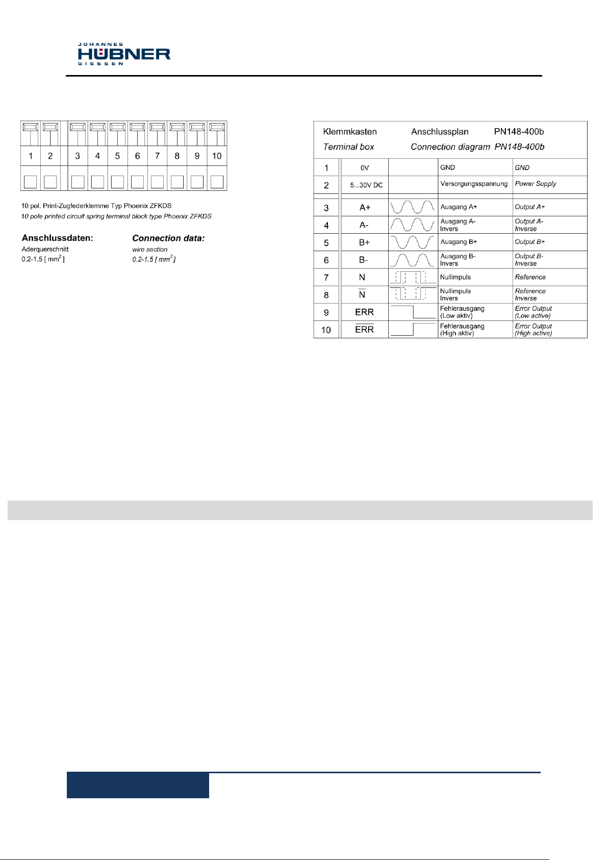
10 pole printed circuit spring terminal block
type Phoenix ZFKDS
Connection data:
wire section
0,2-1,5 [mm²]
Alternative Shielding
Inkrementaler Hohlwellen Drehgeber FGH 40
FGH40_MANUAL-en_R10(2018-10-31)ID74492.doc
33
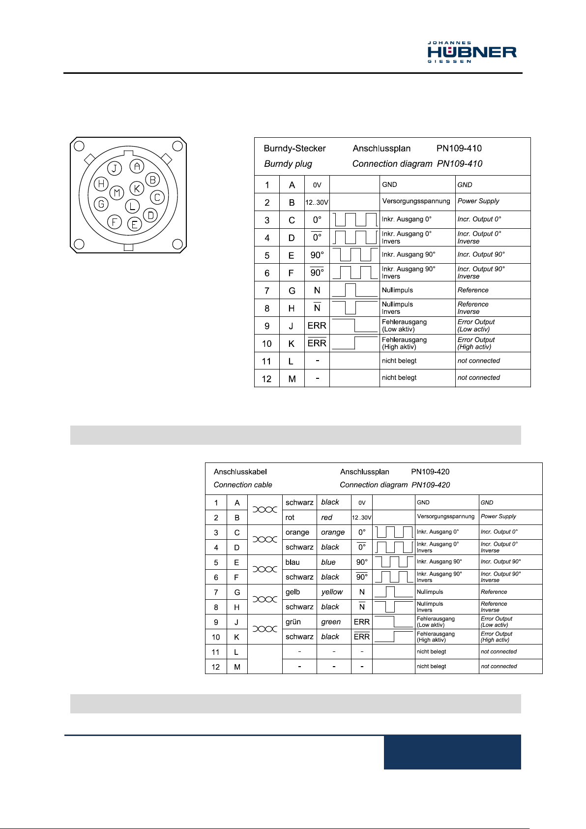
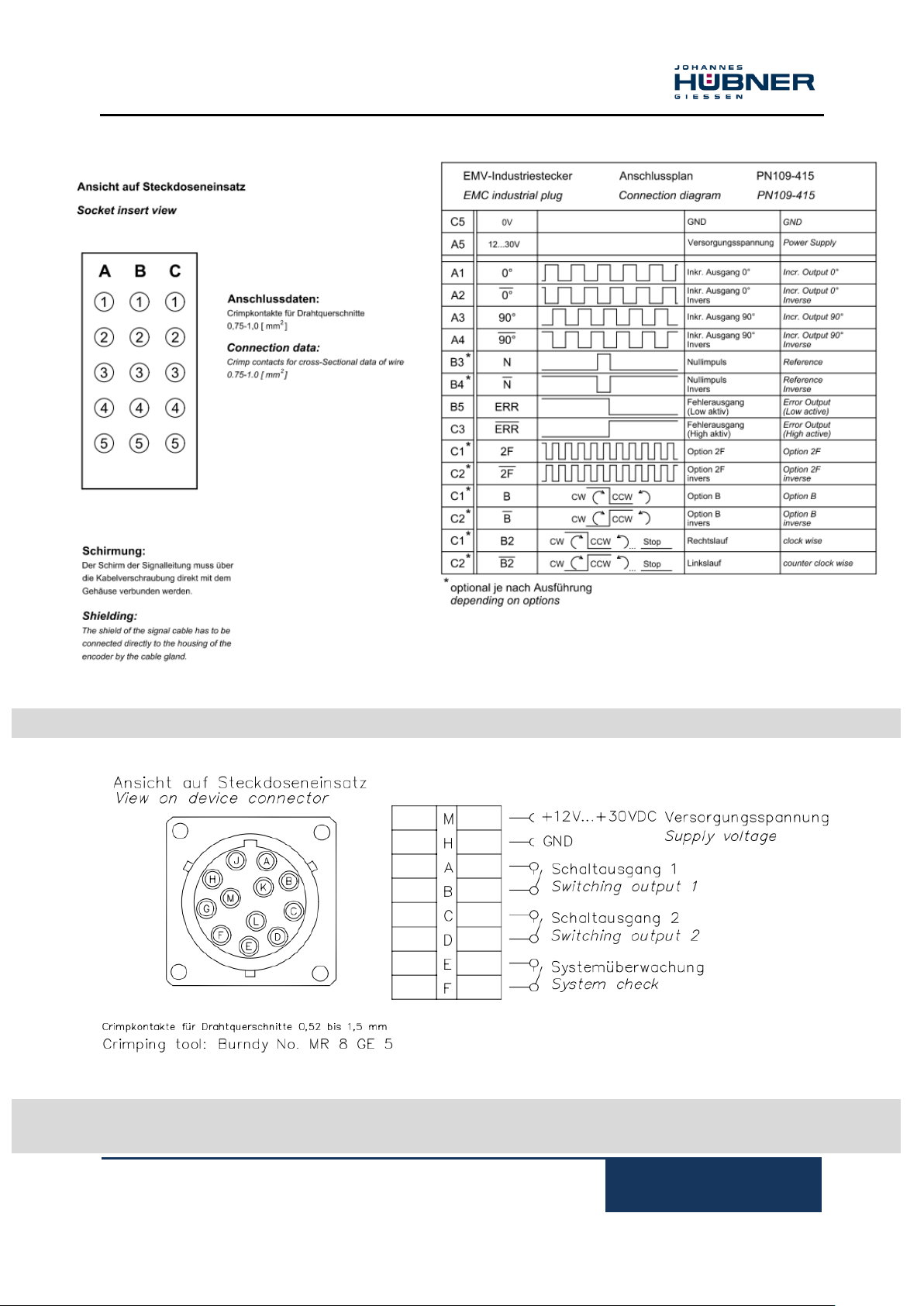
Socket insert view
Shield:
The shield of the signal cable is
directly to be connected with the
socket housing.
Crimping tool: Burndy® No. MR 8 GE 5
FGH 40
Standard
Burndy® plug
Connection cable
6x2x0,56 twin-standard, shielded
Type: HE-2LVCC-CY AWG 20b
acc. to VDE 0881
Cross-section: 0,56 mm²
Temperature: -20 °C to + 105 °C
Outside dia: 10,1 mm
shield is connected to casing
other cables- / temperature ranges
on request
FGH 40
Standard
Connection cable
Crimp contacts for
cross-sectional
data of wire from
0,52 up to 1,5 mm²

Incremental Hollow Shaft Encoder FGH 40
34
FGH40_MANUAL-en_R10(2018-10-31)ID74492.doc
FGH 40
Option F2
Terminal box
FGH 40
Option B
Terminal box
12 pole printed circuit spring terminal block type
Phoenix ZFKDS
Connection data:
Wire section
0,2-1,5 [ mm² ]
Shielding:
The shield of the signal cable can be connected
directly to the housing of the encoder by the
cable gland. Alternatively the shield of the cable
can be connected to K13 via a capacitor (10nF /
500V) to the housing of the encoder.
Alternative Shielding
10 pole printed circuit spring terminal block
type Phoenix ZFKDS
Connection data:
Wire section
0,2-1,5 [ mm² ]
Shielding:
The shield of the signal cable can be connected
directly to the housing of the encoder by the
cable gland. Alternatively the shield of the cable
can be connected to K13 via a capacitor (10nF /
500V) to the housing of the encoder.
Alternative Shielding
Inkrementaler Hohlwellen Drehgeber FGH 40
FGH40_MANUAL-en_R10(2018-10-31)ID74492.doc
35
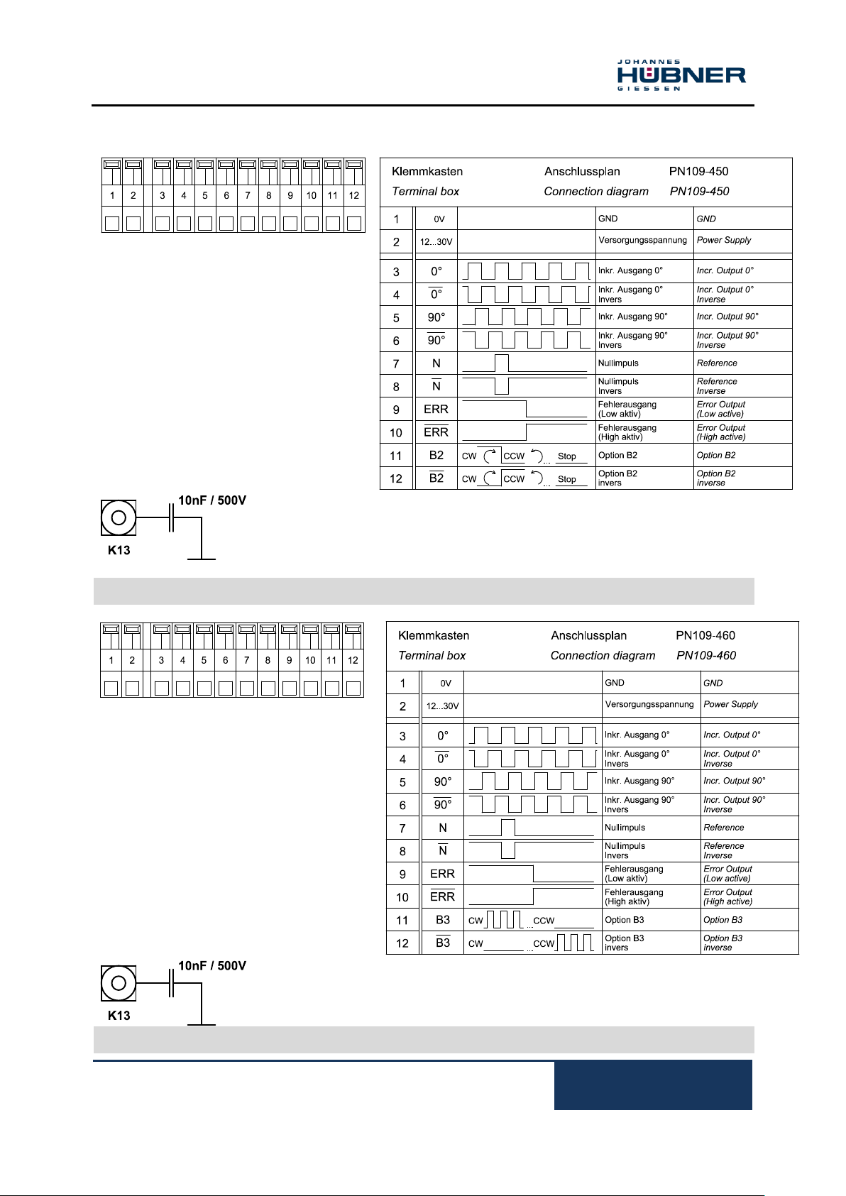
FGH 40
Option B2
Terminal box
FGH 40
Option B3
Terminal box
12 pole printed circuit spring terminal block type
Phoenix ZFKDS
Connection data:
Wire section
0,2-1,5 [ mm² ]
Shielding:
The shield of the signal cable can be connected
directly to the housing of the encoder by the
cable gland. Alternatively the shield of the cable
can be connected to K13 via a capacitor (10nF /
500V) to the housing of the encoder.
Alternative Shielding
10 pole printed circuit spring terminal block type
Phoenix ZFKDS
Connection data:
Wire section
0,2-1,5 [ mm² ]
Shielding:
The shield of the signal cable can be connected
directly to the housing of the encoder by the
cable gland. Alternatively the shield of the cable
can be connected to K13 via a capacitor (10nF /
500V) to the housing of the encoder.
Alternative Shielding
Incremental Hollow Shaft Encoder FGH 40
36
FGH40_MANUAL-en_R10(2018-10-31)ID74492.doc
FGH 40
Connection sheme PN 109-470
Terminal box
Inkrementaler Hohlwellen Drehgeber FGH 40
FGH40_MANUAL-en_R10(2018-10-31)ID74492.doc
37
FGH 40
Connection sheme PN 109-415
EMC industrial plug
FGH 40
Connection sheme 649
Option S
Burndy® plug
Incremental Hollow Shaft Encoder FGH 40
38
FGH40_MANUAL-en_R10(2018-10-31)ID74492.doc
FGH 40
Connection sheme PN 148 400a
Sinue /Cosine Output
 Loading...