


English
Translation of the original Operating and Assembly Instructions FGH14_MANUAL-en_R5(2017-08-14)ID68166.doc
ID 68166
Operating and Assembly Instructions
Incremental hollow shaft encoder FGH 14
Read the Operating and Assembly Instructions prior to
assembly, starting installation and handling!
Keep for future reference!

Incremental hollow shaft encoder FGH 14
2
FGH14_MANUAL-en_R5(2017-08-14)ID68166.doc
Trademark
Brand names and product names are trademarks or registered trademarks of their respective owner.
Protected trademarks bearing a ™ or ® symbol are not always depicted as such in the manual.
However, the statutory rights of the respective owners remain unaffected.
Manufacturer / publisher
Johannes Hubner
Fabrik elektrischer Maschinen GmbH
Siemensstraße 7
35394 Giessen
Germany
Phone: +49 641 7969 0
Fax: +49 641 73645
E-Mail: info@huebner-giessen.com
www.huebner-giessen.com
Headquarters: Giessen
Court of registration: Giessen
The manual has been drawn up with the utmost care and attention. Nevertheless, we cannot exclude
the possibility of errors in form and content. It is strictly forbidden to reproduce this publication or parts
of this publication in any form or by any means without the prior written permission of
Johannes Hubner Fabrik elektrischer Maschinen GmbH.
Subject to errors and changes due to technical improvements.
Copyright © Johannes Hubner Fabrik elektrischer Maschinen GmbH
All rights reserved.

Incremental hollow shaft encoder FGH 14
FGH14_MANUAL-en_R5(2017-08-14)ID68166.doc
3
Directory
1 General ............................................................................................................................ 5
1.1 Information about the Operating and Assembly Instructions ....................................... 5
1.2 Scope of delivery ....................................................................................................... 5
1.3 Explanation of symbols .............................................................................................. 5
1.4 Disclaimer .................................................................................................................. 6
1.5 Copyright ................................................................................................................... 6
1.6 Guarantee terms ........................................................................................................ 6
1.7 Customer service ....................................................................................................... 6
2 Safety ............................................................................................................................... 6
2.1 Responsibility of the owner ........................................................................................ 6
2.2 Intended use .............................................................................................................. 6
2.3 Improper use .............................................................................................................. 7
2.4 Personal protective equipment ................................................................................... 7
2.5 Personnel ................................................................................................................... 7
2.6 Special dangers ......................................................................................................... 8
2.6.1 Electrical current .................................................................................................... 8
2.6.2 Rotating shafts ...................................................................................................... 8
2.6.3 Safeguarding against restart .................................................................................. 8
3 Technical Data ................................................................................................................ 9
3.1 Type plate ................................ .................................................................................. 9
3.2 Electrical and mechanical data ................................................................................... 9
3.3 Type code ................................ .................................................................................12
4 Transport, packaging and storage ...............................................................................13
4.1 Safety instructions for transport .................................................................................13
4.2 Incoming goods inspection ........................................................................................13
4.3 Packaging / disposal .................................................................................................13
4.4 Storage of packages (devices) ................................................................ ..................13
5 Installation and commissioning ....................................................................................14
5.1 Safety instructions .....................................................................................................14
5.2 Mounting of the encoder (mechanical) ......................................................................14
5.2.1 Mounting Instruction for hollow shaft encoder .......................................................14
5.3 Connecting the encoder ............................................................................................16
5.3.1 Connections .........................................................................................................16
5.3.2 Technical information ...........................................................................................17
6 Dismantling ....................................................................................................................17
6.1 Safety instructions .....................................................................................................17
6.2 Dismantling the encoder ...........................................................................................17
7 Faults ..............................................................................................................................18

Incremental hollow shaft encoder FGH 14
4
FGH14_MANUAL-en_R5(2017-08-14)ID68166.doc
7.1 Faults table ................................ ................................................................ ...............18
8 Inspections .....................................................................................................................19
8.1 Safety instructions .....................................................................................................19
8.2 Maintenance information ...........................................................................................19
8.3 Inspection schedule ..................................................................................................19
9 Incremental encoder with replaceable scanning head ................................................20
9.1 Exchange of scanning-system ..................................................................................21
9.2 Pictures ................................................................................................ .....................22
10 Disposal ..........................................................................................................................23
10.1 Disposal procedure ...................................................................................................23
11 EC-Declaration of Incorporation ...................................................................................24
12 Dimension drawings ......................................................................................................27
13 Connections ...................................................................................................................32
14 Annex..............................................................................................................................35

Incremental hollow shaft encoder FGH 14
FGH14_MANUAL-en_R5(2017-08-14)ID68166.doc
5
1 General
1.1 Information about the Operating and Assembly Instructions
These Operating and Assembly Instructions provide important instructions for working with the device.
They must be carefully read prior to starting all tasks, and the instructions contained herein must be
followed.
In addition, applicable local regulations for the prevention of industrial accidents and general safety
regulations must be complied with.
1.2 Scope of delivery
Incremental hollow shaft encoder FGH 14, Operating and Assembly Instructions.
1.3 Explanation of symbols
Warnings are indicated by symbols in these Operating and Assembly Instructions. The warnings are
introduced by signal words that express the scope of the hazard.
The warnings must be strictly heeded; you must act prudently to prevent accidents, personal injury,
and property damage.
WARNING!
Indicates a possibly dangerous situation that can result in death or serious injury if it is
not avoided.
CAUTION!
Indicates a possibly dangerous situation that can result in minor injury if it is not
avoided.
CAUTION!
Indicates a possibly dangerous situation that can result in material damage if it is not
avoided.
NOTES!
Indicates useful tips and recommendations as well as information for efficient and
trouble-free operation.
NOTES!
Do not use a hammer or similar tool when installing the device due to the risk of damage
occurring to the bearings or coupling!
DANGER!
Life-threatening danger due to electric shock!
Indicates a life-threatening situation due to electric shock. If the safety instructions are
not complied with there is danger of serious injury or death. The work that must be
executed should only be performed by a qualified electrician.

Incremental hollow shaft encoder FGH 14
6
FGH14_MANUAL-en_R5(2017-08-14)ID68166.doc
1.4 Disclaimer
All information and instructions in these Operating and Assembly Instructions have been provided
under due consideration of applicable guidelines, as well as our many years of experience.
The manufacturer assumes no liability for damages due to:
Failure to follow the instructions in the Operating and Assembly Instructions
Non-intended use
Deployment of untrained personnel
Opening of the device or conversions of the device
In all other aspects the obligations agreed in the delivery contract as well as the delivery conditions of
the manufacturer apply.
1.5 Copyright
NOTES!
Content information, text, drawings, graphics, and other representations are protected
by copyright and are subject to commercial property rights.
It is strictly forbidden to make copies of any kind or by any means for any purpose other
than in conjunction with using the device without the prior written agreement of the
manufacturer. Any copyright infringements will be prosecuted.
1.6 Guarantee terms
The guarantee terms are provided in the manufacturer’s terms and conditions.
1.7 Customer service
For technical information personnel is available that can be contacted by telephone, fax or email. See
manufacturer’s address on page 2.
2 Safety
DANGER!
This section provides an overview of all the important safety aspects that ensure
protection of personnel, as well as safe and trouble-free device operation.
If these safety instructions are not complied with significant hazard can occur.
2.1 Responsibility of the owner
The device is used in commercial applications. Consequently the owner of the device is subject to the
legal occupational safety obligations and subject to the safety, accident prevention and environmental
protection regulations that are applicable for the device’s area of implementation.
2.2 Intended use
The device has been designed and constructed exclusively for the intended use described here.
Series FGH 14 hollow shaft encoders are used for measurement of rotations, for instance of electrical
and mechanical drives and shafts.
Claims of any type due to damage arising from non-intended use are excluded; the owner bears sole
responsibility for non-intended use.

Incremental hollow shaft encoder FGH 14
FGH14_MANUAL-en_R5(2017-08-14)ID68166.doc
7
2.3 Improper use
Do not use the device in potentially explosive areas.
The device must not be subjected to mechanical loads in addition to its own weight and
unavoidable vibration and shock loads that arise during normal operations.
Examples for non-permitted mechanical loads (incomplete list):
- Fastening transport or lifting tackle to the device, for example a crane hook to lift a
motor.
- Fastening packaging components to the device, for example ratchet straps, tarpaulins
etc.
- Using the device as a step, for example by people to climb onto a
motor.
2.4 Personal protective equipment
For tasks such as assembly, disassembly or commissioning the use of personal protective equipment
such as safety footwear and protective work clothing is required.
The regulations specified by the owner and that are locally specified apply.
2.5 Personnel
Only trained, specialized personnel is allowed to perform installation, mounting, disassembly and
commissioning work.

Incremental hollow shaft encoder FGH 14
8
FGH14_MANUAL-en_R5(2017-08-14)ID68166.doc
2.6 Special dangers
Residual risks that have been determined based on a risk assessment are cited below.
2.6.1 Electrical current
DANGER!
Life-threatening danger due to electrical shock!
There is an imminent life-threatening hazard if live parts are touched. Damage to
insulation or to specific components can pose a life-threatening hazard.
Therefore:
Immediately switch off the device and have it repaired if there is damage to the
insulation of the power supply.
De-energize the electrical equipment and ensure that all components are connected for
all tasks on the electrical equipment.
Keep moisture away from live parts. Moisture can cause short circuits.
2.6.2 Rotating shafts
WARNING!
Danger of injury due to rotating shafts and hot surfaces!
Touching rotating shafts can cause serious injuries.
Therefore:
Do not reach into moving parts/shafts or handle moving parts/shafts during operation.
Close to protect from injury all access openings in flanges with the corresponding plug
screw, and provided you exposed rotating components with protective covers.
Do not open covers during operation. Prior to opening the covers ensure that all parts
have come to a standstill.
The encoder can become hot during prolonged use.
In case of contact risk of burns is existing.
2.6.3 Safeguarding against restart
DANGER!
Life-threatening danger if restarted without authorization!
When correcting faults there is danger of the power supply being switched on without
authorization.
This poses a life-threatening hazard for persons in the danger zone.
Therefore:
Prior to starting work, switch off the system and safeguard it from being switched on
again.

Incremental hollow shaft encoder FGH 14
FGH14_MANUAL-en_R5(2017-08-14)ID68166.doc
9
3 Technical Data
3.1 Type plate
The type plate is located on the outside of the housing and contains the following information:
Manufacturer, Address
Type
CE marking
Serial number (S/N)
Year of construction
Pulse rate
Protection class
Power supply
3.2 Electrical and mechanical data
Pulse rates
Value
Preferred Pulse Rates
700, 1024, 3000, 3600
Special pulse rates
1000, 1800
Connection data
Supply voltage
12 V … 30 V DC, Ripple max. 10 %
No load-current
approx. 100 mA at 30 V (without Option)
Outputs 1)
Push-pull final stages, resistant to short-circuit
Pulse height (HTL)
approx. as supply voltage
Rated load
50 mA per output
Internal resistance
50 Ω per output
Slew rate
50 V / µs
1)
Special output voltage 5V
(specify on order)
Supply voltage: 12 V…20 V DC or 20 V…30 V DC
Outptus: push-pull output stages with inverted signals.
Pulse height: 5 V to RS 422.
Encoder FGH 14 EEK
Encoder with 2 terminal boxes

Incremental hollow shaft encoder FGH 14
10
FGH14_MANUAL-en_R5(2017-08-14)ID68166.doc
Duty cycle
1 : 1 ± 5 %
Square wave displacement 0°, 90°
to 50 kHz < 3 %
to 150 kHz < 5 %
Max. frequency
0 to 100 kHz (150 kHz on request)
Encoder temperature ranges
Standard
0°C … 70°C
Special temperature ranges
-25°C…+ 85°C
Special output voltage 5V (TTL)
Signal amplitude
5V, RS422-compatible (TIA/EIA-Standard)
Supply voltage
12…30 V DC
Temperature range
The max. permissible ambient temperature depends on the speed and the degree of protection
of the device.
Protection class
DIN EN 60529
Sealing
Mechanical
speed
Description
Breakaway torque
IP 54
Special seal
≤ 2500 min
-1
Protection against
dust and water spray
aprrox. 120…200 Ncm
IP 66
both sides
Radial shaft seal
≤ 800 min -1
Protection against
dust and water spray
approx. 180…330 Ncm
depending on type
IP 66
Radial shaft seal
Protection against
dust and water spray
approx. 160…190 Ncm
Weight
Type EK
Type EEK
approx. 27…32 kg
approx. 29…34 kg

Incremental hollow shaft encoder FGH 14
FGH14_MANUAL-en_R5(2017-08-14)ID68166.doc
11
Signalausgänge
Basic version (n = pulses/revolution)
One pulse channel (basic) with n direct square
wave pulses, corresponding to the segment
division and LED monitoring output. (optional).
Option 90
2nd pulse channel as basic version, but with 90°
electrical phase shift.
Option N / N2
Marker pulse, mechanically fixed. One square
wave pulse per revolution.
Option G
Additional inverted output signals for basic and
90°channels, marker pulse pulse LED check.
Option F
With 2 or 4 times as many pulses as the basic
version.
No direction of motion can be derived from the
multiple number of pulses.
Required: Option 90°
Option B
Fast and precise sensing of rotational direction at
each edge of the basic and 90°channels,
Required: option 90°.
Output
L R cw 0 1
Option
B, B2
ccw 1 0
Still stand
0 0 Option B2
Option B2
As option B, but with standstill sensing.
Option V
Electronic pulse doubling of basic and
90°channels by multiple evaluation.
Option L
Power output up to 150 mA for basic channel, 90°
channel and the corresponding inverted signals.
Option J
Reduced rotational frequency modulation by
means of optically adjusted pulse disk.
Option S
Electronic overspeed switch with 2 programmable
switching outputs, EGS4 version.
Incremental hollow shaft encoder FGH 14
12
FGH14_MANUAL-en_R5(2017-08-14)ID68166.doc
3.3 Type code
FG H 14 EK 1000 G 90 N G 2F S J /140 P
Incremental encoder type
14 = FG …14
only for hollow shaft
bore Ø 93...Ø 150
Drive shaft connection
P: keyway
K: clamp
S: pressure sleeve
C: taper
Scanning head
Connection
2x connection = redundant encoder
e. g. EEK: 2x terminal box
FG 14 EK/EEK: terminal box
FG 14 ES/EES: harting plug
FG 14 ER/EER: burndy plug
FG 14 EC/EEC: 2 m cable connection
HM 14 M 107307
HM 14 M 107745
HM 14 M 107829
Pulses per revolution
Inverted output signals
90° channel
Marker pulse
2F: Option 2F
4F: Option 4F
B : Option B
B2: Option B2
S : Option S
L2: Option L2
V : Option V
J : Option J
S: EGS4-version – 2nd terminal box / exchangeable scanning head
J: can be combined with V

Incremental hollow shaft encoder FGH 14
FGH14_MANUAL-en_R5(2017-08-14)ID68166.doc
13
4 Transport, packaging and storage
4.1 Safety instructions for transport
CAUTION!
Material damage caused by improper transport!
Observe the symbols and information on the packaging:
Do not throw - risk of breakage
Keep dry
Do not expose to heat above 40 °C or direct sunlight.
4.2 Incoming goods inspection
Check delivery immediately upon receipt for completeness and possible transport damage.
Inform the forwarder directly on receipt of the goods about existing transport damages (prepare
pictures for evidence).
4.3 Packaging / disposal
The packaging is not taken back and must be disposed of in accordance with the respective statutory
regulations and local guidelines.
4.4 Storage of packages (devices)
Keep dry
Keep packages dry and free from dust; protect from moisture.
Protect against heat
Protect packages from heat above 40 °C and direct sunlight.
If stored for longer periods (> 6 months) we recommend sealing the devices in foil, possibly with a
desiccant.
NOTES!
Turn the shaft of the device every 6 month to prevent the bearing grease solidifying!

Incremental hollow shaft encoder FGH 14
14
FGH14_MANUAL-en_R5(2017-08-14)ID68166.doc
5 Installation and commissioning
5.1 Safety instructions
Personnel
Installation and commissioning must be carried out by skilled technical staff only.
NOTES!
Observe the safety instructions contained in Chapter 2 when installing or working on the
device!
5.2 Mounting of the encoder (mechanical)
Mounting and disassembly by means of a hammer or similar tools in not permitted (warranty void).
5.2.1 Mounting Instruction for hollow shaft encoder
1. Adapter flange has to be mounted and to be aligned by dial gauge, if necessary optimize by
ball thrust adjusting screws.
2. Ball thrust screws to be fastened with Loctite, remove non-fastened screws of fasten with
Loctite! Max. torque for M12 approx. MD 25 Nm / M16 approx. MD 35 Nm.
The hollow shafts have tapped holes on both sides at the front. For removal use screws to attach the
mounting sleeve (Fig. 1), and then use a puller to draw off the unit. A suitable mounting sleeve is
recommended for each plant area (specify on ordering). Remove hollow shaft encoders using
mounting sleeve only:
Fig. 1
Fig. 2

Incremental hollow shaft encoder FGH 14
FGH14_MANUAL-en_R5(2017-08-14)ID68166.doc
15
NOTES!
The radial deviation of the shaft (Fig. 2, Pos. 1) should not exceed 0,05 mm.
3. Use feather keys in accordance with DIN 6885.
4. Mount the torque bracket / torque arm on the housing.
NOTES!
Comply with the information provided in the supplemental data sheet entitled “Mounting
Accuracy of hollow shaft encoders”.
5. Check the mounting position relative to the terminal boy, adjust if necessary.
6. Push the device onto the shaft that has been lightly greased.
CAUTION!
Danger of damage to shaft and device if improperly handled.
Ensure that there are no hard impacts on hollow shaft and housing.
Use the mounting sleeve.
7. Secure the device with axial tightening plate and 4x M5-DIN 912 fastening screw (coated with
micro-adhesive).
8. Tighten the fastening screws on the link head of the torque bracket. Fix the nuts in place with
locknuts.
9. Check the attached torque brackets: The link rod must be easy to turn within the link head,
and the link heads should not tilt. If this instruction is not followed there is a danger of bearing
damage.
10. Connect the cabling in the terminal box ( Appendix, Connecting diagrams).
Mounting / removal sleeves for standard bores
FGH 14… / 140P
Drg. no. D-52 833a-I
FGH 14… / 93 S and 150 K
See separate assembly and
disassembly instructions Nr.54728
(see Annex)
Drg. no. D-52 833a-II

Incremental hollow shaft encoder FGH 14
16
FGH14_MANUAL-en_R5(2017-08-14)ID68166.doc
5.3 Connecting the encoder
5.3.1 Connections
Cable glands are closed with a stopper to protect the devices on transport and storage.
Cable connections:
Have to be executed according to the encoder type.
Connection diagrams have to be considered!
See chapter 13 and in the terminal box cover. Use of connection cables with diameter of min. 17.5 mm
max. 20 mm is essential to ensure the protection class. Cable outlet should show preferably
downwards.
Option:
R: 12-pole round plug Type: UTO SOURIAU (Burndy®)
S: 42 pole Harting Plug
C: Connecting cable
Wiring arrangement and shielding
(EMI measurement)
The cable shield must be connected at both ends!
The shield of the signal cable can be connected directly to the housing of the encoder by the
cable gland.
The general guidelines for EMC-compliant wiring must be observed.
Special Hint!
The encoder must be connected only by skilled technical staff.
Closing the terminal box cover.
Check the seal of the terminal box cover, clean it if soiled. Then duly close the cover.
Cable must not be pinched.
Attention with open terminal boxes:
Moisture should not get into the terminal box when connecting the cable.
Terminal box sealing
Terminal box
12 pole clamping strip
Kabel/cable Ø
17,5-20

Incremental hollow shaft encoder FGH 14
FGH14_MANUAL-en_R5(2017-08-14)ID68166.doc
17
5.3.2 Technical information
Ambient temperature
The max. permissible ambient temperature depends on the speed and degree of protection of the
device, the signal frequency, the length of the signal cable and the place of installation (please refer to
Chapter3.2).
Degree of protection
To fulfill degree of protection requirements the diameter of the connection cable must correspond to
that of the cable gland (please refer to Chapter 5.3.1)
6 Dismantling
6.1 Safety instructions
Personnel
Dismantling must be carried out by skilled technical staff only.
Observe the safety instructions contained in Chapter 2 when dismantling the device!
Do not use a hammer or similar tool when dismantling the device due to the risk of
damage occurring to the bearings or coupling!
6.2 Dismantling the encoder
To dismantling the encoder follow the instructions given in Chapter 5.2 in the reverse order.

Incremental hollow shaft encoder FGH 14
18
FGH14_MANUAL-en_R5(2017-08-14)ID68166.doc
7 Faults
7.1 Faults table
Faults
Possible cause
Remedy
Moisture in the terminal box
Soiled terminal box gasket or
seal surfaces
Clean terminal box gasket and
seal surfaces
Damaged terminal box gasket
Replace terminal box gasket
Cable gland/blanking plug not
tightened
Tighten cable gland/blanking
plug
Unsuitable cable for cable gland
Use suitable cable and cable
glands
No output signals
Supply voltage not connected
Connect supply voltage
Connection cable reversed
Wire correctly
Output signals subject to
interference
Unsuitable cable
Use data cable with conductors
arranged as twisted pairs and
common shield
Cable shield not connected
Connect cable shield at both
ends
Cable routing not EMC compliant
Observe applicable EMC
guidelines when routing cables
Signal interruptions
Signal end stage overloaded
Check pin assignment; observe
connection diagram
Do not assign unused outputs
Outputs short-circuited
Do not connect outputs with
supply voltage or GND
Contact Hubner-Service (page 2) if none of the remedies listed above provides a solution)!

Incremental hollow shaft encoder FGH 14
FGH14_MANUAL-en_R5(2017-08-14)ID68166.doc
19
8 Inspections
8.1 Safety instructions
WARNING!
Skilled technical staff only are permitted to inspect the device and its installation.
Observe the safety instructions contained in Chapter 2 when inspecting or working on
the device!
8.2 Maintenance information
The device is maintenance-free. However, to guarantee optimum fault-free operations we recommend
that you carry out the following inspections.
8.3 Inspection schedule
Interval
Inspections
Tasks
Yearly
Check coupling
Qualified person
Check the fastening screws for firm seat
Qualified person
Check the cable connections
Qualified person
After approx. 16000 to
20000 operating hours and
high long-term loading
Check deep-groove ball bearing for
ease of movement and noise.
Qualified person
Worn ball bearings have to be replaced
only by the Manufacturer
Hubner – Giessen Service

Incremental hollow shaft encoder FGH 14
20
FGH14_MANUAL-en_R5(2017-08-14)ID68166.doc
9 Incremental encoder with replaceable scanning head
Hollow shaft incremental encoder with bores
from Ø 93 mm up to Ø 150 mm
Suitable for harsh ambient conditions, such as in opencast mining, steel and rolling mills.
Pulse rate up to 4069 and
high enclosure protection, up to IP66.
This replaceable scanning head
can be exchanged on site without having to dismantle the whole encoder from the motor shaft.
Very advantageous for critical and involved
mounting situations e.g. in restricted space.
The replaceable scanning head is provided with a
mechanical stop and adjustment on site is not
necessary.
Electrical connections:
Terminal box, connection cable for plug or data
transmission by fibre optic LWL immune to
interferences.
Moreover, under extreme ambient conditions (oily mist
or fine dust) the pulse disk can be cleaned through the
access opening that is provided.
The encoder is equipped with dimensionally oversized
bearings thus creating a very solid base for add-ons.

Incremental hollow shaft encoder FGH 14
FGH14_MANUAL-en_R5(2017-08-14)ID68166.doc
21
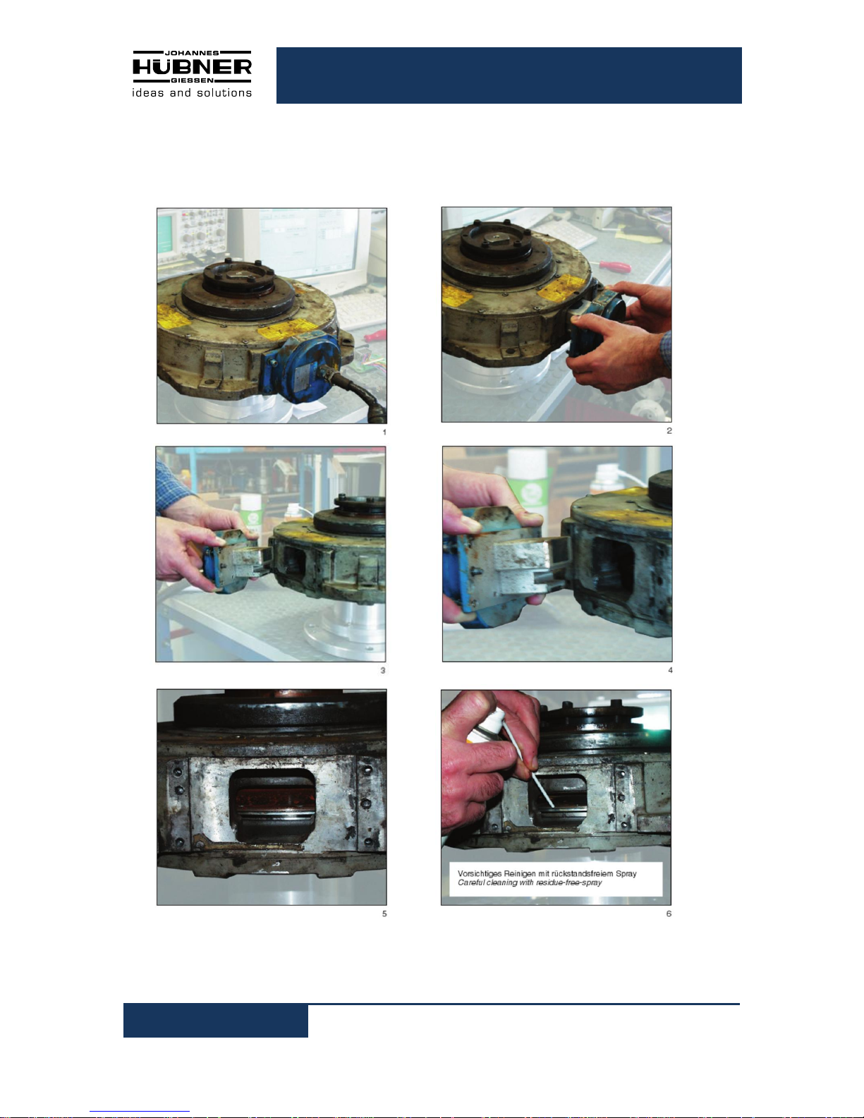
9.1 Exchange of scanning-system
of Encoder FGH 14. Easy exchange of all optical and electronic components without removal of the
encoder form motor shaft.
3. Plug-in new scanning head
New silicon seal
must be checked
E-55679
SCANNING-SYSTEM
area must be cleaned
4 x captive fastening screws
pins installed for precise adjustment
Cleaning
Careful cleaning of pulse disk
with air-pressure and / or cleaner
through access
Plug-in new scanning system
Precise adjustment – No further
alignment necessary.
1. Remove scanning head
2. Cleaning pulse disk
Incremental hollow shaft encoder FGH 14
22
FGH14_MANUAL-en_R5(2017-08-14)ID68166.doc
9.2 Pictures
Photo No. 1 to 6: Sequence of disassembly / exchange = Scanning - System

Incremental hollow shaft encoder FGH 14
FGH14_MANUAL-en_R5(2017-08-14)ID68166.doc
23
10 Disposal
10.1 Disposal procedure
The manufacturer is not obliged to take back the device.
The device is classed as electronic equipment and subject to the WEEE Directive; observe local,
country-specific laws when disposing of the device.
For information on environmentally sound disposal please contact your local authority or a specialist
disposal company.

Incremental hollow shaft encoder FGH 14
24
FGH14_MANUAL-en_R5(2017-08-14)ID68166.doc
11 EC-Declaration of Incorporation

Incremental hollow shaft encoder FGH 14
FGH14_MANUAL-en_R5(2017-08-14)ID68166.doc
25

Incremental hollow shaft encoder FGH 14
26
FGH14_MANUAL-en_R5(2017-08-14)ID68166.doc

Incremental hollow shaft encoder FGH 14
FGH14_MANUAL-en_R5(2017-08-14)ID68166.doc
27
12 Dimension drawings
FGH 14 EK / EEK…140P
HM 14 M 107307

Incremental hollow shaft encoder FGH 14
28
FGH14_MANUAL-en_R5(2017-08-14)ID68166.doc
FGH 14 EC… / 93 S
Annex with torque bracket
HM 12 M 105102

Incremental hollow shaft encoder FGH 14
FGH14_MANUAL-en_R5(2017-08-14)ID68166.doc
29
FGH 14 EC… / 150 K mod
Annex with torque bracket
HM 12 M 105099

Incremental hollow shaft encoder FGH 14
30
FGH14_MANUAL-en_R5(2017-08-14)ID68166.doc
FGH 14 EK / EEK / 108 C
taper 1:10
HM 02 M 55 614

Incremental hollow shaft encoder FGH 14
FGH14_MANUAL-en_R5(2017-08-14)ID68166.doc
31
FGH 14 EER / 148 C
HM 14 M 107830
Further dimension drawings on our Website or on request.

Incremental hollow shaft encoder FGH 14
32
FGH14_MANUAL-en_R5(2017-08-14)ID68166.doc
13 Connections
FGH 14
Standard
Terminal box
FGH 14
Standard
Connection cable

Incremental hollow shaft encoder FGH 14
FGH14_MANUAL-en_R5(2017-08-14)ID68166.doc
33
FGH 14
Standard
12 – pole Burndy plug
FGH 14
Standard
15 – pole Harting plug

Incremental hollow shaft encoder FGH 14
34
FGH14_MANUAL-en_R5(2017-08-14)ID68166.doc
FGH 14
Standard
42 pole industry plug

Incremental hollow shaft encoder FGH 14
FGH14_MANUAL-en_R5(2017-08-14)ID68166.doc
35
14 Annex
Mounting and Removal Instruction
of Incremental Hollow Shaft Encoder
Encoder TYPE: FGH 14…/ .S
Mounting Tool: with torque wrench
2010-01-04
Type: FGH 14… / .S TQ = 25 Nm or
bore: Ø 93, Ø 107,95 – Spieth clamp- TQ = 18,5 ft Ibs
bore: Ø 95 – Spieth clamp- TQ = 10 Nm
TQ = 7,5 ft Ibs
Type: FGH 14… / 150 K TQ = 50 Nm or
bore: Ø 150 TQ = 37 ft Ibs
Torque wrench of type 10-60 Nm 1/2", hexagonal
bore 6 mm
Torque wrench or type 10-60 Nm 1/2", hexagonal
bore 8 mm
Voreinstellbarer
Drehmomentschlüssel
mit eingebauter Umschaltknarre
Messung bei Rechts- und Linksgang
Pre-set Torque Wrench
with reversible ratchet
right and left side measuring
Bedienungsanleitung
1. Bitte beachten Sie eventuell empfoh-
lene Anzugswerte der Schraubenhersteller.
2. Schlüssel nur am Handgriff belasten.
3. Den Drehmomentschlüssel vor
Belastung mit vollem Anzugswert
zunächst nur mit 75% betätigen, dann
mit vollem Wert nachsetzen.
4. Schlüssel langsam und stetig steigend
belasten, keinesfalls ruckartig, da
sonst fehlerhafte Anzeige.
5. Das voreingestellte Drehmoment ist
erreicht, wenn der Schlüssel ein hörund fühlbares „KLICK“ –Signal abgibt.
6. Falls Schlüssel nicht mehr in
Gebrauch, auf kleinste Skalaanzeige
zurückstellen.
Operating instruction
1. Please, obey any recommended
tightening torques.
2. Apply torque loads only by using
the plastic handle.
3. Firstly, pre-set torque wrench at a
lower load – about 75% than
required – re-set the wrench and
tighten again.
4. Use wrench by smooth and
continuous pull to ensure more
accurate results.
5. The pre-set torque is reached as
soon as the audible and sensible
“CLICK” –Signal is noticed.
6. Reduce torque setting to its lowest
figure when the wrench is not in
use.

Incremental hollow shaft encoder FGH 14
36
FGH14_MANUAL-en_R5(2017-08-14)ID68166.doc

Incremental hollow shaft encoder FGH 14
FGH14_MANUAL-en_R5(2017-08-14)ID68166.doc
37

Incremental hollow shaft encoder FGH 14
38
FGH14_MANUAL-en_R5(2017-08-14)ID68166.doc

Incremental hollow shaft encoder FGH 14
FGH14_MANUAL-en_R5(2017-08-14)ID68166.doc
39
10 Nm (95)
7,5 ft lbs
bore: 95

Incremental hollow shaft encoder FGH 14
40
FGH14_MANUAL-en_R5(2017-08-14)ID68166.doc
 Loading...