

English
Operating and Assembly Instructions
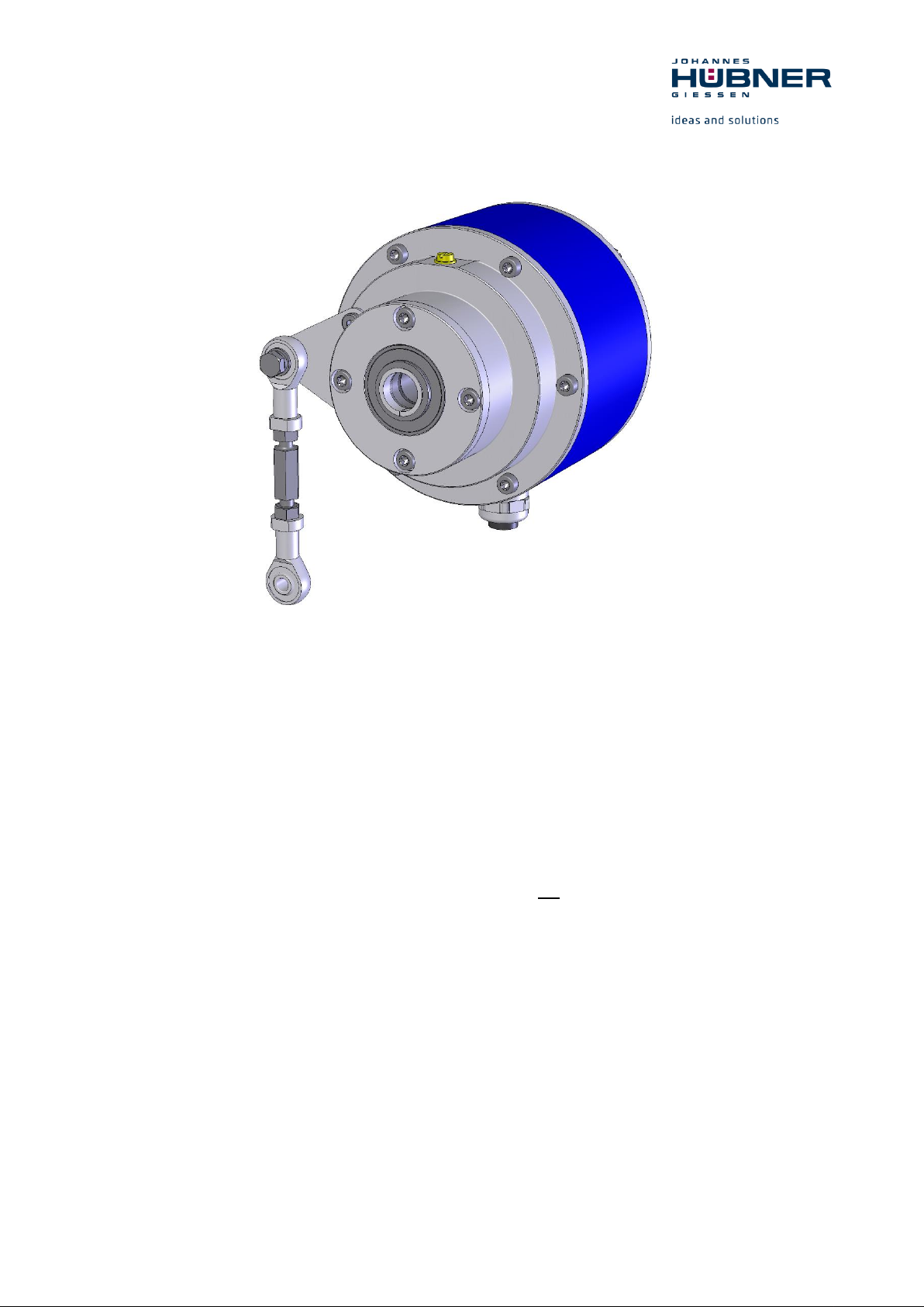
Electronic overspeed switch EGSHJ 2
Straightforward monitoring of overspeed or zero speed detection
Read the Operating and Assembly Instructions prior to
assembly, starting installation and handling!
Keep for future reference!
Translation of the original operating and assembly instructions EGSHJ2_MANUAL-en_R1(2018-11-23)ID74615.docx
ID 74615

Electronic overspeed switch EGSHJ 2
2
EGSHJ2_MANUAL-en_R1(2018-11-23)ID74615.docx
Trademark
Protected trademarks bearing a ™ or ® symbol are not always depicted as such in the manual.
However, the statutory rights of the respective owners remain unaffected.
Manufacturer / publisher
Johannes Hubner
Fabrik elektrischer Maschinen GmbH
Siemensstraße 7
35394 Giessen
Germany
Phone: +49 641 7969 0
Fax: +49 641 73645
E-Mail: info@huebner-giessen.com
www.huebner-giessen.com
The manual has been drawn up with the utmost care and attention. Nevertheless, we cannot exclude
the possibility of errors in form and content. It is strictly forbidden to reproduce this publication or parts
of this publication in any form or by any means without the prior written permission of Johannes
Hubner Fabrik elektrischer Maschinen GmbH.
Subject to errors and changes due to technical improvements.
Copyright © Johannes Hubner
Fabrik elektrischer Maschinen GmbH
All rights reserved.

Electronic overspeed switch EGSHJ 2
EGSHJ2_MANUAL-en_R1(2018-11-23)ID74615.docx
3
Directory
1 General ............................................................................................................................ 5
1.1 Information about the Operating and Assembly Instructions ....................................... 5
1.2 Scope of delivery ....................................................................................................... 5
1.3 Explanation of symbols .............................................................................................. 5
1.4 Disclaimer .................................................................................................................. 6
1.5 Copyright ................................................................................................................... 6
1.6 Guarantee terms ........................................................................................................ 6
1.7 Customer service ....................................................................................................... 6
2 Safety ............................................................................................................................... 6
2.1 Responsibility of the owner ........................................................................................ 6
2.2 Personnel ................................................................................................................... 6
2.3 Intended use .............................................................................................................. 7
2.4 Improper use .............................................................................................................. 7
2.5 Personal protective equipment ................................................................................... 7
2.6 Special dangers ......................................................................................................... 8
2.6.1 Electrical current .................................................................................................... 8
2.6.2 Rotating shafts / hot surfaces ................................................................................ 8
2.6.3 Safeguarding against restart .................................................................................. 8
3 Technical Data ................................................................................................................ 9
3.1 Type plate .................................................................................................................. 9
3.2 Type code .................................................................................................................10
3.3 Electrical and mechanical data ..................................................................................10
4 Switching speed range ..................................................................................................11
4.1 Zero speed monitoring ..............................................................................................11
5 Transport, packaging and storage ...............................................................................12
5.1 Safety instructions for transport .................................................................................12
5.2 Goods inward inspection ...........................................................................................12
5.3 Packaging / disposal .................................................................................................12
5.4 Storage of packages (devices) ..................................................................................12
6 Installation and commissioning ....................................................................................13
6.1 Safety instructions .....................................................................................................13
6.2 Technical information ................................................................................................13
6.3 Required tools ................................................................................................ ...........13
6.4 Mounting preparations ..............................................................................................14
6.5 Mounting hollow shaft type ........................................................................................14
6.6 Using the adjustable torque bracket ..........................................................................15
6.7 Shortenable torque bracket (optional) .......................................................................17
6.8 Electrical connection and start up ..............................................................................17
6.8.1 Preparing cables ..................................................................................................17

Electronic overspeed switch EGSHJ 2
4
EGSHJ2_MANUAL-en_R1(2018-11-23)ID74615.docx
6.8.2 Electrical connection .............................................................................................17
7 Dismantling ....................................................................................................................18
7.1 Safety instructions .....................................................................................................18
7.2 Dismantling the encoder ...........................................................................................18
8 Faults ..............................................................................................................................19
8.1 Faults table ...............................................................................................................19
9 Inspections .....................................................................................................................20
9.1 Safety instructions .....................................................................................................20
9.2 Maintenance information ...........................................................................................20
9.3 Inspection schedule ..................................................................................................20
10 Disposal ..........................................................................................................................20
10.1 Disposal procedure ...................................................................................................20
11 Replacement parts .........................................................................................................20
12 Dimension drawings ......................................................................................................21
13 Connection diagrams ....................................................................................................26
13.1 Terminal box .............................................................................................................26
13.2 Connection cable ......................................................................................................26
Electronic overspeed switch EGSHJ 2
EGSHJ2_MANUAL-en_R1(2018-11-23)ID74615.docx
5
WARNING!
Indicates a possibly dangerous situation that can result in death or serious injury if it is not
avoided.
CAUTION!
Indicates a possibly dangerous situation that can result in minor injury if it is not
avoided.
CAUTION!
Indicates a possibly dangerous situation that can result in material damage if it is not
avoided.
NOTES!
Indicates useful tips and recommendations as well as information for efficient and troublefree operation.
NOTES!
Do not use a hammer or similar tool when installing the device due to the risk of damage
occurring to the bearings or coupling!
DANGER!
Life-threatening danger due to electric shock!
Indicates a life-threatening situation due to electric shock. If the safety instructions are not
complied with there is danger of serious injury or death. The work that must be executed
should only be performed by a qualified electrician.
1 General
1.1 Information about the Operating and Assembly Instructions
These Operating and Assembly Instructions provide important instructions for working with the device.
They must be carefully read prior to starting all tasks, and the instructions contained herein must be
followed.
In addition, applicable local regulations for the prevention of industrial accidents and general safety
regulations must be complied with.
1.2 Scope of delivery
Electronic overspeed switch EGSHJ 2, Operating and Assembly Instructions. Fixing part according to
dimension drawing, if applicable.
1.3 Explanation of symbols
Warnings are indicated by symbols in these Operating and Assembly Instructions. The warnings are
introduced by signal words that express the scope of the hazard.
The warnings must be strictly heeded; you must act prudently to prevent accidents, personal injury, and
property damage.

Electronic overspeed switch EGSHJ 2
6
EGSHJ2_MANUAL-en_R1(2018-11-23)ID74615.docx
NOTES!
Content information, text, drawings, graphics, and other representations are protected
by copyright and are subject to commercial property rights.
It is strictly forbidden to make copies of any kind or by any means for any purpose other
than in conjunction with using the device without the prior written agreement of the
manufacturer. Any copyright infringements will be prosecuted.
DANGER!
This section provides an overview of all the important safety aspects that ensure
protection of personnel, as well as safe and trouble-free device operation.
If these safety instructions are not complied with significant hazard can occur.
1.4 Disclaimer
All information and instructions in these Operating and Assembly Instructions have been provided under
due consideration of applicable guidelines, as well as our many years of experience.
The manufacturer assumes no liability for damages due to:
Failure to follow the instructions in the Operating and Assembly Instructions
Non-intended use
Deployment of untrained personnel
Opening of the device or conversions of the device
In all other aspects the obligations agreed in the delivery contract as well as the delivery conditions of
the manufacturer apply.
1.5 Copyright
1.6 Guarantee terms
The guarantee terms are provided in the manufacturer’s terms and conditions.
1.7 Customer service
For technical information personnel is available that can be contacted by telephone, fax or email. See
manufacturer’s address on page 2.
2 Safety
2.1 Responsibility of the owner
The device is used in commercial applications. Consequently the owner of the device is subject to the
legal occupational safety obligations and subject to the safety, accident prevention and environmental
protection regulations that are applicable for the device’s area of implementation.
2.2 Personnel
Installation and commissioning as well as disassembly routines must be carried out by skilled technical
staff only.

Electronic overspeed switch EGSHJ 2
EGSHJ2_MANUAL-en_R1(2018-11-23)ID74615.docx
7
2.3 Intended use
The device has been designed and constructed exclusively for the intended use described here.
Series EGSHJ 2 electronic overspeed switches are used for speed monitoring, for instance of electrical
and mechanical drives, hoisting gear, and conveying machines.
The electronic overspeed switch EGSHJ 2 is a overspeed switch, which generates a switching signal
for a superior control system. This is realized with opening of a switch contact. As an alternative to this
function, the device can also be used for zero speed detection. Not in addition.
Claims of any type due to damage arising from non-intended use are excluded; the owner bears sole
responsibility for non-intended use.
2.4 Improper use
Do not use the device in potentially explosive areas.
The device must not be subjected to mechanical loads in addition to its own weight and unavoidable
vibration and shock loads that arise during normal operations.
Examples for non-permitted mechanical loads (incomplete list):
Fastening transport or lifting tackle to the device, for example a crane hook to lift a motor.
Fastening packaging components to the device, for example ratchet straps, tarpaulins etc.
Using the device as a step, for example by people to climb onto a motor.
2.5 Personal protective equipment
For tasks such as assembly, disassembly or commissioning the use of personal protective equipment
such as safety footwear and protective work clothing is required.
The regulations specified by the owner and that are locally specified apply.

Electronic overspeed switch EGSHJ 2
8
EGSHJ2_MANUAL-en_R1(2018-11-23)ID74615.docx
DANGER!
Life-threatening danger due to electrical shock!
There is an imminent life-threatening hazard if live parts are touched. Damage to
insulation or to specific components can pose a life-threatening hazard.
Therefore:
Immediately switch off the device and have it repaired if there is damage to the insulation
of the power supply.
De-energize the electrical equipment and ensure that all components are connected for
all tasks on the electrical equipment.
Keep moisture away from live parts. Moisture can cause short circuits.
WARNING!
Danger of injury due to rotating shafts and hot surfaces!
Touching rotating shafts can cause serious injuries.
Therefore:
Do not reach into moving parts/shafts or handle moving parts/shafts during operation.
Close to protect from injury all access openings in flanges with the corresponding plug
screw, and provided you exposed rotating components with protective covers.
Do not open covers during operation. Prior to opening the covers ensure that all parts
have come to a zero speed.
The encoder can become hot during prolonged use.
In case of contact risk of burns is existing.
DANGER!
Life-threatening danger if restarted without authorization!
When correcting faults there is danger of the power supply being switched on without
authorization.
This poses a life-threatening hazard for persons in the danger zone.
Therefore:
Prior to starting work, switch off the system and safeguard it from being switched on again.
2.6 Special dangers
Residual risks that have been determined based on a risk assessment are cited below.
2.6.1 Electrical current
2.6.2 Rotating shafts / hot surfaces
2.6.3 Safeguarding against restart

Electronic overspeed switch EGSHJ 2
EGSHJ2_MANUAL-en_R1(2018-11-23)ID74615.docx
9
Englisch
Deutsch
Manufacturer, address
Hersteller, Anschrift
Type: Overspeed switch
Typ: Grenzdrehzahlschalter
Year of manufacture
Baujahr
Item (ID)
Artikel (ID)
CE mark
CE-Kennzeichnung
Serial number (S/N)
Seriennummer (S/N)
Degree of protection
Schutzart
Supply voltage
Versorgungsspannung
Max. speed
Max. Drehzahl
release speed
Schaltdrehzahl
Output capacity
Schaltspannung / Schaltstrom
3 Technical Data
3.1 Type plate
Type plate example:
The type plate is located on the outside of the housing and contains the following information:

Electronic overspeed switch EGSHJ 2
10
EGSHJ2_MANUAL-en_R1(2018-11-23)ID74615.docx
EGS(HJ)
2
AK
16K
Electronic overspeed switch
H: (hollow shaft design)
HJ: (hollow shaft design with isolated bearings)
Series
Connection
AK = Axial terminal box
12K: Hollow shaft Ø 12 H7 mm with clamping solution
16K: Hollow shaft Ø 16 H7 mm with clamping solution
17C: Hollow shaft Ø 17 mm with conical shaft 1:10
R75: Hollow shaft Ø 0,75”
Connection data
Supply voltage
12 … 30 VDC, max. 50 mA
Release voltage, current
max. 30 VDC/max. 0,5 A
Connection
Spring-cage terminal strip type Phoenix ZFKDS 1,5-W-5,08
(0,25 mm² - 1,5 mm²)
Device temperature range
-25°C … + 85°C
Degree of protection acc.DIN EN
60529
Sealing
Rotor moment of
inertia
Breakaway
torque Ncm
IP 66
Labyrinth sealing
approx. 315 gcm²
approx. 3,5 - 4
Vibration resistance
DIN EN 60068-2-6 / IEC 68-2-6 (10 … 2000 Hz)
20 g (=200 m/s²)
Shock resistance
DIN EN 60068-2-27 / IEC 68-2-27 (6 ms)
200 g (=2000 m/s²)
Max. permissible. speed:
6000 rpm
Weight
approx. 2 kg
3.2 Type code
3.3 Electrical and mechanical data

Electronic overspeed switch EGSHJ 2
EGSHJ2_MANUAL-en_R1(2018-11-23)ID74615.docx
11
Specification
Value
Switching speed range, factory-set
AK with hollow shaft max. 5400 rpm
Deviation from switch:
Accuracy of measurement: 2%
Switching time TSw :<3ms
Switch data
0…30 VDC/max 500mA
Max. voltage drop at closed switch: 0,7V
Rotation speed n
[rpm]
State
Switching contact
n = 0
(zero speed)
n ≥ 0,25
(rotary motion)
0 < n < 0,25
(creep motion)
switching contact opens for
approx. 200 - 400 milliseconds
after a change in the angular
position of ± 5°
4 Switching speed range
The electronic overspeed switch EGSHJ 2 has a galvanically insulated switching output. The switching
function is realized with a semiconductor, the switching speed is set in our factory (switching
hysteresis 10%). Possible value for switching speed is any whole number between 1 and 5400 rpm.
If the set switching speed is exceeded, the switch opens.
It is recommended to save the switch circuit against an overcurrent with a fuse (0,5A).
4.1 Zero speed monitoring
The zero speed monitoring is a function for the control of rotary movements. This function is available
as an alternative to overspeed monitoring, not in addition. The galvanically isolated switching contact
changes the state as soon as the shaft leaves the zero speed.
Functionality:
At a speed of less than 0.25 rpm the zero speed monitoring is activated and the switching contacting
contact is closed. When the zero speed monitoring is activated, the current position value is stored
and monitored for possible changes in the angle of rotation. As a result, very slow or creeping wave
movements can also be detected. In the speed range from 0 to 0.25 rpm, the switching contact opens
for approx. 200 - 400 milliseconds after a change in the angular position of ± 5 °. The possible
switching contact states are shown in the following table.
The switching contact is closed at zero speed (n = 0 rpm).
For rotary movement (n ≥ 0.25 rpm), the switching contact is open.
At a creep motion (0 <n <0.25 rpm), the switching contact opens as soon as a change in the angle of
rotation of more than ± 5 °. After 200 to 400 ms, the switching contact is closed again as long as the
speed is less than 0.25 rpm.

Electronic overspeed switch EGSHJ 2
12
EGSHJ2_MANUAL-en_R1(2018-11-23)ID74615.docx
CAUTION!
Material damage caused by improper transport!
Observe the symbols and information on the packaging:
Do not throw - risk of breakage
Keep dry
Do not expose to heat above 40 °C or direct sunlight.
Keep dry
Keep packages dry and free from dust; protect from moisture.
Protect against heat
Protect packages from heat above 40 °C and direct sunlight.
NOTES!
Turn the shaft of the device every 6 month to prevent the bearing grease solidifying!
5 Transport, packaging and storage
5.1 Safety instructions for transport
5.2 Goods inward inspection
Check the delivery immediately upon receipt for transit damage or short delivery.
Inform the carrier immediately on receipt if you determine that damage has occurred during transit (take
photos as proof).
5.3 Packaging / disposal
The packaging is not taken back and must be disposed of in accordance with the respective statutory
regulations and local guidelines.
5.4 Storage of packages (devices)
If you intend to store the device for a longer period of time (> 6 months) we recommend you use
protective packaging (with desiccant).

Electronic overspeed switch EGSHJ 2
EGSHJ2_MANUAL-en_R1(2018-11-23)ID74615.docx
13
WARNING!
Observe the safety instructions contained in Chapter 2 when dismantling the device!
NOTES!
Do not use a hammer or similar tool when installing the device due to the risk of damage
occurring to the bearings or coupling!
6 Installation and commissioning
6.1 Safety instructions
Personnel
Installation and commissioning must be carried out by skilled technical staff only.
6.2 Technical information
Ambient temperature
The max. permissible ambient temperature depends on the speed and degree of protection of the
device, the signal frequency, the length of the signal cable and the place of installation (please refer to
Chapter 3.3).
Degree of protection
To fulfil degree of protection requirements the diameter of the connection cable must correspond to that
of the cable gland (please refer to Chapter 12 Dimension drawings)!
Deep groove ball bearings
EGS 2 overspeed switches are fitted with maintenance-free, greased "for-life" deep groove bearings.
Bearings must be changed by the manufacturer only. Opening the encoder renders the guarantee null
and void.
Screw retention
We recommend using Loctite® 243 threadlocker (medium strength) on all fastening screws to prevent
loosening.
6.3 Required tools
Spanners: 10 mm, 12 mm, 22 mm (e.g. DIN 894)
Allen keys: 2 mm, 3 mm, 5 mm, 6 mm
Flat-blade screwdrivers:
Assembly grease
Loctite® 243 (medium strength threadlocker)

Electronic overspeed switch EGSHJ 2
14
EGSHJ2_MANUAL-en_R1(2018-11-23)ID74615.docx
NOTES!
Fastening screws and earth cable are not included in the range of supply.
NOTES!
The maximum radial run-out of the adapter shaft/motor shaft should not exceed 0,2 mm.
We recommend a radial deviation of 0,03 mm.
If necessary, use the ball thrust adjustment screw to align the adapter shaft. Secure ball
thrust screws with Loctite® 243. Remove unused ball thrust screws or secure with Loctite®
243. Max. tightening torque for M12 approx. 25 Nm, for M16 approx. 35 Nm.
Use parallel keys to DIN 6885.
Please also observe the supplement data sheet Mounting accuracy for hollow shaft
encoders.
You should also observe the Installation instructions supplied with the adapter shaft when
installing!
Figure 1
4 3 2
1
5 9 8
10
11 6 7
6.4 Mounting preparations
1. Ensure all accessories are available (please refer to Chapter 12 Dimension drawings).
2. Preparing the place of attachment: Clean the (motor) shaft, centering, bolting surfaces and fastening
threads; check for damage. Repair any damage!
6.5 Mounting hollow shaft type
1. Mount adapter shaft (1) and align using dial gauge.

Electronic overspeed switch EGSHJ 2
EGSHJ2_MANUAL-en_R1(2018-11-23)ID74615.docx
15
NOTES!
The cap screws have a coating with micro-encapsulated adhesive for securing screws. If
screws are used without micro-adhesive coating the screws are with
Loctite® 243 to be secured.
NOTES!
Once fitted the link rod must rotate easily around the link rod heads! Failure to observe
this point may result in damage to the bearings!
NOTES!
The link heads are maintenance free. However, ensure they remain free from soiling
and paint!
Number
ID Number
Minimum length
(mm)
Maximum length
(mm)
1
21402
141
180
2
21403
180
250
3
21404
250
350
2. Lightly grease the adapter shaft, open the device.
3. Slide the circular spring device (2) onto the adapter shaft until it stops.
4. Mount the hollow shaft device (3) to the adapter shaft.
The hollow shaft encoder must slide smoothly on to the adapter shaft. In no delay with increased
force, otherwise the bearing may be damaged. Where appropriate adapter shaft with emery cloth
rework. The hollow shaft encoder does not strike hard against the shaft shoulder.
5. Secure the hollow shaft device with the aid of the hexagon socket head cap screw (4).
(Fig.1) maximum tightening 6 Nm.
6. Close the hollow shaft device with cover (5) and 4 screws (6).
7. Fastening the torque bracket:
Bolt the link rod (8) with screw (9), washer and nut with torque bracket (10).
The ideal angle of torque bracket (10) to the link rod (8) is 90°.
Secure the link heads (11) of the link rod to a fixed point (for example on the motor housing).
6.6 Using the adjustable torque bracket
The torque bracket is supplied completely screwed together. To adjust the length of the torque
bracket, release the interlocked nuts. Turn the rigging screw to the left or to the right to adjust the
torque bracket to the required length. Then tighten the hex nuts to lock the adjusted length.

Electronic overspeed switch EGSHJ 2
16
EGSHJ2_MANUAL-en_R1(2018-11-23)ID74615.docx
Number 1
min. length in mm
Number 1
max. length in mm
Number 2
min. length in mm
Number 2
max. length in mm
Number 3
min. length in mm
Number 3
max. length in mm

Electronic overspeed switch EGSHJ 2
EGSHJ2_MANUAL-en_R1(2018-11-23)ID74615.docx
17
Type
ID Number
Min. length (mm)
Max. length (mm)
D
21975
71
390
E
22057
71
430
NOTES!
You must observe applicable EMC guidelines when routing cables!
CAUTION!
Do not allow moisture to enter the terminal box when the cover is open!
NOTES!
Prior to delivery cable glands and blanking plugs are tightened finger tight only. To ensure
that the terminal box is reliably sealed tighten all cable glands and blanking plugs before
starting up for the first time.
NOTES!
Prevent lateral pulling forces acting on the cable so as not to impair the degree of
protection of the cable gland.
6.7 Shortenable torque bracket (optional)
The torque arms in the table below can be shortened by the customer.
See dimension drawing HM 13 M 106952a Chapter 12.
6.8 Electrical connection and start up
6.8.1 Preparing cables
1. Strip cable insulation.
2. Crimp wire-end ferrules.
6.8.2 Electrical connection
1. Open the terminal box cover (15, Fig.1).
2. Remove the cap of the cable gland (7, Fig.1).
3. Feed the cable into the terminal box trough the cable gland.
4. Tighten the cable gland using a spanner.
5. Use a spanner to tighten the cable gland until the cables are securely clamped and properly
sealed.

Electronic overspeed switch EGSHJ 2
18
EGSHJ2_MANUAL-en_R1(2018-11-23)ID74615.docx
NOTES!
Before closing the terminal box cover check and if necessary clean both seal surfaces
and the gasket.
CAUTION!
Ensure when closing the terminal box cover that no cable becomes jammed.
WARNING!
Observe the safety instructions contained in Chapter 2 when dismantling the device!
NOTES!
Do not use a hammer or similar tool when dismantling the device due to the risk of damage
occurring to the bearings or coupling!
!
6. Connect the supply voltage, and the signal cable (please refer to the connection diagrams,
Chapter 13).
7. Close the terminal box cover.
7 Dismantling
7.1 Safety instructions
Personnel
Dismantling must be carried out by skilled technical staff only.
7.2 Dismantling the encoder
Disconnect all electrical cable prior to beginning any work.
To dismantling the device follow the instructions given in Chapter 6.5 in the reverse order. For
dismounting first a threaded pin M6x10 ISO 7436 has to be screwed into the adapter shaft. With a screw
M8, the device must be pressed. Optionally, the adapter shaft must be secured against turning

Electronic overspeed switch EGSHJ 2
EGSHJ2_MANUAL-en_R1(2018-11-23)ID74615.docx
19
Faults
Possible cause
Remedy
Switch does not close
No supply voltage
Control: LED in the terminal box
does not shine
Check connection cable and
supply voltage
Error LED does not shine:
Rotation speed above the
switching speed
Adjust the suitable rotation
speed
Error LED is shining:
Evaluation of rotation speed is
faulty.
Disconnect power supply and
switch on again
Moisture in the terminal box
Soiled terminal box gasket or
seal surfaces
Clean terminal box gasket and
seal surfaces
Damaged terminal box gasket
Replace terminal box gasket
Cable gland/blanking plug not
tightened
Tighten cable gland/blanking
plug
Unsuitable cable for cable gland
Use suitable cable and cable
glands
Contact Hubner-Service (page 2) if none of the remedies listed above provides a solution!
8 Faults
8.1 Faults table

Electronic overspeed switch EGSHJ 2
20
EGSHJ2_MANUAL-en_R1(2018-11-23)ID74615.docx
WARNING!
Skilled technical staff only are permitted to inspect the device and its installation.
Observe the safety instructions contained in Chapter 2 when inspecting or working on
the device!
Interval
Inspections
Yearly
Ensure the fastening screws are properly tightened
Ensure cable connections and connection terminals are
securely seated
Check the torque bracket
Following approx 16 000 – 20 000
hours of operation / higher levels
of continuous load
Check deep groove ball bearings are running smoothly and
listen for running noises. Bearings must be replaced by the
manufacturer only.
Replacement parts
Comment
Cable gland
M 20 x 1.5, cable Ø 5…14 mm
Terminal box cover
Including O-Ring and screws
9 Inspections
9.1 Safety instructions
9.2 Maintenance information
The device is maintenance-free. However, to guarantee optimum fault-free operations we recommend
that you carry out the following inspections.
9.3 Inspection schedule
10 Disposal
10.1 Disposal procedure
The manufacturer is not obliged to take back the device.
The device is classed as electronic equipment; observe local country-specific laws when disposing of
the device.
For information on environmentally sound disposal please contact your local authority or a specialist
disposal company.
11 Replacement parts
The replacement parts listed below can be obtained via the service address on page 2.

Electronic overspeed switch EGSHJ 2
EGSHJ2_MANUAL-en_R1(2018-11-23)ID74615.docx
21
12 Dimension drawings

Electronic overspeed switch EGSHJ 2
22
EGSHJ2_MANUAL-en_R1(2018-11-23)ID74615.docx

Electronic overspeed switch EGSHJ 2
EGSHJ2_MANUAL-en_R1(2018-11-23)ID74615.docx
23

Electronic overspeed switch EGSHJ 2
24
EGSHJ2_MANUAL-en_R1(2018-11-23)ID74615.docx

Electronic overspeed switch EGSHJ 2
EGSHJ2_MANUAL-en_R1(2018-11-23)ID74615.docx
25

Electronic overspeed switch EGSHJ 2
26
EGSHJ2_MANUAL-en_R1(2018-11-23)ID74615.docx
NOTES!
The connection diagrams are displayed in each terminal box cover!
Connection diagram PN166-480a
NOTES!
The connection diagrams are attached to each cable!
Connection diagram PN166-481a
13 Connection diagrams
13.1 Terminal box
13.2 Connection cable
 Loading...