

Hubner U-ONE-SAFETY Compact USC 42, U-ONE-Compact UOC40, ECU C, ERC40, ERC C-R Configuration Instructions
...
English
Translation of the original configuration
manual
issued
August 2018
ID 74237
Configuration manual
U-ONE® -SAFETY-Compact USC 42
Universal-Encoder-System
For the following modules:
SCU-C (Safety Control Unit)
SRC C-R (Safety position switch)
SGS C-R (Safety overspeed switch)
Read the configuration manual prior to assembly,
starting installation and handling!
Keep for future reference!

U-ONE®-SAFETY Compact
Configuration manual SCU C / SRC C / SGS C
2
USC42_SCU-KonfigManual-en_R5
Trademark
Brand names and product names are trademarks or registered trademarks of their respective
owner.
Protected trademarks bearing a ™ or ® symbol are not always depicted as such in the manual.
However, the statutory rights of the respective owners remain unaffected.
Manufacturer / publisher
Johannes Hubner
Fabrik elektrischer Maschinen GmbH
Siemensstraße 7
35394 Giessen
Germany
Phone: +49 641 7969 0
Fax: +49 641 73645
Internet: www.huebner-giessen.com
E-Mail: info@huebner-giessen.com
The manual has been drawn up with the utmost care and attention. Nevertheless, we cannot
exclude the possibility of errors in form and content. It is strictly forbidden to reproduce this
publication or parts of this publication in any form or by any means without the prior written
permission of
Johannes Hubner Fabrik elektrischer Maschinen GmbH.
Subject to errors and changes due to technical improvements.
Copyright © Johannes Hubner Fabrik elektrischer Maschinen GmbH.
All rights reserved.

U-ONE®-SAFETY Compact
Configuration manual SCU C / SRC C / SGS C
USC42_SCU-KonfigManual-en_R5
3
Table of contents
1 Generally ......................................................................................................................... 5
1.1 Abbreviations and terminology used .......................................................................... 5
1.2 System requirements ................................................................................................. 5
2 Installing the software .................................................................................................... 5
2.1 Installing the driver manually ...................................................................................... 6
2.2 Manual driver installation under Windows XP SP3 ..................................................... 7
3 Setting up USC 42 ........................................................................................................... 8
3.1 Planning ..................................................................................................................... 8
4 Software description US42Pro ....................................................................................... 9
4.1 Fundamental procedure ............................................................................................. 9
4.1.1 User interface head section ................................................................................................. 10
4.1.2 Pulldown menu: File Import Parameters ......................................................................... 10
4.1.3 Pulldown menu: File Export Parameters ........................................................................ 10
4.1.4 Pulldown menu: File Report ............................................................................................ 10
4.1.5 Pulldown menu: File Offline ............................................................................................ 11
4.1.6 Pulldown menu: Options Language ................................................................................. 11
4.1.7 Pulldown menu: Options Login ........................................................................................ 11
4.1.8 Pulldown menu: Options Change password .................................................................... 11
4.1.9 Pulldown menu: Options firmware update ...................................................................... 12
4.1.10 Pulldown menu: Options Reset to factory settings .................................................... 13
4.1.11 Pulldown menu: Options Recover password ............................................................. 13
4.1.12 Pulldown menu: Options FitCalc ................................................................................ 14
4.1.13 Pulldown menu: Options Determine calibration factor ............................................... 14
4.1.14 Pulldown menu: “Analysis” switch test ...................................................................... 14
4.1.15 Pulldown menu „?“ ......................................................................................................... 15
4.1.16 Generate support file ..................................................................................................... 15
4.1.17 Display calibration settings ............................................................................................ 15
4.1.18 Display device data........................................................................................................ 15
4.1.19 Fault memory ................................................................................................................. 16
4.2 User interface - display section .................................................................................16
5 Configuring USC 42 .......................................................................................................17
5.1 Launching the software US42Pro ..............................................................................17
5.2 Operating mode ........................................................................................................17
5.2.1 Speed mode ........................................................................................................................ 17
5.2.2 Position and speed mode .................................................................................................... 17
5.3 Calibrating the position system .................................................................................18
5.3.1 Calibration ............................................................................................................................ 19
5.3.2 Determining the calibration factor with two calibration points ............................................. 19
5.3.3 Determining the calibration factor by calculation ................................................................. 19
5.4 Saving configuration- or parameterisation data in the USC 42 ..................................20
6 Functions .......................................................................................................................21
6.1 SCU C module ..........................................................................................................21
6.1.1 Digital inputs ........................................................................................................................ 21
6.1.2 Digital outputs ...................................................................................................................... 22
6.1.3 Current output (non safety related) ..................................................................................... 23
6.1.4 Configuring the incremental output (non safety-related) ..................................................... 23
6.2 SRC C module ..........................................................................................................24
6.2.1 Depiction in the display section ........................................................................................... 25
6.3 SGS C module ..........................................................................................................25
6.3.1 Underspeed ......................................................................................................................... 26

U-ONE®-SAFETY Compact
Configuration manual SCU C / SRC C / SGS C
4
USC42_SCU-KonfigManual-en_R5
6.3.2 Rotation direction dependent............................................................................................... 26
6.3.3 Switching delay .................................................................................................................... 27
6.3.4 Display in the display area ................................................................................................... 27
6.4 Input accuracy of switching points .............................................................................27
6.5 Error handling ...........................................................................................................28
6.5.1 Error table ............................................................................................................................ 29
U-ONE®-SAFETY Compact
Configuration manual SCU C / SRC C / SGS C
USC42_SCU-KonfigManual-en_R5
5
1 Generally
The U-ONE®-SAFETY-Compact is referred to as “USC 42” in the following documentation.
This document explains how to set the parameters of the U-ONE®-SAFETY-Compact using
the software US42Pro and then transfer the settings to the device.
1.1 Abbreviations and terminology used
USC 42 U-ONE®-SAFETY-Compact universal encoder system
SCU C Module Safety Control Unit
SRC C-R Module safe position switch with positively driven contacts
SGS C-R Module safe speed switch with positively driven contacts
1.2 System requirements
For configuration purposes it is possible to use any commercially available Windows® notebooks/PCs that fulfil the following system requirements:
• Windows® XP SP3 / Vista / 7 / 8 / 8.1 / 10
• Free space on the HDD: 150 MB (+ Dot Net Framework)
• Available USB 2.0 port
• 1 GB RAM, CPU: 1GHz, screen resolution 1024 x 768
2 Installing the software
Ensure the device and your notebook/PC are connected via the USB cable.
Close the automatically started „Found new hardware wizard“ with a click on “Cancel“.
Place the supplied CD containing the software into the CD drive or, alternatively, download
the Setup.exe. If the Setup.exe does not run automatically, navigate via Explorer on the CDROM drive and there start the Setup.exe.
1. The Setup guides you through the installation. Please follow the instructions on the
monitor.
If you use Windows XP, Vista or 7, continue with step 2, users higher operating system versions go on to step 3.
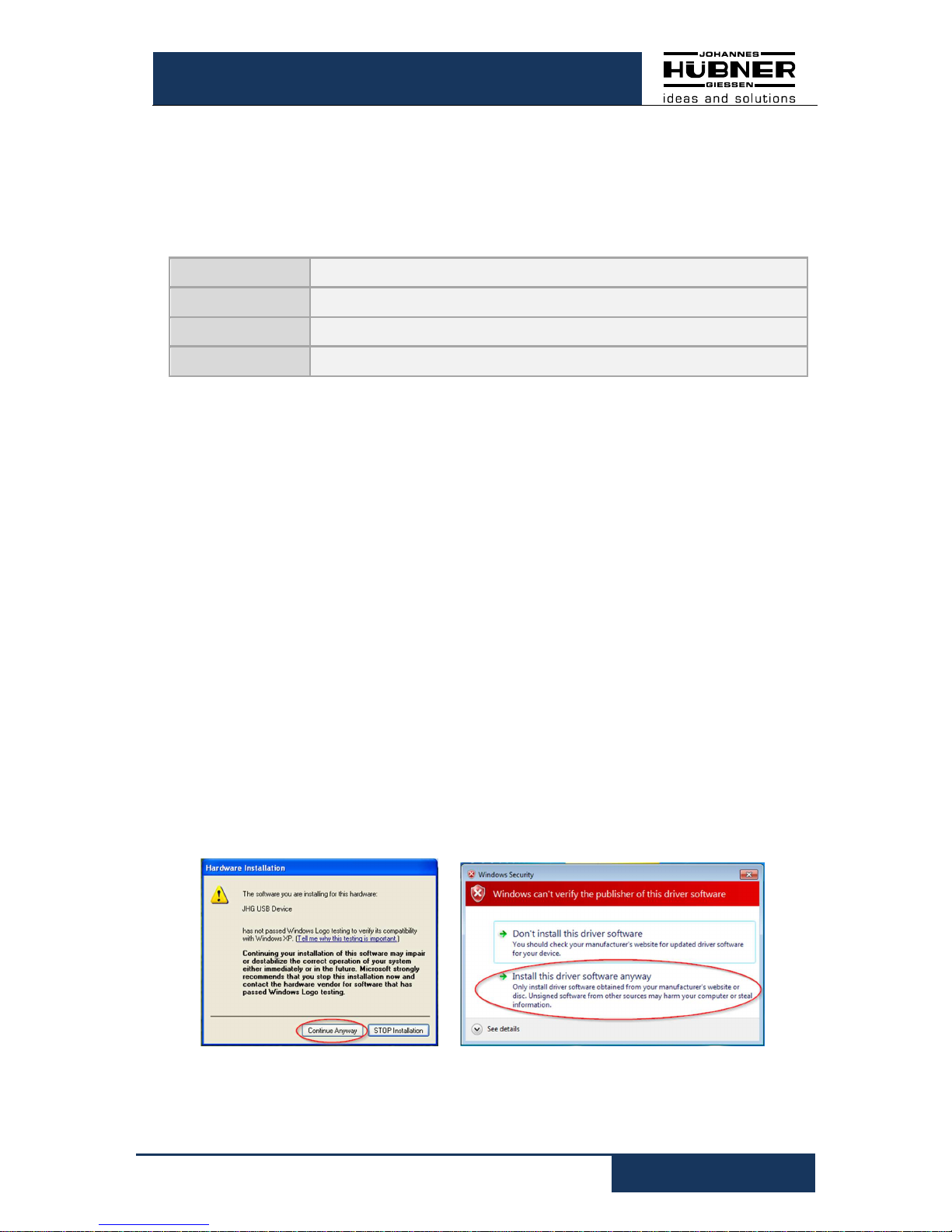
2. Windows XP SP3/ Vista / 7
Due to the ended support for your operating system, it is no longer possible for us to
sign the driver; therefore you need to confirm the installation manually. To do this, in
Windows XP, click on “ Continue Anyway ”. In Windows Vista and 7 click on “ Install
this driver software anyway ”. After that, the setup routine will continue.
3. Completion
The software has been installed and starts automatically.
Fig. 2-1: Software Installation 1

U-ONE®-SAFETY Compact
Configuration manual SCU C / SRC C / SGS C
6
USC42_SCU-KonfigManual-en_R5
2.1 Installing the driver manually
PLEASE NOTE!
You must log into a user account with administrator rights to install the software.
Ensure all programs are closed.
If it is necessary to install the driver manually, depending on your operating system, please
check the following steps.
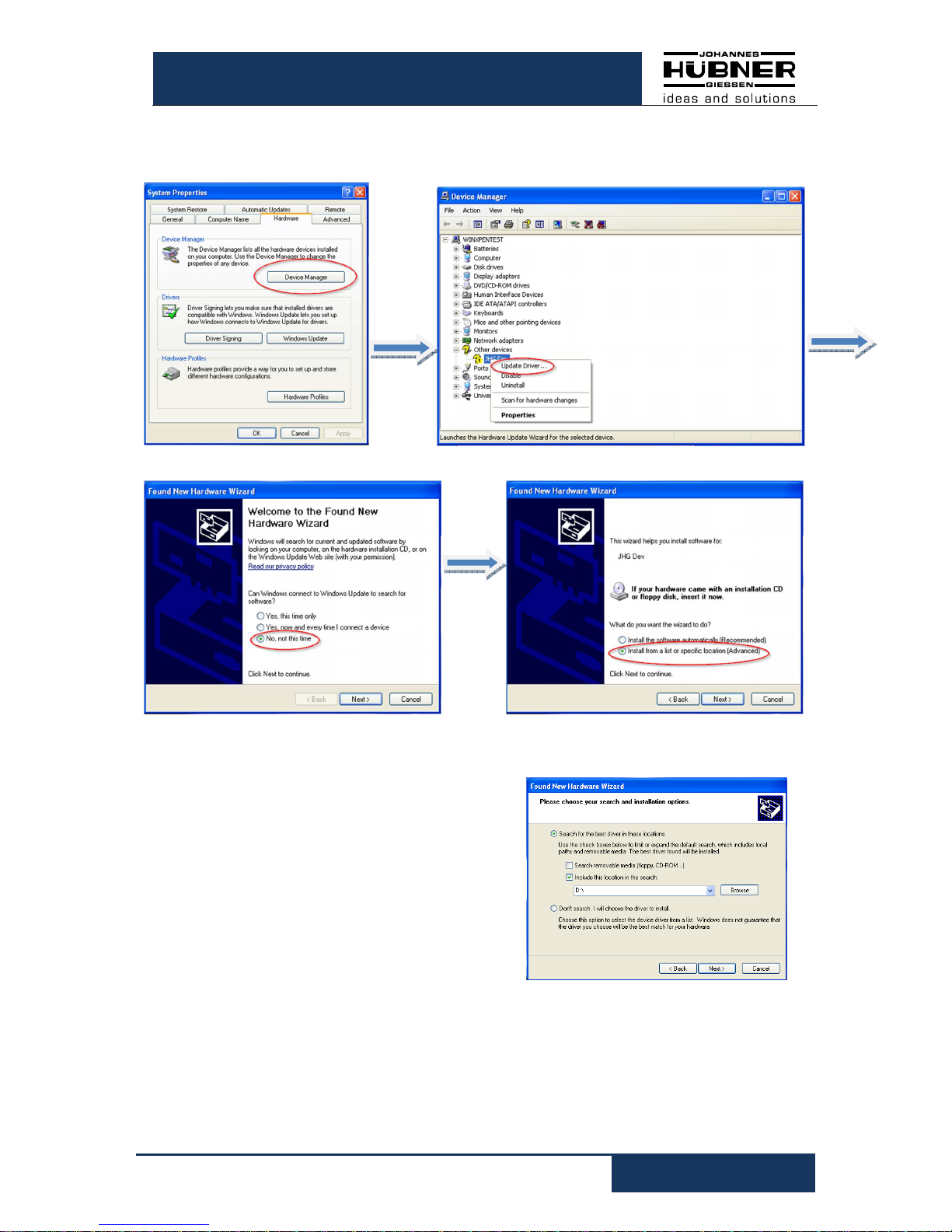
Connect the supplied USB cable with the USC 42 device and your notebook/PC
By pressing “Windows key” “Pause/Break” or desktop “Computer” (right click) “Properties”
you get into the System Properties.
Open the device manager, which lists all the connected devices. Select “JHG Dev” (right
click) “Update Driver”.
Now select the installation source via “Browse” and point to path of your installation, there
select the folder drivers. The Installation begins with a click on Next.
Click Next, the installation of the driver
software for the USC 42device has been
completed.
Finish the installation with “close”.
The USC 42device is now ready to be used.
Fig. 2-2: Driver software Installation 2
Fig. 2-3: Driver software Installation 3
U-ONE®-SAFETY Compact
Configuration manual SCU C / SRC C / SGS C
USC42_SCU-KonfigManual-en_R5
7
2.2 Manual driver installation under Windows XP SP3
Now select the installation source via “Browse” and point to path of your installation, there
select the folder drivers. The Installation begins with
a click on Next.
Click Next, the installation of the driver software for
the USC 42device has been completed.
Finish the installation with “close”.
The USC 42device is now ready to be used.
Fig. 2-4: Software Installation XP SP3
Fig. 2-5: Driver Software Installation XP SP3
U-ONE®-SAFETY Compact
Configuration manual SCU C / SRC C / SGS C
8
USC42_SCU-KonfigManual-en_R5
3 Setting up USC 42
Allow sufficient time to plan the integration and configuration of the USC 42. Please remember that planning and configuration errors can put people at risk. Put organizational
measures in place to guarantee the safe systemstate during configuration procedures!
Ensure that the system cannot enter any dangerous states during the configuration procedures including in that part of the system monitored by devices connected to the USC 42.
To configure the USC 42 you require the following:
• Operating-and configuring instructions belonging to the USC 42
• Notebook/PC running a Windows® operating system
• The configuration software US42Pro (administrator rights are required to install the
software)
• USB-Connecting cable to connect the notebook/PC with the USC 42
3.1 Planning
Caution!
Ensure you have planned the application thoroughly before you begin to configure the USC 42!
Amongst other considerations the planning must include:
• A detailed safety analysis of the planned application
• A complete list of all required devices, their connections as well as the signals and
switching points provided or required by USC 42.
In addition, the following conditions must be fulfilled:
• The USC 42 must be connected to the power supply.
• The components must be electrically connected to the USC 42.
Read also the appropriate operating and assembly instructions.
U-ONE®-SAFETY Compact
Configuration manual SCU C / SRC C / SGS C
USC42_SCU-KonfigManual-en_R5
9
4 Software description US42Pro
In this chapter you will learn how to configure the USC 42in its respective device combination
using the configuration software US42Pro. For the purpose of clarity the user interface is
divided up into different sections.
The drawing below offers a schematic overview:
Head section
Display section Configuration section
Head section:
This is where the elements used to control
the software are displayed (see Chapter
4.1.1).
Display section:
The display section is always visible and is
used to show the available modules and their
status. (See chapter 6.2.1).
In the upper section the current speed, the
current position and the optional analog output current is displayed.
Configuration section:
This is where the module parameters are
entered on the tab pages (see chapter 5).
4.1 Fundamental procedure
The USC 42 is configured by taking the following steps:
1. Turn on the notebook/PC
2. Connect the USC 42 to the USB port of the notebook/PC
3. Switch on the USC 42
4. Launch the software US42Pro and set up connection (see chapter 5.1)
5. Establish communications and log onto the USC 42 (see chapter 4.1.6)
6. Configure USC 42 (see chapter 5).
7. Check parameter settings
8. Approve the parameters in the USC 42
9. Test the parameter settings of the USC 42 on a secured system
The USC 42 is ready for operations after completing these steps.
Fig. 4-1:
schematic overview of the
user inter-
face
U-ONE®-SAFETY Compact
Configuration manual SCU C / SRC C / SGS C
10
USC42_SCU-KonfigManual-en_R5
4.1.1 User interface head section
The menu bar containing basic commands to operate the software is located in the head
section.
4.1.2 Pulldown menu: File Import Parameters
• To check the content of saved parameter sets when the device is
not connected click “Import Parameters”.
• When the device is connected it is possible to load parameters
into the input masks that were saved using the “Export
Parameters” function.
• When the device is connected and the user signed in, it is
possible to save imported parameters to the device.
4.1.3 Pulldown menu: File Export Parameters
To save device parameters to a notebook/PC click “Export Parameters”.
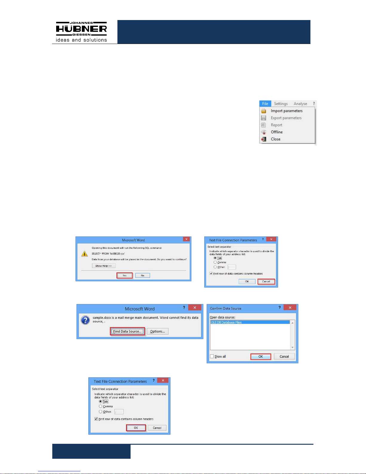
4.1.4 Pulldown menu: File Report
Click “Report” to save device parameters to a CSV file.
Using the Form Letter function in Word (for example, Word 2013) it is possible to save
device parameters for documentation purposes in Word templates as follows:
1. Open the associated template file for the device (for example,
USC 42_ReportDDA_Rx.dotx). Then select the (successive) buttons framed in red.
2. Open the previously saved “CSV file”.
3. Click OK 2x to confirm
The parameters have been saved
to the
template. You can make any changes
you like to the template. Using the Word
function “Insert Merge Field” it is possible to add more parameters.
Fig.
4-2
: File
U-ONE®-SAFETY Compact
Configuration manual SCU C / SRC C / SGS C
USC42_SCU-KonfigManual-en_R5
11
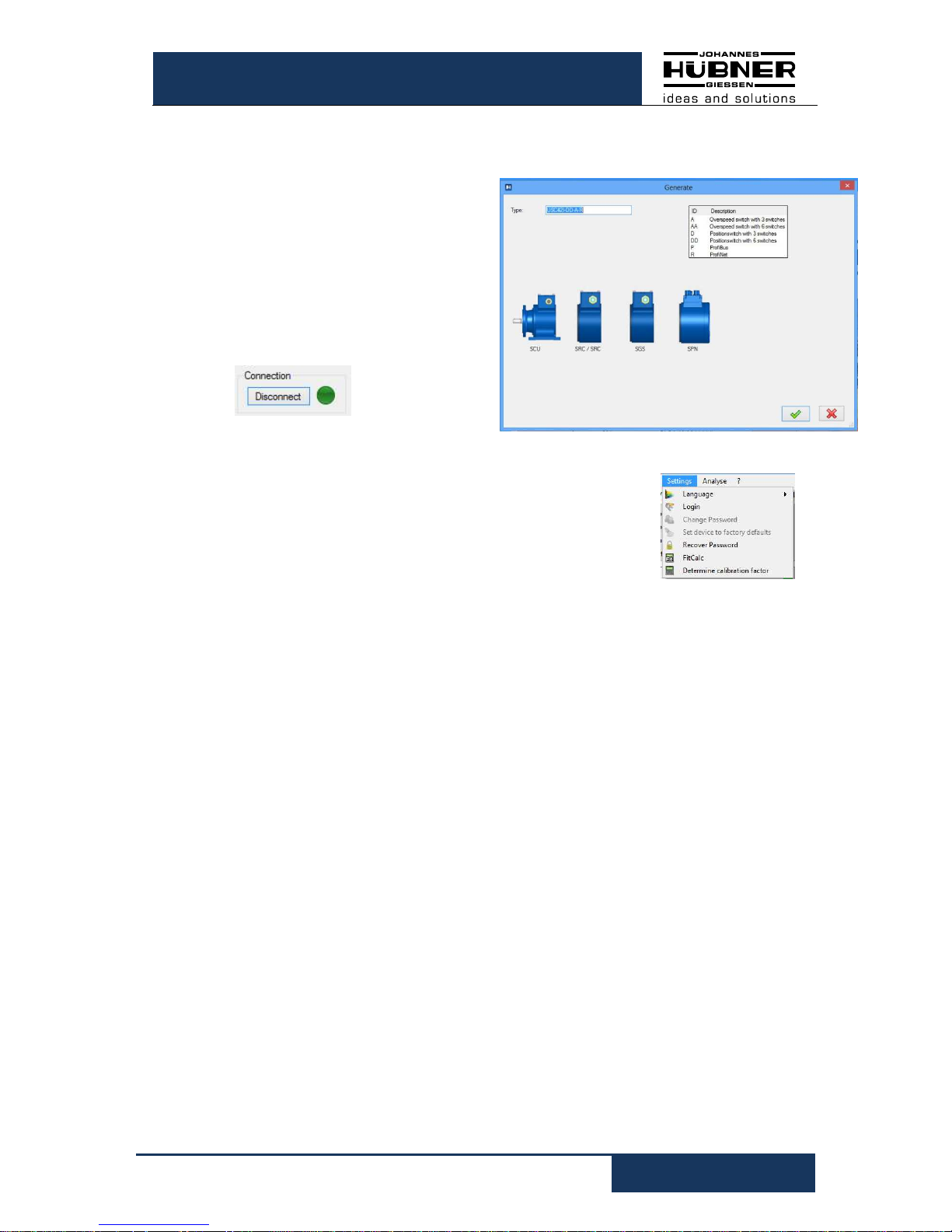
4.1.5 Pulldown menu: File Offline
In offline mode, a device parameter set can be created without USC 42as follows:
• A virtual USC 42 is created by entering
the type designation.
• The configuration of the virtual USC 42
can be carried out.
• With „Export parameters“ the
parameters are stored and can be
loaded by a USC 42 with the same type
designation.
The offline-state will be exited via
4.1.6 Pulldown menu: Options Language
Depending on the regional setting of your Windows operating
system the software language is determined. The language
'English' is selected if no corresponding data record is available. It
is possible to select a different language via the menu item
'Language'.
4.1.7 Pulldown menu: Options Login
To access and work on the assigned user level, the user must log into USC 42 via the
menu item 'Login password' with his or her password.
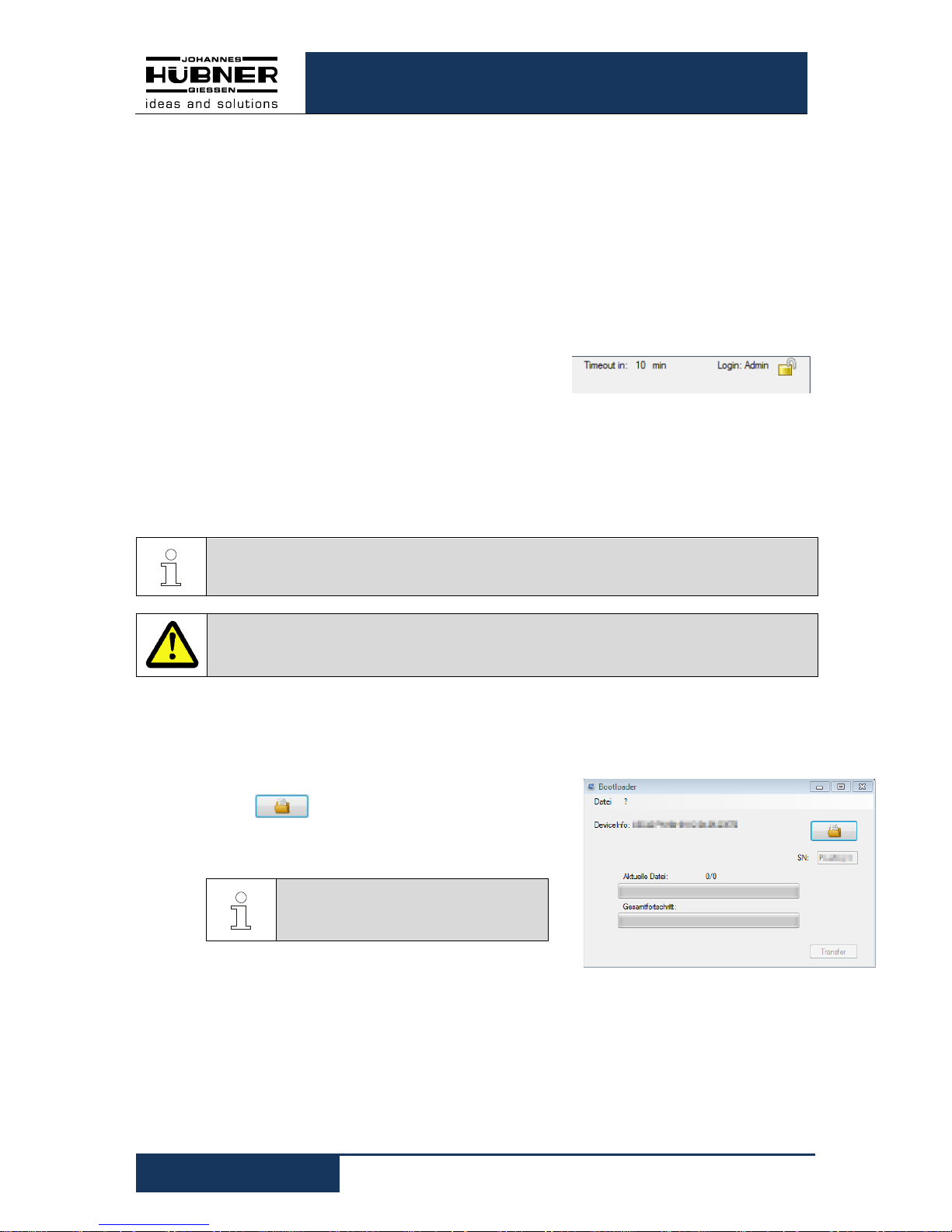
4.1.8 Pulldown menu: Options Change password
Admin and Tester passwords are assigned via the menu item 'Change password'. A
closed padlock in the header indicates that a user-specific password has been assigned.
Authorization levels:
Three authorization levels are available to the user; however, it is only possible to
activate two of these levels by means of password authentication. The password must
be between 6-12 ASCII characters (0x20 - 0x7E) in length.
Level 0: Observer (no password required)
The following functions are available on this level:
- Establish communications with USC 42
- Enter password
- Display assigned parameters
- Display saved parameter sets
Fig.
4-3
: Offline
Fig. 4-4: Settings
U-ONE®-SAFETY Compact
Configuration manual SCU C / SRC C / SGS C
12
USC42_SCU-KonfigManual-en_R5
Level 1: Tester (password level 1)
On this level the following functions are available in
addition to those on level 0:
- Perform test of switch
- Generate test logs
Level 2: Admin (password level 2)
On this level the following functions are available in
addition to those on level 1:
- Change parameters
- Save parameter sets
Default passwords on delivery are 'huebner1' for
password level 1 and 'huebner2' for password level 2.
A padlock with an open shackle symbolizes that the
password “huebner2” has not yet been changed;
consequently, the configuration is not secured against unauthorized changes.
A closed padlock shackle indicates the configuration is securely protected against
unauthorized changes. How to save the configuration is described in chapter 5.4.
The authorization level is displayed in plain text to the left of the padlock symbol
(here the level is: Admin), with which the user is logged into the USC 42.
PLEASE NOTE!
The login password is set ex-works to 'huebner1' or 'huebner2'.
ATTENTION!
Change the Admin password as soon as possible to protect the configuration from
unauthorized access! (See chapter 4.1.8).
4.1.9 Pulldown menu: Options firmware update
The USC 42 is prepared for a firmware update by electrically connecting terminal 1 (+ U)
and terminal 2 (Error1) during power up. After switching on, this connection must be
removed again.
The button.………..selects the update file.
„Transfer“ starts the update process.
After the update process, the device must be restarted.
NOTE!
Before the restard, the connection
must be removed.
Fig. 4-5: Partial view header
Fig. 4-6: firmware update

U-ONE®-SAFETY Compact
Configuration manual SCU C / SRC C / SGS C
USC42_SCU-KonfigManual-en_R5
13
4.1.10 Pulldown menu: Options Reset to factory settings
All parameters and the USC 42 will be deleted and reset to factory settings.
Factory settings:
Password level1
Password level2
huebner1
huebner2
Operating mode
Position and
speed mode
Reset and preset
inputs
Deactivated
Speed and position
switching points
Deleted
Error reset with
software only
Active
Test pulse duration
1 ms
T/ti 1000
Current output
Deactivated
Current output
source
Position
dependent
Error reset with
software only
Active
Incremental output
(optional)
4096
pulses per
revolution
4.1.11 Pulldown menu: Options Recover password
If a user forgets his/her password, it is possible to
assign a new password using the “Recover Password” function and following the steps below:
• Select “Recover Password”.
• To generate a recovery key click the
button, then click the
button to send the request to the manufacturer immediately or later if there is no Internet connection.
• A recovery password will be generated
and sent back to the designated recipient.
• It is possible to assign a new password
once the recovery password has been entered in the appropriate field.
Fig. 4-7: recover password
U-ONE®-SAFETY Compact
Configuration manual SCU C / SRC C / SGS C
14
USC42_SCU-KonfigManual-en_R5
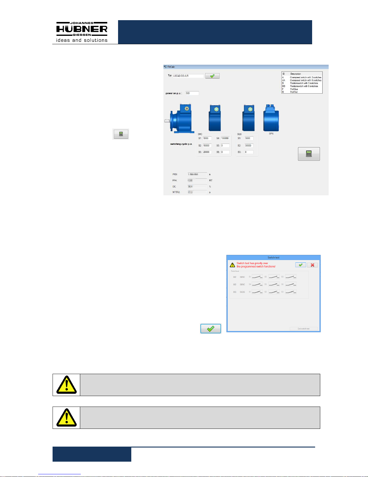
4.1.12 Pulldown menu: Options FitCalc
The characteristic safety values
of the device depend on the
number of relay switching cycles. The type determines the
number of relays.
Switching cycles p.a.: Number
of relay switching cycles per annum.
Click the button to calculate the characteristic safety values for a service life of
20 years
.
4.1.13 Pulldown menu: Options Determine calibration factor
see chapter 5.3.2
4.1.14 Pulldown menu: “Analysis” switch test
It is possible to alter the switch status by means of
a switch test incorporated in the configuration
software US42Pro. The switch test is only available
when the encoder shaft is at a standstill.
It is possible to oversee the changes to the
statuses of the switches via the Switch test dialog
box.
To confirm and activate the switch test click
CAUTION!
An error will be triggered if the encoder shaft turns during the switch test.
CAUTION!
The switch test has priority over programmed switching functions.
Fig. 4-9: Switchtest
Fig. 4-8: FitCalc

U-ONE®-SAFETY Compact
Configuration manual SCU C / SRC C / SGS C
USC42_SCU-KonfigManual-en_R5
15
4.1.15 Pulldown menu „?“
• Info
Displays the software version and Johannes Hubner contact details.
• Help
Opens the current configuration data in PDF format.
• Documentation
Opens the folder containing the USC 42 documentation. This is where the connection
diagrams, dimension drawings and operating and assembly instructions and the
configuration manual are stored.
4.1.16 Generate support file
In the pull-down menu "?" Under "Info" with the
button a support file is
generated, which serves for the error analysis.
If the e-mail checkbox is activated, the file is
transferred directly to the installed e-mail program.
4.1.17 Display calibration settings
The calibration settings are displayed here and also changed with „Start parameterization“.
4.1.18 Display device data
All device data, grouped according to the terminal boxes, are displayed here.
NOTE!
Please send the support file with a
short description of the conditions under which the error occurred, by email
to the manufacturer.
Fig. 4-10: Info
Fig. 4-11: Device data

U-ONE®-SAFETY Compact
Configuration manual SCU C / SRC C / SGS C
16
USC42_SCU-KonfigManual-en_R5
4.1.19 Fault memory
#: Memory
Time: Time of error occurrence
(Operating hours)
The error memory is a ring memory and can accommodate 100 error entries. Internal errors should be sent to the manufacturer for analysis.
The button in the display area of the fault memory generates an error log file,
which can then be saved.
4.2 User interface - display section
The display section (left column):
• Displays the device type
• Displays present position, speed and current values.
• Lists all modules of the USC 42.
The assignment to the individual terminal boxes is displayed as X1, X2, X3 in the
same sequence that mirrors how the modules are arranged (see
Fig. 5-3
).
X1 is always the terminal box of the SCU C.

U-ONE®-SAFETY Compact
Configuration manual SCU C / SRC C / SGS C
USC42_SCU-KonfigManual-en_R5
17
5 Configuring USC 42
You must first calibrate the position system before configuring USC 42
(chapter 5.3). Device calibration and device configuration operations are only possible
on the password level “Admin”.
CAUTION!
It is only possible to assign parameters and calibrate the device when the
device is at a standstill!
The USC 42 enters a safe state if rotary motion is detected when parameters are
being assigned
5.1 Launching the software US42Pro
When the software is launched, the start
screen is displayed.
Click 'Connect' to establish communications with the USC 42 . The connection
status is indicated on the right of the button.
Display Status
grey not con-
nected
change
light green / dark
green
connected
After the connection setup, the device data are
read out. To calibrate and configure the
USC 42 the user must first log in using the
Admin password.
ATTENTION!
Change the Admin password 'huebner2' to protect the configuration from unauthorized access (chapter 4.1.6).
5.2 Operating mode
5.2.1 Speed mode
Select the operating mode “Speed mode” if no position dependent switching points or
position dependent current values 4 mA…20 mA are used.
It is not necessary to calibrate the USC 42 in this operating mode.
5.2.2 Position and speed mode
Select the operating mode “Position and speed mode” if position dependent switching
points or position dependent current values 4 mA…20 mA are used.
In this operating mode it is necessary to calibrate the USC 42 (see Chap.5.3).
Fig. 5-1: Start screen
Fig. 5-2: Login

U-ONE®-SAFETY Compact
Configuration manual SCU C / SRC C / SGS C
18
USC42_SCU-KonfigManual-en_R5
5.3 Calibrating the position system
To calibrate the position system (adapt the internal device processing to mirror actual
conditions at the place of installation) it is necessary to determine the system limits, calibration point, calibration factor and unit.
• The system limits define the max. possible working range. An error will be
triggered if values exceed or fall below the defined range.
PLEASE NOTE!
To avoid system limit errors ensure sufficient clearance between the system limits and the switching points.
• The operating range must not exceed 32768 rotations of the device shaft.
• The preset position value is a defined position point (calibration point).
• The calibration factor is the adaption factor between system units and device units.
It is assumed that this ratio is constant.
If unknown, it is possible to determine the calibration factor via the menu item
“Options Determine calibration factor” (see Chap.5.3.2).
In this instance it is possible to determine the calibration factor with the aid of 2
calibration points, the interval between which should be as great as possible but must
not exceed the system limits.
Fig. 5-3: Calibrating the system

U-ONE®-SAFETY Compact
Configuration manual SCU C / SRC C / SGS C
USC42_SCU-KonfigManual-en_R5
19
5.3.1 Calibration
1. Select the desired unit via the pulldown menu
2. Enter the values for the system limits and the calibration point (preset).
The following constraint applies:
Lower system limit < calibration point < upper system limit
3. Enter calibration factor. For information on calculating the calibration factor see Chap.
5.3.3.
4. To save values to the USC 42 click , see Chap. 5.4.
5. Move to the calibration point (preset), shut down the drive and click the button.
Thecurrent position is saved as the calibration point.
6. To complete the calibration procedure click button. The USC 42 is
calibrated and can now be configured.
5.3.2 Determining the calibration factor with two calibration points
1. Enter calibration point 1 and calibration point 2.
The following constraints apply:
• Lower system limit < calibration point 1
• Calibration point 1 < calibration point 2
• Calibration point 2 < upper system limit
2. Move to calibration point 1 and shut down the drive,
click the button . The current position is saved as calibration point 1.
3. Move to calibration point 2 and shut down the drive, click the button . The
current position is saved as calibration point 2.
4. The calibration factor has been calculated, saved to the clipboard and can now be inserted in the appropriate dialog box.
5.3.3 Determining the calibration factor by calculation
Calibration factor = (device shaft rotations) x 8192 / Actual path in number of plant units
Example:
34.5 m travel corresponds to 125.7 rotations of the device shaft.
Calibration factor = 125.7 x 8192 / 34.5 = 29847.37
Fig. 5-4:
Determining the
calibration
factor

U-ONE®-SAFETY Compact
Configuration manual SCU C / SRC C / SGS C
20
USC42_SCU-KonfigManual-en_R5
5.4 Saving configuration- or parameterisation data in the USC 42
All entries are formally checked prior to data transmission.
Incorrect entries are highlighted red and data transmission to the USC 42 are prevented.
If the entries comply with the conditions
above (chapter 5.3.2), the values are
transmitted to the USC 42, checked, activated and saved temporarily.
The compare dialog box displays the
values entered in the input mask and the
values read out of the USC 42 (Fig. 5-5).
The user confirms the values are correct
by clicking the green tick.
The values are only now permanently
stored.
Fig. 5-5:
Comparison dialog box

U-ONE®-SAFETY Compact
Configuration manual SCU C / SRC C / SGS C
USC42_SCU-KonfigManual-en_R5
21
6 Functions
6.1 SCU C module
The SCU C module (Safety-Control Unit) is the central control unit of the USC 42.
To assign the module a user-defined designation click the symbol . That makes it easy
to allocate the device on site (for example, “drive 2"). The length of the designation is
limited to 12 characters.
On the tabbed page “Options” it is possible to make the following settings.
6.1.1 Digital inputs
The inputs must be activated prior to use. Both inputs are 2-channel types (Cat. 3) and
active low; in other words, when quiescent the inputs must be high. A falling edge at
both channels initiates the process. Valid rising edges initiate the process. The duration
of the low level signal T1 can be configured - and is the same for both inputs.
• Reset:
A reset procedure re-initializes the whole
USC 42 system; it also resets errors in
line with parameter assignments.
• Preset:
A preset procedure sets the current
position to the preset position configured
in the device. A low level signal at the
status output (approx. 1s) acknowledges
a valid preset procedure.
The time T1 can be set between 20
ms … 200 ms or 200 ms … 2000 ms
(factory setting: 200 ms … 2000 ms).
To alter the behaviour of the Reset and Preset
inputs from Low active to High active select the
“Preset/Reset 1 active” check box.
PLEASE NOTE!
If test pulses (Fig. 6-3) are used on the inputs they must not exceed max. ¼
of the min. duration of T1 (5ms or rather 50 ms).
CAUTION!
It is only allowed to set a preset “on the fly” if a risk analysis determines the
application is suitable to allow this function.
CAUTION!
A preset does not influence the position value of the bus module (SPB,
SPN). It is only possible to alter this position value via the bus interface.
Fig. 6-1
Preset inputs
Fig. 6-2
Digital inputs

U-ONE®-SAFETY Compact
Configuration manual SCU C / SRC C / SGS C
22
USC42_SCU-KonfigManual-en_R5
6.1.2 Digital outputs
There are 2 digital outputs: Status and error output.
Both outputs are 2 channel (Cat. 3) types. Both channels
of an error output must have the same status
(open/closed) and both must be monitored by the application. An error will be flagged if the channels are not the
same.
• Error output:
When the status is error-free both channels of the error output are high and transmit
test pulses (factory setting see Fig. 6-3). The USC 42 monitors the output to ensure it
is functioning properly.
CAUTION!
If the error output is utilized to detect a device error it must be subject
to a safety-related evaluation (see document “USC 42_Manual-en_R..”
Chapter: Application examples).
The receiver must suppress the test pulses to avoid unwanted switching operations.
- The following settings are available to set the duration of the test pulses:
100 ms, 10 ms, 1 ms, off (factory setting: 1 ms).
- For the quotient ‘test pulse interval / test pulse duration’ (T/ti) it is possible to select
10, 100, 1000 (factory setting: 1000).
- The test pulse offset (test pulse offset between channels) tc = 2* ti cannot be set.
For non-safety relevant applications it is possible to deactivate the test pulses. An
error is indicated by a low-level signal at the error output, which can only be reset via
the configuration software "US42Pro" (factory setting). It is possible to set the error
performance via the software so that an error will also be reset by interrupting the
supply voltage (> 2s) or by initiating a reset at the reset input).
The reset always initiates a system reboot including a complete system test. If an
error is determined again, the device remains in an error condition. Error logs are
saved in the error memory.
CAUTION!
The "fault reset via the reset input or power supply interruption" option
may be used only if a risk analysis has shown that the application is
suitable.
• Status output:
The status output indicates the operating status in conjunction with the error output of
the USC 42 (see separate operating and assembly instructions. Chapter: Operating
conditions and indicators). The status output does not issue any test pulses.
Fig. 6-3: Error output

U-ONE®-SAFETY Compact
Configuration manual SCU C / SRC C / SGS C
USC42_SCU-KonfigManual-en_R5
23
6.1.3 Current output (non safety related)
The current output can be set to speed or position dependent on the menu and must be
activated before use.
6.1.3.1 Configuring the position-dependent current output
To configure the position-dependent current output it is necessary to enter 2 position values, which must be within the
system limits.
The smaller position value is assigned current I
min
= 4 mA and
the larger position value I
max
= 20 mA.
The following restriction applies:
• Pos1 < Pos2
If the current position is outside of the defined position range,
the current output is switched to high impedance (I = 0 mA).
(Factory setting).
Alternatively, it is possible to select a setting to take effect in
the event the value falls below or exceeds the determined position range 4 mA or 20 mA.
6.1.3.2 Configuring the speed-dependent current output
To configure the speed-dependent current output it is necessary to enter the speed
n20 mA
. When at a standstill a current of
4 mA flows.
The following constraint applies:
• n
20 mA
< (approved mechanical speed -10%)
If the speed exceeds the speed range (n
current
> n
20 mA
), the current output is switched to high resistance
(I = 0 mA) – (factory setting).
Alternatively, it is possible to select a setting to take effect in
the event the value exceeds the determined position range
20 mA
.
6.1.4 Configuring the incremental output (non safety-related)
The incremental output is optional. To configure the incremental output it is possible to select a pulse rate of 1024 or
4096
(factory setting: 4096).
Fig. 6-4:
Configuring
position depend-
ent-current output
Fig. 6-6 Configuring incremental output
Fig. 6-5:
Configuring speed dependent
-
current output

U-ONE®-SAFETY Compact
Configuration manual SCU C / SRC C / SGS C
24
USC42_SCU-KonfigManual-en_R5
6.2 SRC C module
The SRC C module is a position switch module and contains 3 or 6 position switches.
The position switch opens or closes depending on the position value. The position
switches are 2 channel types (2 NO contacts, Cat. 3).It is possible to implement a cam
with a single switch; in other words, a switch-on and switch-off position and the associated hysteresis switching points.
The position values to be entered must be within system limits. It is possible to assign
each position switch an application-specific designation (max. 12 characters). Switching
modules with 6 position switches are configured on 2 monitor display screens. The parameters are entered in the table as shown opposite.
The values are highlighted yellow if there is a risk that
the minimum changeover interval (2 ms) between 2
switching conditions could be undershot. If such an
event occurs the user must check the time interval in
his application.
• P1: Hysteresis switching point of P2.
• P3: Hysteresis switching point of P4.
The following condition applies:
P1 < P2 < P3 < P4
• Inverted: The switch operates inverted (see switch
S3).
• Error switch: Switch opens only in the event an
error occurs (see switch S2).
• Open if an error occurs:
Switch operates as configured, but opens if an error
occurs.
The switching points are depicted in their correct
position in the graphic opposite.
A marker indicates the current position.
Click "Write to device" to finish configuring the module
Fig. 6-7: Warning notice
Fig.: 6-8 Configuration SRC C module
U-ONE®-SAFETY Compact
Configuration manual SCU C / SRC C / SGS C
USC42_SCU-KonfigManual-en_R5
25
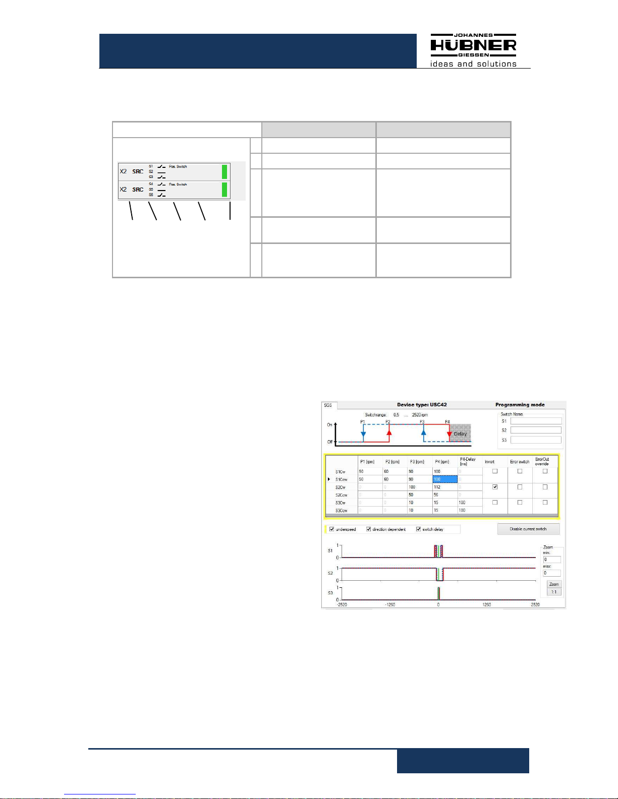
6.2.1 Depiction in the display section
The module is depicted as follows in the display section:
The switching states of the individual switches are represented by switch symbols .
Description Meaning
1 2 3 4 5
1 Module position
X2: 2. Terminal box
2 Module type
SRC: Position switch module
3 Switch statuses
Graphic switch symbol
Black: Error-free
Gray: Not configured
Red: Error
4 User designation
Switch designation assigned
by user
5 Module status
Gray: Not configured
Green: error-free
Red: Error
6.3 SGS C module
The SGS C-module is a speed switch module. The speed switch opens or closes depending on the speed. A speed switch module has 3 or 6 speed switches. Switching
modules with 6 speed switches are configured on 2 configuration screens. Fundamentally, all switching speed inputs must be within the device-specific switching range
0.5-2520 rpm.
The speed-dependent functions are depicted in a graphic in the top part of the
screen.
The input fields for entering speed switching points are displayed in the lower part of
the screen in table form. One line is allocated to each respective switch (S1-S3 or
S1R to S3L).
The columns are assigned to the respective speed switching points P1 to P4, and
the switching delay P4 (max. 300 ms).
The following condition applies:
P1 < 0.9 x P2 < 0.9 x P3 < 0.9 x P4
or P1 = P2 = 0
The switching points are depicted in the graphic opposite. A marker indicates the
current speed
Fig. 6-10: Configuration SGS C module
Fig.: 6-9 Display Area
U-ONE®-SAFETY Compact
Configuration manual SCU C / SRC C / SGS C
26
USC42_SCU-KonfigManual-en_R5
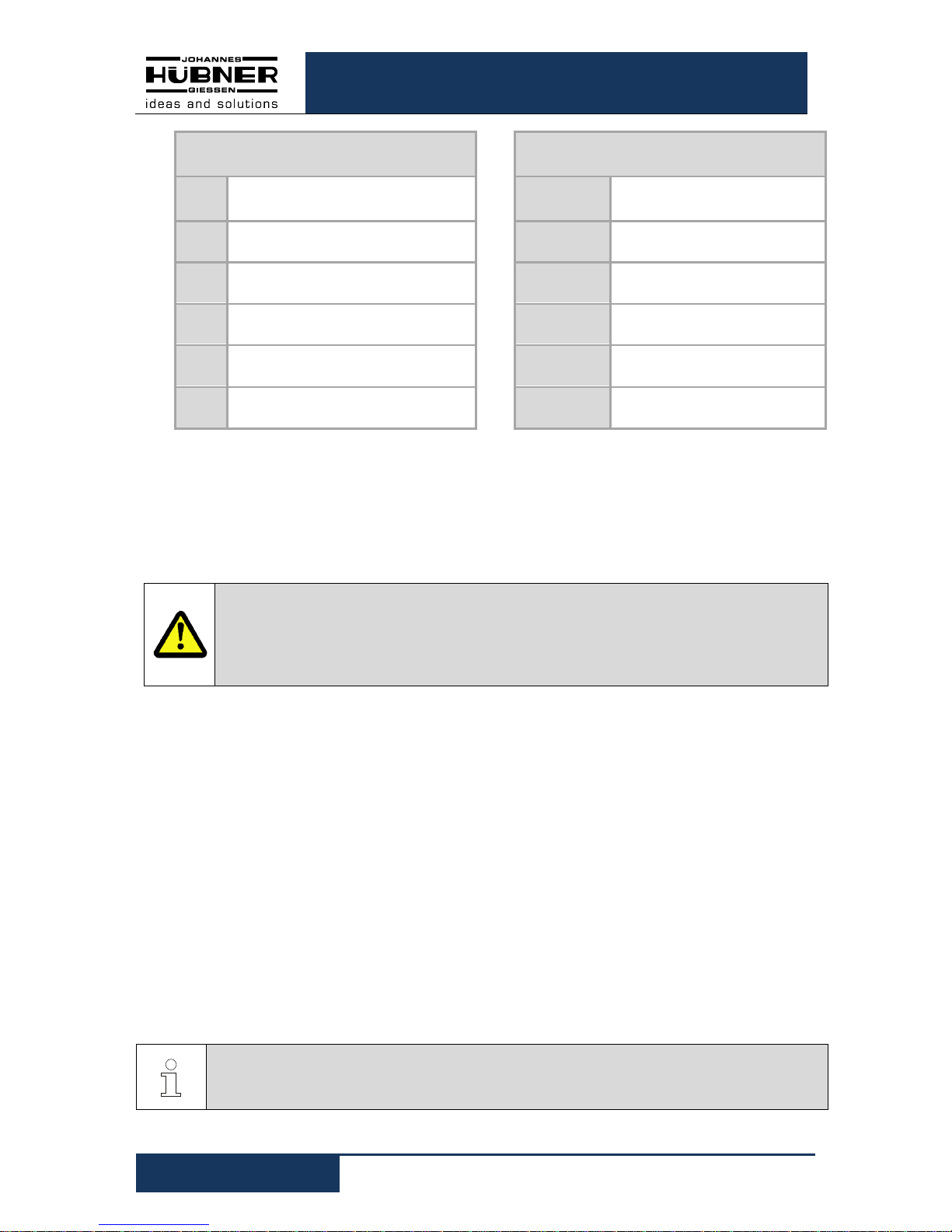
The switches listed in the lines are allocated
as follows
The values listed in the columns are allocated
as follows
S1R
Switching speeds of switch 1 for
clockwise direction of rotation
P1
Hysteresis switching speed for
underspeed detection
S1L
Switching speeds of switch 1 for anticlockwise direction of rotation
P2
Cut-in speed for underspeed
detection
S2R
Switching speeds of switch 2 for
clockwise direction of rotation
P3
Hysteresis switching speed for
overspeed detection
S2L
Switching speeds of switch 2 for anticlockwise direction of rotation
P4
Cut-off speed for overspeed
detection
S3R
Switching speeds of switch 3 for
clockwise direction of rotation
P4 - Delay
Delay time before cut-off of the
switching point P4 [ms]
S3L
Switching speeds of switch 3 for anticlockwise direction of rotation
Only those lines and columns are displayed that are relevant to the respective function
selected by checking the appropriate boxes.
An input value "0" in the fields P1 … P4 deactivates the corresponding switch.
An input value "0" in the fields P1 … P2 deactivates underspeed detection
(see Chapters: 6.3.1, 6.3.2).
CAUTION!
When switching delay is activated the actual cut-off speed can be higher than the
set cut-off speed!
Observe also the information on determining switching accuracy described in the
Operating and Assembly Instructions " USC 42_Manual"!
The module is depicted in the display section as in
Fig. 6-10
Click "Write to device" to finish configuring the module.
6.3.1 Underspeed
Underspeed is detected. The respective switch closes first when speed P2 is exceeded;
the switch is opened again when the speed falls below the P1 threshold. The input columns for "P1" and "P2" are depicted if underspeed detection is activated.
6.3.2 Rotation direction dependent
The switching speeds S1R … S3R apply to clockwise direction of rotation. The speeds
S1L … S3L apply to anticlockwise direction of rotation.
The input lines for S1R-S3R as well as S1L-S3L are depicted if 'rotation direction dependent switching' is activated.
If no 'rotation direction dependent switching' is activated the switches S1 ... S3 are not
labelled with a direction of rotation indicator R or L; the entered switching speeds apply
independent of the direction of rotation.
PLEASE NOTE!
If 'rotation direction dependent switching and underspeed are selected, the underspeed function must be equal for both directions of rotation. Either active or inactive.

U-ONE®-SAFETY Compact
Configuration manual SCU C / SRC C / SGS C
USC42_SCU-KonfigManual-en_R5
27
6.3.3 Switching delay
The adjustable switching delay makes it possible to prevent the overspeed switch
switching if the limit speed is exceeded only briefly. That can be appropriate during load
shedding, for example. If the speed P4 is exceeded the switches S1, S2 and S3 close,
and open only after the delay time set in the "Delay" field has elapsed. It is possible to
set the time between 0 and 300 ms. The cut-off function is not triggered if the speed
again falls below the P4 figure within the set delay time.
PLEASE NOTE!
The delay time applies only to the cut-off function when the speed P4 is exceeded.
All other switching operations are triggered immediately.
6.3.4 Display in the display area
In the display area, the module is depicted as shown in Fig.
6-11.
6.4 Input accuracy of switching points
SGS C-Modul:
Switching speed n
Input accuracy
X: Integer places
Y: Decimal places
n < 100 rpm XX.YY (e.g.: 15.87)
100 >= n < 1000 rpm XXX.Y (e.g.: 280.3)
n >= 1000 rpm XXXX (e.g.: 2050)
SRC C-Modul:
The input accuracy of the position switching points depends on the calibration factor.
The input of position switching points is limited to 9 decimal places. The number of
places after the decimal point is limited to 3 decimal places.
Calibration factor k
Input accuracy position
switching points
X: Integer places
Y: Decimal places
k < 10
XXXXXXXX
e.g.: 27354
10 >= k < 100
XXXXXXX.Y
e.g.: 27354.3
100 >= k < 1000
XXXXXX.YY
e.g.: 27354.34
k >= 1000
XXXXX.YYY
e.g.: 27354.345

U-ONE®-SAFETY Compact
Configuration manual SCU C / SRC C / SGS C
28
USC42_SCU-KonfigManual-en_R5
6.5 Error handling
Numerous diagnostic measures check the functions and operating conditions of the
USC 42 at power up and during runtime.
In the event of a deviation, the error state (safe
state) is initiated and the error is stored in the error
memory.
An error distinction is made between "internal errors" and "external errors".
External errors are caused by external influences, e.g. exceeding the max.
permissible speed or exceeding the max. permissible temperature. The errors are
explained in the parameterization software with a brief description of the error, as
described in Chap. 6.5.1 displayed.
External errors are reset by a reset (reset input or reset button in the US42Pro
software) or by interrupting the supply voltage (> 2s).
Internal errors are e.g. triggered by deviations of the device-internal program
sequence. The errors are displayed in the parameterization software with error
number and the designation "internal error". An analysis of the cause of the error is
only possible with expert knowledge. To do this, the user must send the contents of
the fault memory to the manufacturer (see chapter 4.1.19).
Internal errors can only be reset via the reset
button in the US42OPro software (factory
setting).
Resetting the internal error can be set with the US42Pro software to match that of
the external error.
Resetting the error triggers a system restart with a complete system check. If an
error is detected again, the USC 42 remains in fault state.
The error state can be assigned to a switching output with the parameterization
software.
Fig. 6-12
: Error message
Fig. 6-13: Reset internal error

U-ONE®-SAFETY Compact
Configuration manual SCU C / SRC C / SGS C
USC42_SCU-KonfigManual-en_R5
29
6.5.1 Error table
Error no. Description
30 Undervoltage detected
31, 32 Overvoltage detected
35 Fell below min. temperature
36 Max. temperature exceeded
40 Error reset input
45 Error preset input
48 Error output
50 Fall below system limit
51 System limit exceeded
52 Operating range (system limit) too great
55 Maximum device speed exceeded
60 Start-up during parameterization
61 Start-up during switch test
62 Start-up during preset (software only)
63 Invalid condition for preset
65 Timeout during parameterization
66 Switched off during parameterization
67 Switched off while saving parameters
68 Start-up during factory reset
100-255 Internal diagnostics error detected
 Loading...