

Hubner EGS 41, EGS H 41 Operating And Assembly Instructions Manual
English
Construction type B35
Hollow shaft design
Operating and Assembly Instructions
ELECTRONIC OVERSPEED SWITCH
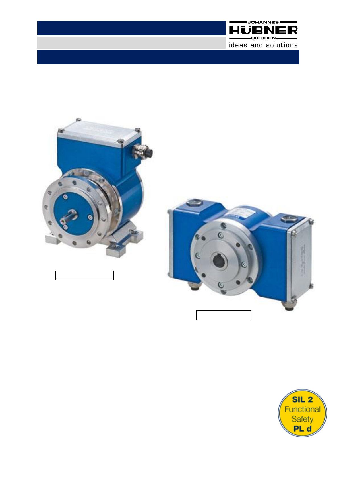
EGS® 41 in construction type B5 (flange), B35 (flange and foot)
EGS®H 41 (hollow shaft design)
certificated according EN 61508 SIL2 and DIN EN ISO 13849-1 PL d
Read the Operating and Assembly Instructions prior to
assembly, starting installation and handling!
Keep for future reference
Translation of the original Operating and Assembly Instructions Published January 2017

Electronic Overspeed Switch EGS(H) 41
2
EGS(H)41_Manual_En.doc Build: 20209
Trademark
EGS® is a registered trademark of Johannes Hubner Fabrik elektrischer Maschinen GmbH.
Windows® is a registered trademark of Microsoft Corporation in the Unites States and other countries.
Viton® is a registered trademark by Du Pont.
Loctite® is a registered trademark.
All other brand names and product names are trademarks or registered trademarks of their respective
owner.
Protected trademarks bearing a ™ or
However, the statutory rights of the respective owners remain unaffected.
Manufacturer / publisher
Johannes Hubner
Fabrik elektrischer Maschinen GmbH
Siemensstraße 7
35394 Giessen
Germany
Phone: +49 641 7969 0
Fax: +49 641 73645
E-Mail: info@huebner-giessen.com
www.huebner-giessen.com
Headquarters: Giessen
Court of registration: Giessen
Commercial register number: HRB 126
The manual has been drawn up with the utmost care and attention. Nevertheless, we cannot exclude
the possibility of errors in form and content. It is strictly forbidden to reproduce this publication or parts
of this publication in any form or by any means without the prior written permission of
Johannes Hubner Fabrik elektrischer Maschinen GmbH.
Subject to errors and changes due to technical improvements.
Copyright © Johannes Hubner Fabrik elektrischer Maschinen GmbH
All rights reserved.
®
symbol are not always depicted as such in the manual.

Electronic Overspeed Switch EGS(H) 41
3
Directory
1 General .......................................................................................................................... 5
1.1 Information about the Operating and Assembly Instructions ................................................... 5
1.2 Scope of delivery ...................................................................................................................... 5
1.3 Explanation of symbols ............................................................................................................ 5
1.4 Disclaimer................................................................................................................................. 6
1.5 Copyright .................................................................................................................................. 6
1.6 Guarantee terms ...................................................................................................................... 6
1.7 Customer service ..................................................................................................................... 6
2 Safety ............................................................................................................................ 6
2.1 Responsibility of the owner ...................................................................................................... 6
2.2 Personnel ................................................................................................................................. 6
2.3 Personal protective equipment ................................................................................................ 7
2.4 Special dangers ....................................................................................................................... 7
2.4.1 Electrical current ............................................................................................................. 7
2.4.2 Rotating shafts / Hot surfaces ......................................................................................... 7
2.4.3 Safeguarding against restart ........................................................................................... 7
3 Technical Data ................................................................ .............................................. 8
3.1 Type plates ............................................................................................................................... 8
3.2 Type key ................................................................................................................................... 9
3.3 Electrical and mechanical data .............................................................................................. 10
3.3.1 Connected loads, environment ..................................................................................... 10
3.3.2 Electrical Outputs .......................................................................................................... 10
3.3.3 Mechanical Data ............................................................................................................ 11
3.3.4 Degree of protection ..................................................................................................... 11
4 Installation and commissioning .................................................................................12
4.1 Safety instructions .................................................................................................................. 12
4.2 Technical information ............................................................................................................. 12
4.3 Required tools ........................................................................................................................ 13
4.4 Mounting preparations ........................................................................................................... 13
4.5 Mounting B5 type (flange) ...................................................................................................... 13
4.6 Mounting B35 type (flange and foot) ...................................................................................... 15
4.7 Mounting tolerances for Construction Type B5 and B35 ....................................................... 16
4.8 Attaching additional devices................................................................................................... 17
4.9 Mounting hollow-shaft type overspeed switches ................................................................... 19
4.10 Dismantling............................................................................................................................. 21
4.10.1 Safety instruction .......................................................................................................... 21
4.10.2 Dismantling the encoder type B5 and B35 .................................................................... 21
4.10.3 Dismantling hollow shaft type overspeed switches ...................................................... 21
4.11 Electrical connection and start up .......................................................................................... 22
4.11.1 Preparing cables ............................................................................................................ 22
4.11.2 Electrical connection ..................................................................................................... 22
5 Structure and function ................................................................................................24

Electronic Overspeed Switch EGS(H) 41
4
5.1 Brief description ..................................................................................................................... 24
6 Functional safety .........................................................................................................25
6.1 Device data ............................................................................................................................ 25
6.1.1 Characteristic safety values ........................................................................................... 25
6.1.2 Timing ............................................................................................................................ 26
6.1.3 Switching accuracy ........................................................................................................ 26
6.1.4 Safe state ....................................................................................................................... 26
6.1.5 Service life of the bearings ............................................................................................ 27
6.2 Intended use .......................................................................................................................... 28
6.3 Improper use .......................................................................................................................... 28
6.4 Inspections ............................................................................................................................. 28
6.4.1 Safety instructions personnel ........................................................................................ 28
6.4.2 Maintenance information ............................................................................................. 28
6.4.3 Inspection schedule ....................................................................................................... 29
6.5 Fault table............................................................................................................................... 29
6.6 Error table............................................................................................................................... 30
7 Replacement parts ......................................................................................................31
8 Transport, packaging and storage .............................................................................32
8.1 Safety information concerning transport ................................................................................ 32
8.2 Goods inward inspection ........................................................................................................ 32
8.3 Packaging (disposal) .............................................................................................................. 32
8.4 Storing packages (devices) .................................................................................................... 32
8.5 Returning devices (repairs/goodwill/warranty) ....................................................................... 33
8.6 Disposal.................................................................................................................................. 33
9 Dimension drawings ...................................................................................................34
9.1 EGS 41 dimension drawings .................................................................................................. 34
9.1.1 Construction type B5 (flange) ........................................................................................ 34
9.1.2 Construction type B35 (flange and foot) ....................................................................... 35
9.1.3 Construction Type B5/B14 (flange, with 2. shaft end) .................................................. 37
9.1.4 Construction type B35/B14 (flange and foot, with 2. shaft end) .................................. 39
9.2 Assembly devices .................................................................................................................. 41
9.3 EGSH 41 – dimension drawings ............................................................................................ 43
10 Connection Diagram ...................................................................................................47
10.1 Connections ........................................................................................................................... 47
11 Declaration of Conformity/Certificate ........................................................................49

Electronic Overspeed Switch EGS(H) 41
5
WARNING!
Indicates a possibly dangerous situation that can result in death or serious injury if it is
not avoided.
CAUTION!
Indicates a possibly dangerous situation that can result in minor injury if it is not
avoided.
CAUTION!
Indicates a possibly dangerous situation that can result in material damage if it is not
avoided.
NOTES!
Indicates useful tips and recommendations as well as information for efficient and
trouble-free operation.
NOTES!
Do not use a hammer or similar tool when installing the device due to the risk of damage
occurring to the bearings or coupling!
DANGER!
Life-threatening danger due to electric shock!
Indicates a life-threatening situation due to electric shock. If the safety instructions are
not complied with there is danger of serious injury or death. The work that must be
executed should only be performed by a qualified electrician.
1 General
1.1 Information about the Operating and Assembly Instructions
These Operating and Assembly Instructions provide important instructions for working with the device.
They must be carefully read prior to starting all tasks, and the instructions contained herein must be
followed.
In addition, applicable local regulations for the prevention of industrial accidents and general safety
regulations must be complied with.
1.2 Scope of delivery
Scope of delivery includes the overspeed switch, the Operating and Assembly Instructions (with SILsafety instructions) the programming software EGS41Pro(CD-ROM), and the programming cable.
1.3 Explanation of symbols
Warnings are indicated by symbols in these Operating and Assembly Instructions. The warnings are
introduced by signal words that express the scope of the hazard.
The warnings must be strictly heeded; you must act prudently to prevent accidents, personal injury,
and property damage.

Electronic Overspeed Switch EGS(H) 41
6
NOTES!
Content information, text, drawings, graphics, and other representations are protected
by copyright and are subject to commercial property rights.
It is strictly forbidden to make copies of any kind or by any means for any purpose other
than in conjunction with using the device without the prior written agreement of the
manufacturer. Any copyright infringements will be prosecuted.
DANGER!
This section provides an overview of all the important safety aspects that ensure
protection of personnel, as well as safe and trouble-free device operation.
If these safety instructions are not complied with significant hazard can occur.
1.4 Disclaimer
All information and instructions in these Operating and Assembly Instructions have been provided
under due consideration of applicable guidelines, as well as our many years of experience.
The manufacturer assumes no liability for damages due to:
Failure to follow the instructions in the Operating and Assembly Instructions
Non-intended use
Deployment of untrained personnel
Opening of the device or conversions of the device
In all other aspects the obligations agreed in the delivery contract as well as the delivery conditions of
the manufacturer apply.
1.5 Copyright
1.6 Guarantee terms
The guarantee terms are provided in the manufacturer´s terms and conditions.
1.7 Customer service
For technical information personnel is available that can be reached per telephone, fax or email. See
manufacturer´s address on page 2.
2 Safety
2.1 Responsibility of the owner
The device is used in commercial applications. Consequently the owner of the device is subject to the
legal occupational safety obligations, and subject to the safety, accident prevention, and
environmental protection regulations that are applicable for the devices area of implementation.
2.2 Personnel
Installation and commissioning as well as disassembly routines must be carried out by skilled technical
staff only.

Electronic Overspeed Switch EGS(H) 41
7
DANGER!
Life-threatening danger due to electrical shock!
There is an imminent life-threatening hazard if live parts are touched. Damage to
insulation or to specific components can pose a life-threatening hazard.
Therefore:
Immediately switch off the device and have it repaired if there is damage to the
insulation of the power supply.
De-energize the electrical equipment and ensure that all components are connected for
all tasks on the electrical equipment.
Keep moisture away from live parts. Moisture can cause short circuits.
WARNING!
Danger of injury due to rotating shafts and hot surfaces!
Touching rotating shafts can cause serious injuries.
Therefore:
Do not reach into moving parts/shafts or handle moving parts/shafts during operation.
Close to protect from injury all access openings in flanges with the corresponding plug
screw, and provided you exposed rotating components with protective covers.
Do not open covers during operation. Prior to opening the covers ensure that all parts
have come to a standstill.
The encoder can become hot during prolonged use.
In case of contact risk of burns is existing.
DANGER!
Life-threatening danger if restarted without authorization!
When correcting faults there is danger of the power supply being switched on without
authorization.
This poses a life-threatening hazard for persons in the danger zone.
Therefore:
Prior to starting work, switch off the system and safeguard it from being switched on
again.
2.3 Personal protective equipment
Wear personal protective equipment such as safety shoes and safety clothing to minimise risks to
health and safety when carrying out work such as installation, disassembly or commissioning. Adhere
to all applicable statutory regulations as well as the rules and standards determined by the owner.
2.4 Special dangers
Residual risks that have been determined based on a risk analysis are cited below.
2.4.1 Electrical current
2.4.2 Rotating shafts / Hot surfaces
2.4.3 Safeguarding against restart
Electronic Overspeed Switch EGS(H) 41
8
Manufacturer, address
With integrated FG 40 includes
CE mark
Type, year of construction
Number of pulses
Supply voltage
Serial number (S/N)
No-load current
Commission number (C/N)
Max. speed
Outputs
Supply voltage:
Switching voltage / max. switching
current
Certification
Degree of protection
3 Technical Data
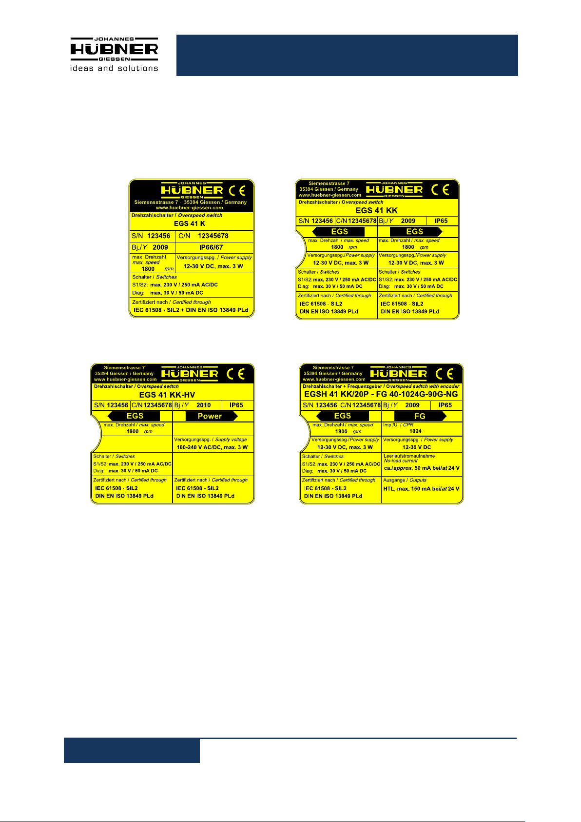
3.1 Type plates
Below are some nameplates for different device models shown.
Example EGS 41 K Example EGS 41 KK
Example EGS 41 KK – HV Example EGSH 41 KK – FG 40
The type plate is located on the side of the housing and contains the following information:
Electronic Overspeed Switch EGS(H) 41
9
3.2 Type key
Electronic Overspeed Switch
H: Hollow shaft design
HJ: EGSH with isolated bearings
Series 41
Connection Method
K: Terminal box
KK: 2 Terminal boxes
EGS (HJ) 41 K - HS - HV /20P - FG 40-1024G-90G-NG
Switching voltage
max. 30 V DC (Standard)
HS: 30 … 230 V AC/DC
Supply voltage
12 … 30 V DC (Standard)
HV: 100 … 240 V AC (in the second terminal box)
Inner diameter (hollow shaft version)
20P: Ø 20 H7 mm with keyway (standard)
16P: Ø 16 H7 mm with keyway (optional)
19P: Ø 19 H7 mm with keyway (optional)
Integrated incremental encoder
(in the second terminal box)
see Operating and Assembly Instructions FG 40
Electronic Overspeed Switch EGS(H) 41
10
Specification
Value
Supply voltage
12 … 30 VDC
Supply voltage (option HV)
100 … 240 VAC
Power consumption
max. 3 W
Programmable switching speed
(The max. switching speed = 0,9 x permissible speed
see chapter 3.3.4)
0,5 … max. 5400 rpm
Switching accuracy
(see chapter 6.1.3)
2%
Switch S1, S2
0 … 30 V DC / max. 500 mA
Max. voltage drop at the closed switch 0,7V
Switch S1, S2 (Option HS)
30 … 230 V AC/DC / max. 250 mA
Max. voltage drop at the closed switch 5V
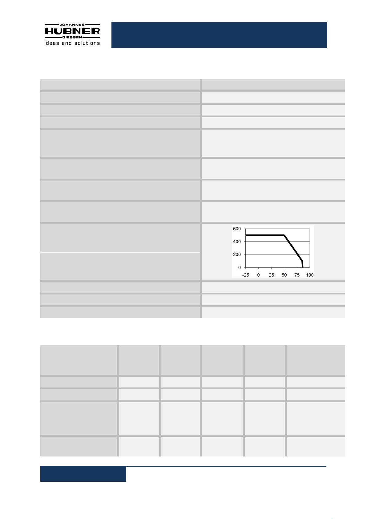
Derating:
Y-Axis: Total switch current S1 + S2 [mA]
X-Axis: Temperature [°C]
Switch diagnostic
0 … 30 V DC / max. 50 mA
Device temperature range
-25 … +85°C
Permissible relative humidity (operating)
15 … 90%
Variant
Switching
Contacts
Diagnosis-
switch
Incremental
Output
Supply
Voltage
Connection
Diagram
See chapter 10.1
EGS(H) 41K
2 1 -
12 30 VDC
PN112-400
EGS(H) 41KK
4 2 -
12 30 VDC
PN112-400
EGS(H) 41KK
– FG 40
2 1 6/8
12 30 VDC
PN112-400
+ Connection diagram for
FG40 see operating and
assembly instructions
FG40
EGS(H) 41KK - HV
2 1 -
100 .. 240
VAC
PN112-410 +
PN112-420
3.3 Electrical and mechanical data
3.3.1 Connected loads, environment
3.3.2 Electrical Outputs

Electronic Overspeed Switch EGS(H) 41
11
Description
Data
Vibration resistance
DIN EN 60068-2-6 / IEC 68-2-6 (10 … 2000 Hz)
20 g (=200 m/s²)
Shock resistance
DIN EN 60068-2-27 / IEC 68-2-27 (6 ms)
100 g (ca. 1000 m/s²)
EGS 41
Max. encoder
shaft load
Fa max. (axial) = 100 N
Fr max. (radial) = 120 N
Shaft end
11j6 x 30 mm (standard)
14j6 x 30 mm (optional)
Weight
EGS 41 K
EGS 41 KK
Approx. 3.3 kg
Approx. 3.6 kg
EGSH 41
Weight
EGSH 41 K
EGSH 41 KK
Approx .4,2 kg
Approx. 4,5 kg
Degree of protection acc. to
DIN EN 60529
Sealing
Permissible
speed
Rotor moment of
inertia
Breakaway torque
EGS 41
IP 65
standard
≤ 6000 rpm
approx. 510 gcm²
approx. 6 Ncm
IP 66
with labyrinth seal
≤ 6000 rpm
approx. 580 gcm²
approx. 6 Ncm
IP 66 / IP 67
with axial shaft
seal
≤ 4000 rpm
approx. 510 gcm²
approx. 8 Ncm
IP 66 / IP 67
with radial shaft
seal (for special
applications, e.g.
wet areas in
rolling mills)
≤ 3000 rpm
approx. 510 gcm²
approx. 9 Ncm
EGSH 41
IP 65
standard
≤ 4000 rpm
(*) ≤ 3000 rpm
approx. 1175 gcm²
approx. 10 Ncm
IP 66
with labyrinth seal
≤ 4000 rpm
(*) ≤ 3000 rpm
approx. 1325 gcm²
approx. 10 Ncm
IP 66
with axial shaft
seal
≤ 2000 rpm
approx. 1175 gcm²
approx. 25 Ncm
IP 66
with radial shaft
seal (for special
applications, e.g.
wet areas in
rolling mills)
≤ 2000 rpm
approx. 1175 gcm²
approx. 30 Ncm
NOTES!
The hollow shaft device EGSH 41 reduces the degree of protection to IP 65, if the cover
plate is not mounted. At maximum speed the permissible ambient temperature will be
reduced to 60°C.
3.3.3 Mechanical Data
3.3.4 Degree of protection
(*) with isolated bearings – hybrid bearings –

Electronic Overspeed Switch EGS(H) 41
12
NOTES!
Observe the safety instructions contained in Chapter 2 when installing or working on the
device!
NOTES!
Do not use a hammer or similar tool when installing the device due to the risk of damage
occurring to the bearings or coupling!
4 Installation and commissioning
4.1 Safety instructions
The electronic overspeed switch from the EGS(H) 41 series is a switching device designed to ensure
the safety of machines, devices and systems in line with application requirements, and contribute
towards the overall classification of a given safety category.
Inspection
Observe and adhere to all relevant regulations, guidelines and laws when utilising the EGS(H) 41 to
monitor overspeeds in safety-relevant machines and systems; your should also inspect the device on
a regular basis. Inspections must be recorded in a log book (please refer to the inspection schedule in
Chapter 6.4.3).
Furthermore, we remind you of your obligation to adhere to the various country-specific laws,
guidelines and standards. You must also observe the supplied operating and installation instructions
that in addition to regulating safety and commissioning procedures for the device, individual
components and the entire system also define regular inspection schedules (electrical and mechanical
functional testing).
Personnel
Installation and commissioning must be carried out by skilled technical staff only.
4.2 Technical information
Ambient temperature
The max. permissible ambient temperature depends on the speed and degree of protection of the
device, the signal frequency, the length of the signal cable and the place of installation (please refer to
Chapter 3.3).
Degree of protection
To fulfill degree of protection requirements the diameter of the connection cable must correspond to
that of the cable gland (please refer to Chapter 9 dimension drawings)
Deep groove ball bearings
The electronic overspeed switch EGS(H) 41 is fitted with maintenance-free, greased "for-life" deep
groove bearings. (Bearing life see chapter 6.1.5). Bearings must be changed by the manufacturer
only. Opening the encoder renders the guarantee null and void.
Screw retention
We recommend using Loctite® 243 threadlocker (medium strength) on all fastening screws to prevent
loosening.
Electronic Overspeed Switch EGS(H) 41
13
NOTES!
Fastening screws and earth cable are not included in the range of supply.
NOTES!
For a mounting example please refer to dimension drawing HM 09 M 57 263a Chapter
9.1.1
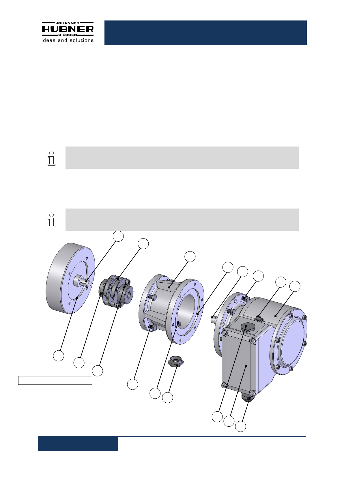
1 9 2
10
3
12
13 4 7 6 15 8 5
14
17
11
16
Fig.1: EGS 41 construction type B5
4.3 Required tools
Spanners: 10 mm, 13 mm, 22 mm, 24 mm
Allen keys: 2 mm, 3 mm, 5 mm
Flat-blade screwdrivers:
Assembly grease (acid-free)
Loctite
®
243 (medium strength threadlocker)
4.4 Mounting preparations
1. Ensure all accessories are available (please refer to Chapter 9 dimension drawings).
2. Preparing the place of attachment: Clean the (motor) shaft, centering, bolting surfaces and
fastening threads; check for damage. Repair any damage!
4.5 Mounting B5 type (flange)
)
1. Lightly grease the (motor) shaft (1) and centering (9).
2. Fit coupling (2) onto (motor) shaft.

Electronic Overspeed Switch EGS(H) 41
14
NOTES!
You must be able to mount the coupling without force. Ream out the bores of used
couplings, if necessary! We recommend our zero-backlash, torsion-resistant HK 5
coupling to attach the overspeed switch. Please refer to the catalougue Torsion
Resistant Couplings for overspeed switch.
NOTES!
If possible, fit the intermediate flange in a manner that ensures the screwed sealing plug
(14) points downwards!
NOTES!
You must be able to mount the coupling without force. Ream out the bores of used
couplings, if necessary!
NOTES!
If possible, fit the device in a manner that ensures the cable gland points downwards
Exchange the position of the cable gland (16) and the blanking plug (15), if necessary.
NOTES!
To carry out this task, it may be necessary to turn the (motor) shaft to the correct
position.
3. Secure the coupling hub on the (motor) shat with a grub screw or cheese head screw (10)
(depending on the coupling type).
4. Fasten the intermediate flange (3) to the motor using the fastening screws (12).
5. Lightly grease the encoder shaft (5) and centering (4).
6. Fit the encoder (8) into both the centering (4) and coupling hub at the same time.
7. Secure the encoder with 4 - 6 screws (6) evenly distributed around the circumference of the flange.
8. Remove the sealing plug (14) from the access bore (13) to the coupling.
9. Secure the coupling hub on the encoder shaft with a grub screw or cheese head screw (11)
(depending on the coupling type).
10. Replace the sealing plug to seal the access bore to the coupling with a plug screw (14).
Electronic Overspeed Switch EGS(H) 41
15
NOTES!
B35 type encoders can be attached by means of a flange (B5, please refer to Chapter
4.5) or foot (B3):
For a mounting example please refer to dimension drawing HM 09 M 102 240a (Chapter
9.1.2).
NOTES!
You must be able to mount the coupling without force. Ream out the bores of used
couplings, if necessary!
NOTES!
We recommend our zero-backlash, torsion-resistant double-joint coupling HKD5 to
attach B35 type encoders. Please refer to the catalogue Torsion Resistant Couplings for
Encoders.
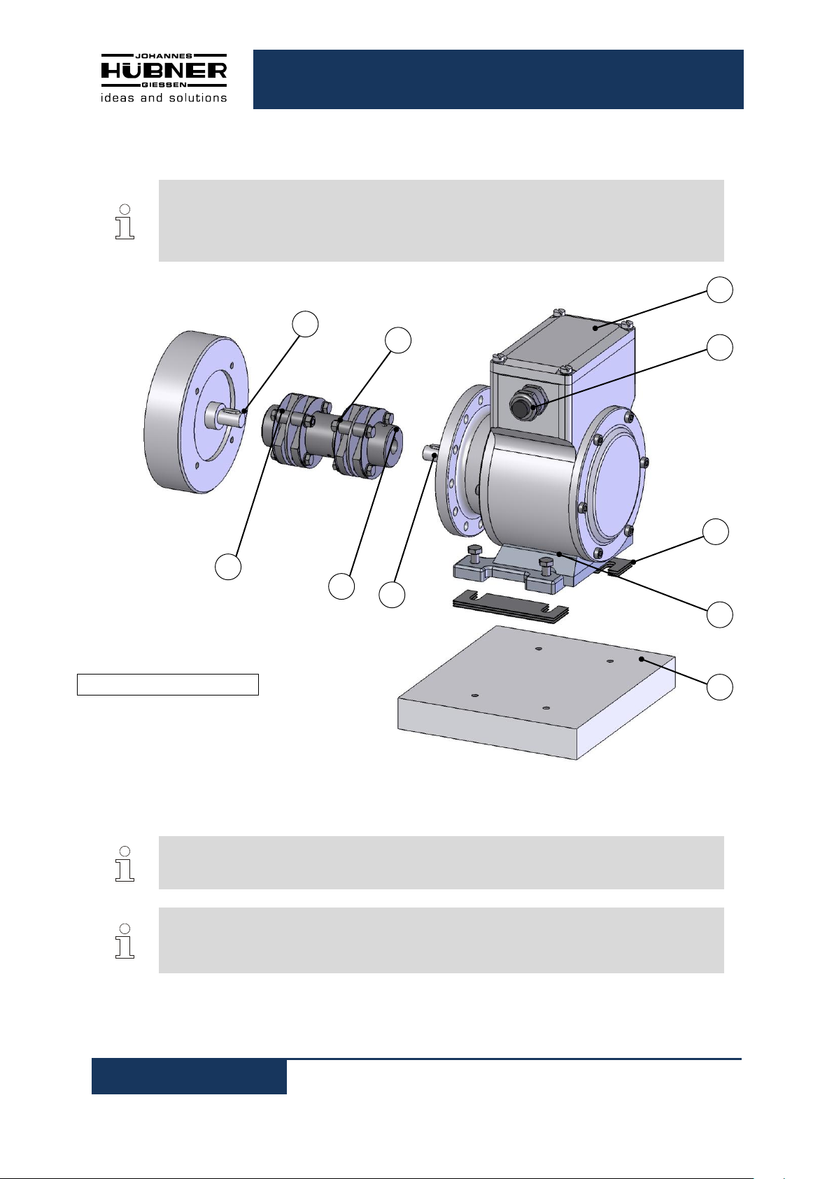
1 2 10
11
17
16
18
20
19
5
Fig.2: EGS 41 construction type B35
4.6 Mounting B35 type (flange and foot)
1. Lightly grease the (motor) shaft (1).
2. Fit coupling (2) onto (motor) shaft.
3. Secure the coupling hub on the (motor) shaft with a grub screw or cheese head screw (10)
(depending on the coupling type).
Electronic Overspeed Switch EGS(H) 41
16
NOTES!
Use shims (19) to achieve the correct vertical alignment to the base plate (20).
Observe information in Chapter 4.7 about mounting errors and max. permissible
mounting tolerances!
NOTES!
To avoid injuries by turning parts, the coupling must be provided before introduction with
a suitable cover.
NOTES!
Angle misalignment and parallel displacement between the (motor) shaft and the
encoder shaft are mounting errors and should be kept as small as possible.
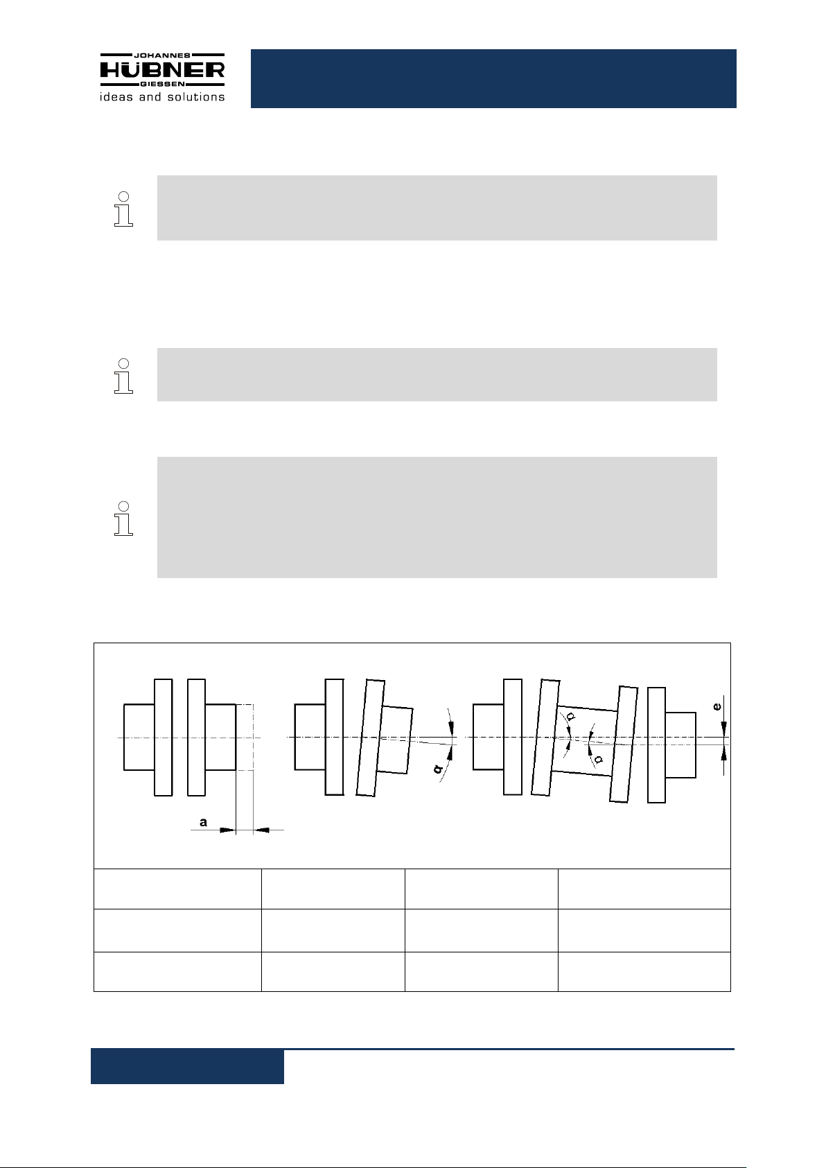
Mounting errors
- Cause radial forces to act on the encoder shaft.
- Reduce the service life of the bearings and the coupling.
- Degrade the quality of the signals (harmonic content).
Coupling
Axial offset a
Angular error α
Parallel offset e
HK 5
± 1 mm
0.5°
-
HKD 5
± 1.5 mm
0.5°
0.5 mm
4. Align the encoder shaft (5) to the (motor) shaft and insert into the coupling hub.
5. Fasten encoder foot with 4 M6 hexagon head screws (18).
6. Secure the coupling hub on the encoder shaft with the grub screw or cheese head screw (11)
(depending on the coupling type).
4.7 Mounting tolerances for Construction Type B5 and B35
Mounting tolerances for our zero-backlash, torsion-resistant couplings HK5 and HKD5:
Electronic Overspeed Switch EGS(H) 41
17
NOTES!
Overspeed switch design types B5/B14 and B35/B14 have a second shaft extension
with integrated coupling half (1) and a B14 type flange (2) on the non-drive end, onto
which it is possible to fit an additional device with a B5 flange, for example an
incremental encoder, absolute shaft encoder or an overspeed switch. A second coupling
half with elastomer ring (5, Figure 4), which is available as an accessory, is required to
fit an additional device.
This design option makes it possible to combine up to three devices.
CAUTION!
Do not remove the housing cover secured with Torx screws! These devices are not
equipped with a second shaft end.
NOTES!
The fastening screws (4) can be used later to secure the additional device (7).
NOTES!
Ensure no liquids or dirt are allowed ingress into the device when the cover plate is
removed.
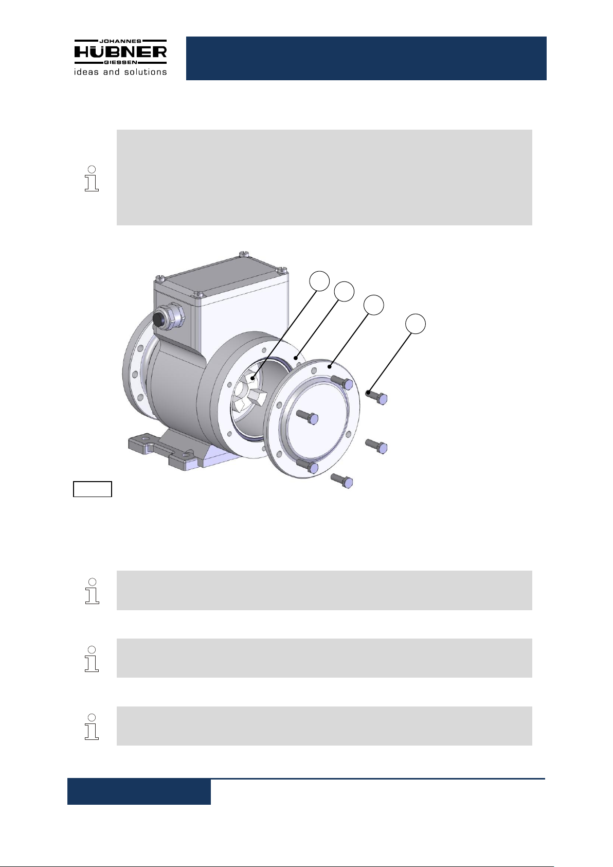
1
2 3 4
Fig.3:
4.8 Attaching additional devices
When supplied ex works the second shaft end is protected by a cover plate (3) secured with 6x M6x20
hexagon head screws (4).
1. Loosen the hexagon-head screws (4).
2. Remove the cover plate (3).
 Loading...