

English
(Assembly) Instructions
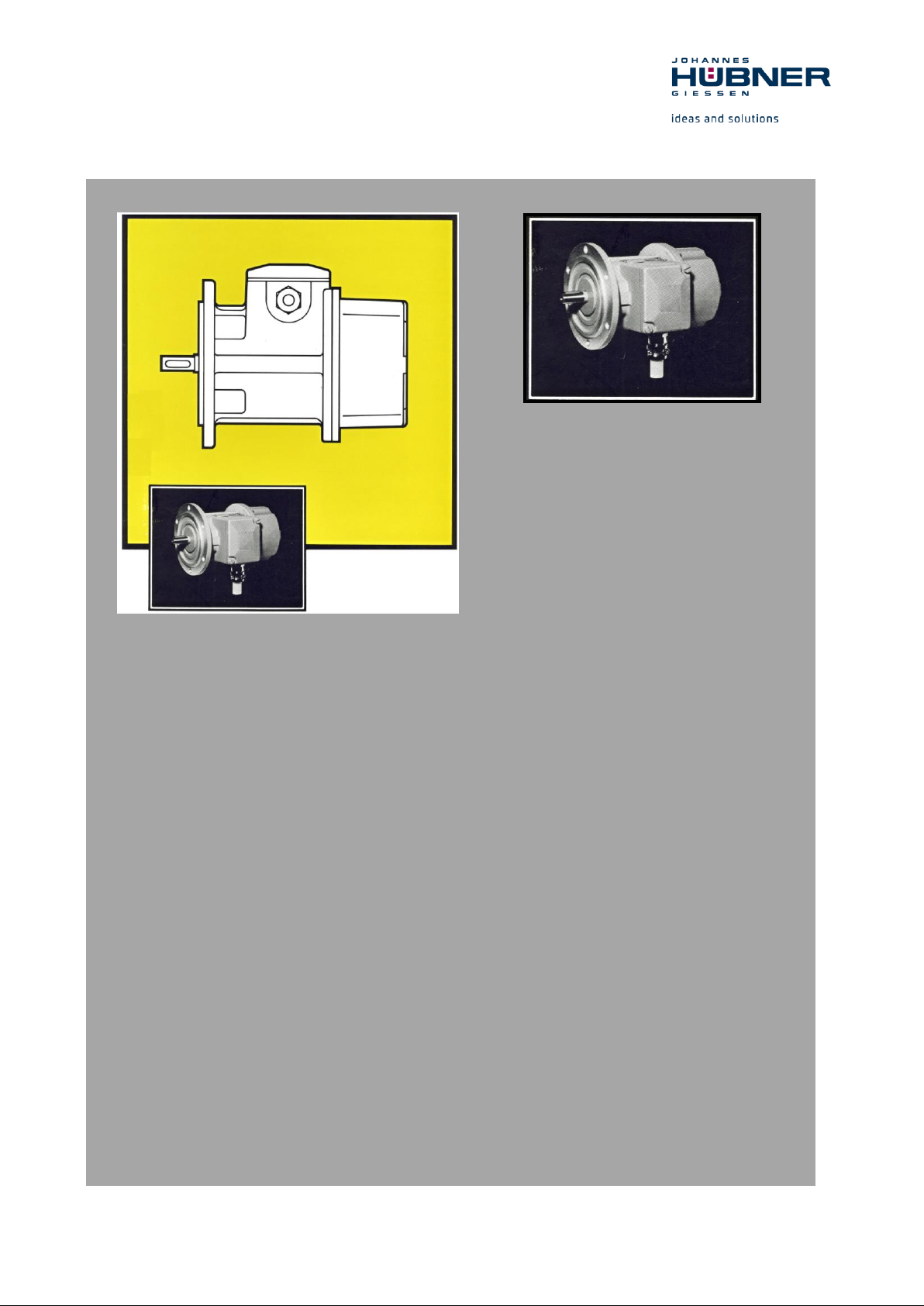
D.C. tachometer generator
TDP 0,7
Read the (assembly) instructions prior to
assembly, starting installation and handling!
Keep for future reference!
Translation of the original Operating and Assembly Instructions BETR-TDP0,7-en_R5(2018-12-20)ID74716 .doc
ID 74716

D.C. tachometer generator TDP 0,7
2
BETR-TDP0,7-en_R5(2018-12-20)ID74716 .doc
Brand names and product names are trademarks or registered trademarks of their respective owner.
Protected trademarks bearing a ™ or ® symbol are not always depicted as such in the manual.
However, the statutory rights of the respective owners remain unaffected.
Manufacturer / publisher
Johannes Hubner
Fabrik elektrischer Maschinen GmbH
Siemensstraße 7
35394 Giessen
Germany
Phone: +49 641 7969 0
Fax: +49 641 73645
E-Mail: info@huebner-giessen.com
www.huebner-giessen.com
Headquarters: Giessen
The manual has been drawn up with the utmost care and attention. Nevertheless, we cannot exclude
the possibility of errors in form and content. It is strictly forbidden to reproduce this publication or parts
of this publication in any form or by any means without the prior written permission of
Johannes Hubner Fabrik elektrischer Maschinen GmbH.
Subject to errors and changes due to technical improvements.
Copyright © Johannes Hubner Fabrik elektrischer Maschinen GmbH
All rights reserved.

D.C. tachometer generator TDP 0,7
3
BETR-TDP0,7-en_R5(2018-12-20)ID74716 .doc
Directory
1 General ......................................................................................................................... 5
1.1 Information about the (assembly) instructions ............................................................ 5
1.2 Scope of delivery ......................................................................................................... 5
1.3 Explanation of symbols ............................................................................................... 5
1.4 Disclaimer .................................................................................................................... 6
1.5 Copyright ..................................................................................................................... 6
1.6 Guarantee terms ........................................................................................................... 6
1.7 Customer service ......................................................................................................... 6
2 Safety ........................................................................................................................... 7
2.1 Responsibility of the owner ......................................................................................... 7
2.2 Intended use ................................................................................................................. 7
2.3 Improper use ................................................................................................................ 7
2.4 Personal protective equipment ..................................................................................... 7
2.5 Personell ...................................................................................................................... 7
2.6 Special dangers ............................................................................................................ 7
2.6.1 Electrical current ............................................................................................................. 8
2.6.2 Rotating shafts and hot surfaces ..................................................................................... 8
2.6.3 Ensure the power supply cannot be reconnected .......................................................... 8
3 Technical Data ............................................................................................................. 9
3.1 Type plate .................................................................................................................... 9
3.2 Type key .................................................................................................................... 10
3.3 Technical Data ........................................................................................................... 10
3.3.1 Dimensions, Power consumption, Environment, Speed ............................................... 10
3.3.2 Elektrical and mechanical data ...................................................................................... 11
3.3.3 General technical data .................................................................................................. 12
4 Construction and Function ......................................................................................... 14
4.1 Block diagram............................................................................................................ 14
4.2 Short description ........................................................................................................ 14
4.3 Connections ............................................................................................................... 14
5 Transport, packaging and storage .............................................................................. 15
5.1 Safety instructions for transport ................................................................................ 15
5.2 Incoming goods inspection ........................................................................................ 15
5.3 Packaging (disposal) .................................................................................................. 15
5.4 Storage of packages (devices) ................................................................................... 15
5.5 Uses ........................................................................................................................... 16
5.6 Place of installation ................................................................................................... 16
5.7 Installation work ........................................................................................................ 17
5.7.1 Installation and commissioning ..................................................................................... 17
5.8 Dismantling ............................................................................................................... 19
6 Disorders .................................................................................................................... 20
6.1 Diagnosis Chart ......................................................................................................... 20
6.2 Inspection and maintenance schedule........................................................................ 22
7 Disposal ...................................................................................................................... 24
7.1 Disposal procedure .................................................................................................... 24

D.C. tachometer generator TDP 0,7
4
BETR-TDP0,7-en_R5(2018-12-20)ID74716 .doc
8 Spare parts .................................................................................................................. 24
9 Annex ......................................................................................................................... 24
9.1 Connection diagram ................................................................................................... 24
10 Dimension drawings .................................................................................................. 25
10.1 Screw tightening torques ........................................................................................ 31
D.C. tachometer generator TDP 0,7
5
BETR-TDP0,7-en_R5(2018-12-20)ID74716 .doc
1 General
1.1 Information about the (assembly) instructions
These (assembly) instructions provide important instructions for working with the device. They must be
carefully read prior to starting all tasks, and the instructions contained herein must be followed.
In addition, applicable local regulations for the prevention of industrial accidents and general safety
regulations must be complied with.
1.2 Scope of delivery
Scope of delivery includes the D.C. tachometer generator TDP 0,7 and the (assembly) Instructions.
1.3 Explanation of symbols
Warnings are indicated by symbols in these (assembly) instructions. The warnings are introduced by
signal words that express the scope of the hazard.
The warnings must be strictly heeded; you must act prudently to prevent accidents, personal injury,
and property damage.
WARNING!
Indicates a possibly dangerous situation that can result in death or serious injury if it
is not avoided.
CAUTION!
Indicates a possibly dangerous situation that can result in minor injury if it is not
avoided.
CAUTION!
Indicates a possibly dangerous situation that can result in material damage if it is not
avoided.
NOTE!
Indicates useful tips and recommendations as well as information for efficient and
trouble-free operation.
Special safety note:
DANGER!
Life-threatening danger due to electric shock!
Indicates a life-threatening situation due to electric shock. If the safety instructions
are not complied with there is danger of serious injury or death. The work that must
be executed should only be performed by a qualified electrician.
D.C. tachometer generator TDP 0,7
6
BETR-TDP0,7-en_R5(2018-12-20)ID74716 .doc
1.4 Disclaimer
All information and instructions in these (assembly) instructions have been provided under due
consideration of applicable guidelines, as well as our many years of experience.
The manufacturer assumes no liability for damages due to:
Failure to follow the instructions in the (assembly) instructions
Non-intended use
Deployment of untrained personnel
Opening of the device or conversions of the device
In all other aspects the obligations agreed in the delivery contract as well as the delivery conditions of
the manufacturer apply.
1.5 Copyright
NOTE!
Content information, text, drawings, graphics, and other representations are protected
by copyright and are subject to commercial property rights.
It is strictly forbidden to make copies of any kind or by any means for any purpose
other than in conjunction with using the device without the prior written agreement of
the manufacturer. Any copyright infringements will be prosecuted.
1.6 Guarantee terms
The guarantee terms are provided in the manufacturer´s terms and conditions.
1.7 Customer service
For technical information personnel is available that can be reached per telephone, fax or email. See
manufacturer´s address on page 2.

D.C. tachometer generator TDP 0,7
7
BETR-TDP0,7-en_R5(2018-12-20)ID74716 .doc
2 Safety
This section provides an overview of all the important safety aspects that ensure
protection of personnel, as well as safe and trouble-free device operation.
If these safety instructions are not complied with significant hazard can occur.
2.1 Responsibility of the owner
The device is used in commercial applications. Consequently the owner of the device is subject to the
legal occupational safety obligations, and subject to the safety, accident prevention, and
environmental protection regulations that are applicable for the device´s area of implementation.
2.2 Intended use
The device has been designed and constructed exclusively for the intended use described here.
Series TDP 0,7 are used for speed monitoring, for instance of electrical and mechanical drives,
hoisting gear, and conveying machines.
Claims of any type due to damage arising from non-intended use are excluded; the owner bears sole
responsibility for non-intended use.
2.3 Improper use
Do not use the device in potentially explosive areas.
The device must not be subjected to mechanical loads in addition to its own weight and
unavoidable vibration and shock loads that arise during normal operations.
Examples for non-permitted mechanical loads (incomplete list):
- Fastening transport or lifting tackle to the device, for example a crane hook to lift a
motor.
- Fastening packaging components to the device, for example ratchet straps, tarpaulins
etc.
- Using the device as a step, for example by people to climb onto a
motor.
It is not permitted to use the device in locations higher than 1000 m above sea level.
2.4 Personal protective equipment
Wear personal protective equipment such as safety shoes and safety clothing to minimise risks to
health and safety when carrying out work such as installation, disassembly or commissioning. Adhere
to all applicable statutory regulations as well as the rules and standards determined by the owner.
2.5 Personell
Installation and commissioning as well as disassembly routines must be carried out by skilled
technical staff only.
2.6 Special dangers
Residual risks that have been determined based on a risk analysis are cited below.
D.C. tachometer generator TDP 0,7
8
BETR-TDP0,7-en_R5(2018-12-20)ID74716 .doc
2.6.1 Electrical current
Danger of death from electricity!
There is an immediate danger of death from contact with live components. Damage to
the insulation or individual components can be lethal.
Therefore: If the insulation is damaged turn off and isolate the power supply
immediately; ensure the insulation is repaired. Before commencing any work on the
electrical installation turn off and isolate the power supply to the installation. Ensure
live components do not come into contact with moisture. Otherwise, this can lead to a
short-circuit.
2.6.2 Rotating shafts and hot surfaces
WARNING!
Risk of injury from rotating shafts!
Touching rotating shafts can result in serious injuries.
Therefore: Do not tinker with moving parts/shafts or work on rotating shafts. Do not
open covers during operations. Ensure no parts are moving before opening any
covers. The encoder can become very hot when operated for longer periods of time.
There is a risk of burns on contact!
2.6.3 Ensure the power supply cannot be reconnected
DANGER!
Danger of death from unauthorized reconnection of the power supply!
There is a risk that the power supply will be reconnected without authorization when
carrying out work, for example when rectifying faults. This represents a serious risk to
the life of those in the danger zone.
Therefore: Turn off and isolate all power supplies to the equipment before
commencing work. Ensure the power supplies cannot be reconnected.

D.C. tachometer generator TDP 0,7
9
BETR-TDP0,7-en_R5(2018-12-20)ID74716 .doc
3 Technical Data
Please note: The details on the nameplate apply exclusively to a purely resistive load. The details
differ for inductive or capacitive loads (please consult the manufacturer).
3.1 Type plate
Fig. 1 type plate
The type plate is located on the side of the housing and contains the following information:
Manufacturer, address
CE mark
S/N = Serial number
Y = year of construction
Rated voltage (DC) [V] / rated speed [rpm]
Imax = maximum current [mA]
nmax = maximum speed [rpm]
IP = degree of protection
ID = Item
Electrical design to VDE 0530
D.C. tachometer generator TDP 0,7
10
BETR-TDP0,7-en_R5(2018-12-20)ID74716 .doc
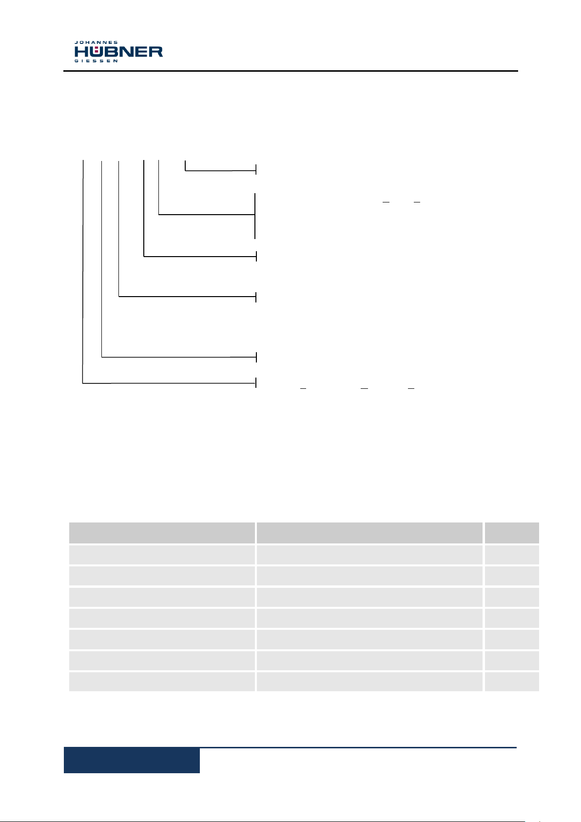
TDP 0,7 /8 – 15 SE spec. (Example)
+ FSE 102 overspeed switch (Optional)
Special version ( version different from normal)
SE (version with magnets Selten-Erd (rare earth)-
magnets for rated voltages > 60 V DC)
K: Temperature compensation
Voltage version (Description 1 – 15)
see Table 1 and 2
Mechanical design
8: HM79 M50953
6: HM79 M50939
HM79 M51240
Size
TDP = Tachometer - Dynamo – Permanenterregt
Indication
Value
Unit
Weight
See chapter 10 dimension drawings /mechanical data
kg
Dimensions
See chapter 10 dimension drawings /mechanical data
mm
Open circuit voltage (DC)
Factor 1,05 to rated voltage/rpm see label on machine
V DC/rpm
Rated voltage with load (DC)
See label on machine
V DC/rpm
Maximum rated current
See label on machine
A DC
Machine-Temperature range
- 40 up to + 100
°C
Maximum speed
See label on machine
rpm
3.2 Type key
3.3 Technical Data
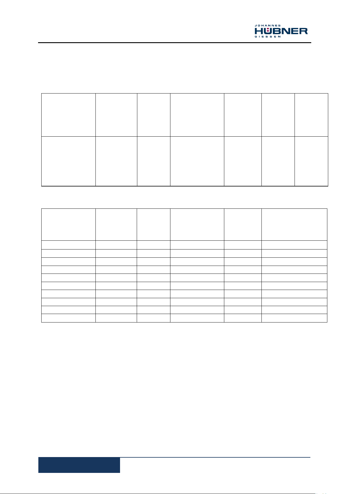
3.3.1 Dimensions, Power consumption, Environment, Speed
D.C. tachometer generator TDP 0,7
11
BETR-TDP0,7-en_R5(2018-12-20)ID74716 .doc
TYPE
Rated
voltage at
1000 rpm
Max.
speed**
Max. permissible.
current at
1000/9000 rpm
Optimum
load
resiatance
Armature-
resistance
at 20 0 C
No loadvoltage at
1000 rpm
[V]
[rpm]
[mA]
[k Ω ]
[Ω]
[V]
TDP 0,7/...-1
10
9000
90/810
1,1
5,4
10,5
TDP 0,7/...-2
20
9000
45/405
4,4
21
21
TDP 0,7/...-3
30
9000
30/270
10
44
31,3
TDP 0,7/...-4
40
9009
22/198
18
93
42
TDP 0,7/...-5
50
9000
18/162
28
128
52
TDP 0,71...-6*
60
9000
15/135
40
180
63
TYPE
Voltage
at
1000
rpm
Maximum
speed
Minimumloadresistance
Armaturereststance
at 20 ° C
Current
Volt
rpm
Ohm
Ohm
mA
TDP 0,7 ...7-SE
70
7700
1200
47
57
TDP 0,7 ...8-SE
80
6750
1600
61
50
TDP 0,7 ... 9-SE
90
6000
2000
58
44
TDP 0,7 ..10-SE
100
5400
2500
95
40
TDP 0,7 ..11-SE
110
4900
3000
115
36
TDP 0,7 ..12-SE
120
4500
3600
138
33
TDP 0,7 ..13-SE.
130
4150
4200
161
31
TDP 0,7 ..14-SE
140
3850
4800
187
29
TDP 0,7 ..15-SE
150
3600
5600
215
27
3.3.2 Elektrical and mechanical data
Table 1: (Standard series)
Table 2: (SE Series)

D.C. tachometer generator TDP 0,7
12
BETR-TDP0,7-en_R5(2018-12-20)ID74716 .doc
U, U
o [ V ]
3.3.3 General technical data
General Information
Magnetic system - external field influence
The magnetic system of this machine consists of two permanent block magnets made from an AINiCo
alloy specially developed for this machine. The direction of magnetisation is determined by the
preferred magnetic orientation.
To guarantee non-ageing operation the permanent magnets are artificially aged until they reach their
optimum remanent density of magnetic energy. Avoid short-circuits because of the unfavourable
effects on the commutator; any burnouts can lead to additional harmonics.
Magnetisation - external field influence
To prevent voltage loss ensure the magnetic circuit of the machine is not interrupted after
magnetising.
Insulation
Insulation class B
Voltage
The listed voltages are detailed in the technical tables. Intermediate values and special voltages
are optional (Option).
Speed / voltage characteristic
n rpm
Terminal connection - polarity
Connecting a two-pole terminal board. When operating the machine in a clockwise direction
(viewing the shaft end) the Ai terminal is positive and the AU terminal is negative.
Carbon brushes / brush holders
The dimensional design and quality of the silver-graphite carbon brushes guarantee a long service
life and maintenance-free operations. The service life of the carbon brushes depends to a large
extent on the condition of the circulating air and the peripheral speed. Under normal operating
conditions the service life is approx. 15 000 operating hours.
Suitable, solid double-type brush holders with increased brush pressure (600 cN/cm2) for DC tachogenerators subjected to vibration and shock loads.
Temperature compensation
There is a reduction in voltage when the temperature increases as a consequence of the temperature
course of the permanent magnet as well as an increase in the internal resistance of the windings. It is
possible to compensate the temperature course of the permanent magnet to a tolerance of
±0.5% per 10 K in the temperature range 0 to +100 °C (Option).
.
Harmonics
A low percentage harmonic content (distortion) across a large speed range is a significant
characteristic of a good tacho voltage. The r.m.s. value of the overall mix of harmonics is generally
measured using a thermionic voltmeter and considered in relation to the DC voltage.
This value is approx. 3‰ at a speed between 100 to 3000 rpm.
Machine related harmonics result from the construction, electrical design and utilisation as well as
production asymmetries.
Assembly related harmonics (single and double speed frequency) are caused by angular
misalignment and parallel displacement.
Ensure precisely centred assembly, in particular in conjunction with B 3.
Align added device referring to a harmonics oscillogram (<5‰).

D.C. tachometer generator TDP 0,7
13
BETR-TDP0,7-en_R5(2018-12-20)ID74716 .doc
Linearity
The suitability of a tacho-generator for widely varying control tasks is determined by the linear
relationship between the output voltage and speed.
Optimum load current and armature reaction
The max. permissible load current for the respective machine type is detailed in the table, which with
the linearity error should not be exceeded.
Linearity error values can reach 5‰ if the tacho-generator is operated at max. current loads. For very
precise control tasks of applications requiring a speed deviation range of 1‰ it is recommended to
choose the value detailed in the table for optimum load resistance as terminal resistance. These
relatively high ohmic terminal resistances ensure that just 1/10 of the maximum current is allowed to
flow. As a consequence, the armature reaction, which acts as the flux-weakening component when
higher currents flow, will be weakened by a factor of 10. This in turn means there will be no noticeable
field distortion resulting from armature reaction.
Brush contact voltage
DC tacho-generators are generally fitted with silver-graphite carbon brushes, which exhibit a very low
brush contact voltage. The total voltage drop at the sliding contact of the carbon brush/commutator
depends on the peripheral speed, current density below the brushes, brush pressure and the
characteristic build-up of patina on the brush contact surface.
Degree of protection to DIN VDE 0530 Part 5
This machine is designed to degree of protection IP 55, is completely enclosed and protected against
low pressure jets of water from all directions and the build-up of harmful deposits of dust.
Special degree of protection IP 56 when the shaft is sealed with an axial sealing ring (extra
charge). Max. speed 4000 rpm.
Shaft ends - shaft seals
The cylindrical shaft ends with Ø11 are machined with a closed keyway to DIN 6885 Blatt 1 (key
included in scope of supply). Special shafts with Ø7 and Ø6 available.
It is possible to seal all tacho-generators with a sealing ring on the drive side; this is generally fitted
when adding a speed increasing gear.
Bearings
All designs are equipped with sealed and lubricated for life deep groove ball bearings.
Design Fixed bearing DS (drive side)
B 3, B 5 6201 LLU
Coating - surface protection
Light-grey coating RAL 7030.
In addition to special insulation an appropriate protective coating is applied to tacho-generators
exposed to aggressive gases and vapours.
Accessories
To maintain the degree of protection class rating IP 55 and IP 56 we use skin-tight cable glands
SR-1109 Pg 11 for connection cables Ø 7.5-9 mm.

D.C. tachometer generator TDP 0,7
14
BETR-TDP0,7-en_R5(2018-12-20)ID74716 .doc
Electrical connection:
Clockwise rotation: A1 terminal positive
A2 terminal negative
Winding test (repeat) max. 500 V
Suitable connection cable to maintain degree of
protection
Fit cover plate and terminal box lid,
machine is ready for operations!
A1 (+) A2 (-)
4 Construction and Function
4.1 Block diagram
Fig. 2: Block diagram clockwise rotation
4.2 Short description
The DC-Tacho-Generator TDP consists of a permanent
magnet stator for excitation and a rotor from which DC
voltage is drawn via carbon brushes. The rotating rotor
generates a DC voltage at a given linear relationship in
proportion to its speed.
4.3 Connections
The terminal box is fitted with cable glands. Suitable cables
(Pg 11, cable Ø 7.5-9) are necessary to maintain the degree
of protection.
D.C. tachometer generator TDP 0,7
15
BETR-TDP0,7-en_R5(2018-12-20)ID74716 .doc
5 Transport, packaging and storage
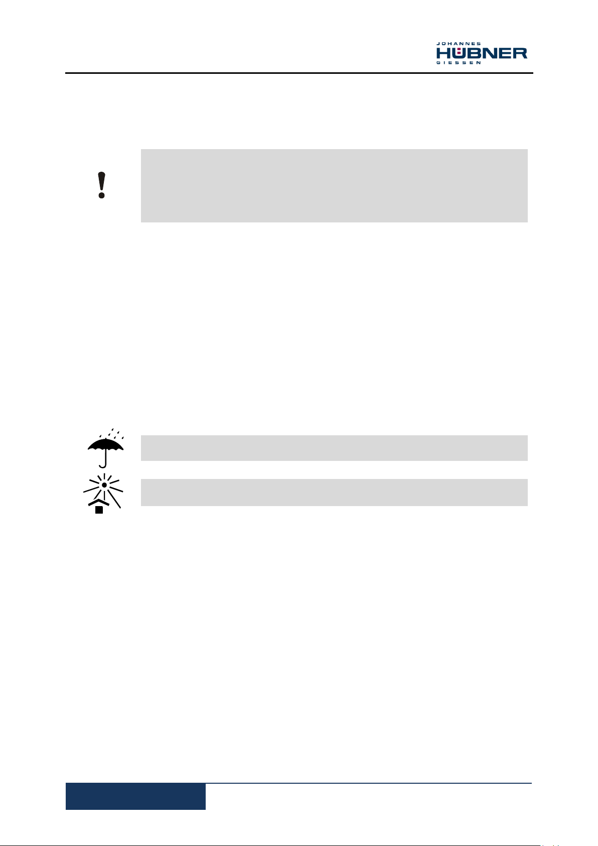
5.1 Safety instructions for transport
CAUTION!
Improper transport can cause property damage!
Comply with the symbols and warnings on the packaging.
Handle with care
Protect from moisture
Protect from heat over 40°C and direct sunlight
5.2 Incoming goods inspection
Check delivery immediately upon receipt for completeness and possible transport damage.
Inform the forwarder directly on receipt of the goods about existing transport damages (prepare
pictures for evidence).
5.3 Packaging (disposal)
The packaging is not taken back and must be disposed of in accordance with the respective statutory
regulations and local guidelines.
5.4 Storage of packages (devices)
Protect from moisture
Keep packed goods dry and protected against moisture.
Protect from heat
Protect packaged goods from heat over 40°C and direct sunlight.
If stored for longer periods (> 6 months) we recommend sealing the devices in foil, possibly with a
desiccant.

D.C. tachometer generator TDP 0,7
16
BETR-TDP0,7-en_R5(2018-12-20)ID74716 .doc
5.5 Uses
DC-Tacho-Generators from the series TDP 0.7 are used to convert rotary motion (rpm) to DC
voltage in proportion to the rotating speed. These encoders are suitable for deployment with
larger industrial drives such as those used in steel and rolling mills, in coal mining operations, in
process technology, in railway systems, in power plants, in marine engineering and so on.
5.6 Place of installation
Installation height < 1000 m above msl. Consult the manufacturer if the installation height is >
1000 m (possible derating)
Permissible ambient temperature - 40 °C to + 100 °C.
Avoid too dry ambient conditions (ensure patina build-up on carbon brush/commutator).
Observe details on nameplate (ratings, protection class and so forth) when operating the DC
tacho-generator.
Do not attach or lean temperature sensitive components onto or against the machine; do not
position such components in the immediate vicinity of the machine.
Ensure sufficient space is available for maintenance work (please refer to 8.2 Inspection and
maintenance schedule)
We recommend installing a canopy for model designs and shaft ends facing downwards; fit a
cover on the plant side if the shaft end faces upwards.
The owner must ensure that no system resonance or vibration arise from interaction between
the machine and plant that could impair the functioning of the machine or result in damage to
the machine or the entire plant or accelerate the ageing process (of the bearings, for
example).
It is the owner's responsibility to undertake suitable measures at the place of installation that
ensure the devices and plant in their totality fulfil the relevant standards applicable to
electromagnetic compatibility.

D.C. tachometer generator TDP 0,7
17
BETR-TDP0,7-en_R5(2018-12-20)ID74716 .doc
5.7 Installation work
! Caution!
- It is the owner's responsibility to ensure that
all moving parts are properly safeguarded and
ensure that the machine is safe to operate!
- Observe the max. permissible voltage when
repeating the winding test (contact the
manufacturer).
- It is essential to prevent the ingress of oil or
grease into the commutator area! Oil mist as
well as touching the carbon brushes with oily
fingers will cause the carbon brushes to wear
significantly; this in turn will lead to the
commutator becoming greasy and shortcircuits between the segments.
5.7.1 Installation and commissioning
Please note:
- It is the owner's responsibility to ensure that all moving parts are properly
safeguarded and ensure that the machine is safe to operate!
- Observe the max. permissible voltage when repeating the winding test (contact
the manufacturer).
- It is essential to prevent the ingress of oil or grease into the commutator area!
Oil mist as well as touching the carbon brushes with oily fingers will cause the
carbon brushes to wear significantly; this in turn will lead to the commutator
1. Use a zero-play coupling. The armature must rotate easily; the carbon brushes must sit
properly in the brush holders.
2. Ensure precisely centred assembly. Angular misalignment and parallel displacement
lead to additional harmonics. Align added device referring to a harmonics oscillogram
(<5‰). Fit and align overhanging devices with due care and attention. Observe
maximum permissible radial eccentricity 0.05 mm. Do not allow radial or axial forces to
act on the tacho-generator shaft.
3. Secure machine using flange or foot.
Mount the machine securely without distortion and not subject to vibration. Securely
fasten the feet or flange using standard screws and washers in all of the through holes. It
is important to ensure the correct property class, size and length of engagement on the
fastening side (in accordance with VDI 2230 Blatt 1) so that the entire system remains
securely and reliably mounted under all operating statuses. The thread engagement, its
stability and strength on the fastening side must be guaranteed at all times.
The screws must be tightened to the appropriate torque for the property class and
thread; screws must not become loose when the machine is in operation or at a
standstill. Use a torque wrench. Regularly check the fastening screws are seated
correctly in accordance with the inspection and maintenance schedule. Use only flexible
couplings; align and adjust the tacho-generator exercising due care and attention.
Fit coupling components or other fastenings with due care and attention. Support the
opposite end of the shaft (blows will damage the bearings).
becoming greasy and short-circuits between the segments.

D.C. tachometer generator TDP 0,7
18
BETR-TDP0,7-en_R5(2018-12-20)ID74716 .doc
If the second shaft is not used secure the key permanently to ensure it cannot be thrown out
of the keyway.
4. Connections in the terminal enclosure.
Check the load against the technical data detailed on the nameplate. Please note: Take
account of surge protectors for downstream devices, if these are connected to the output
voltage of the tacho-generator. The output voltage of the tacho-generator increases at a
given (linear) relationship in proportion to the speed.
● Connect according to circuit diagram (see wiring diagram).
● To guarantee a safe electrical connection the cross-section of the conductors must be
sized in accordance with the rated current as detailed on the nameplate.
● Ensure any unused cable glands and the terminal box are sealed dust and water-tight
● Create a safe earth connection!
Before closing the terminal box you must ensure that
● The connections have been terminated according to the wiring diagram.
● All connections in the terminal box have been securely tightened.
● All minimum clearance values have been maintained (greater than 8 mm up to 500 V,
greater than 10 mm up to 750 V)
● The inside of the terminal box is clean.
● Unused cable glands are sealed and the screw plugs including the seals are tightened
securely.
● The gasket seal is clean and properly glued in the lid of the terminal box; ensure all
sealing surfaces are in a proper condition to guarantee the degree of protection.
● The rating data match the data detailed on the nameplate.
5. Remove any transport locks before commissioning.

D.C. tachometer generator TDP 0,7
19
BETR-TDP0,7-en_R5(2018-12-20)ID74716 .doc
5.8 Dismantling
Observe and adhere to safety information (2)!
Shut down and ensure the machine cannot be restarted.
Turn off and isolate the power supply; turn off and isolate the power supply to any
additional or auxiliary circuits.
Ensure adjacent live components are insulated and safeguarded.
Examine components for damage and broken edges (for example risk of cuts from
broken off foot).
Exercise due care and attention when removing coupling parts and fastenings; support
the opposite end of the shaft (blows will damage the bearings). Coat the shaft with a thin
layer of oil and seal with screw cap. Ensure the terminal box and cable glands are
sealed dust and water-tight; ensure the degree of protection (see nameplate) is achieved
and guaranteed for transport.
Observe and adhere to transport information (5)!
Ensure that the packaging (carton + palette) used to transport the machine is correctly
sized and that the machine is secured by the packaging in such a manner that forces
resulting from the weight of the machine during transport cannot cause any damage to
the machine, to neighbouring parts or injury to personnel! Use transport locks to reduce
the load acting on the bearings.
Dismantling (disassembly / removing the armature) the fully assembled tacho-generator
TDP 0.7 must always be undertaken by the manufacturer only.
D.C. tachometer generator TDP 0,7
20
BETR-TDP0,7-en_R5(2018-12-20)ID74716 .doc
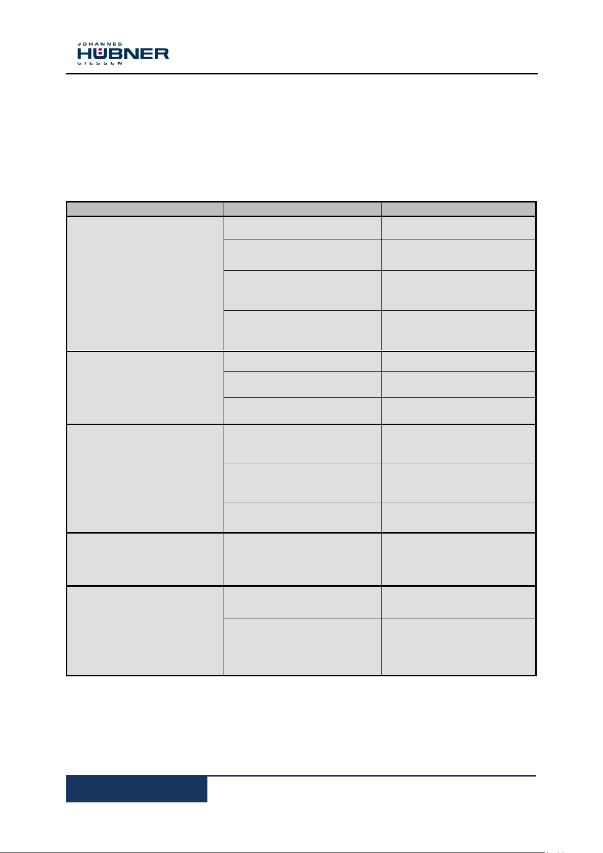
Disturbance
Possible cause
Troubleshooting
Voltage to low
Wrong speed
Speed measurement control
Winding short
Voltage check Consulting
producer
Maximum permissible current
is exceeded
Reduce current.
Irrreversibler damage the
magnets (aging)
Magnets magnetize new
(consult manufacturer).
Voltage values at different
rotation unequal
Neutral zone adjusted.
Consulting producer
Bias excitation field by
armature reaction.
Consulting producer
Reversion, tilt the brush in
the holder.
Consulting producer
Harmonics
Burn marks on the
commutator, for example by
short circuits.
Cause for short circuits and
repair
Coupling or assembly errors
(misalignment and parallel
misalignment).
Correct the mounting
mistake
System-related vibrations
and resonance
Possible causes, contact the
manufacturer.
Rotor rotating hard
Armature short circuit,
defective storage
Decouple machine to look
again, a hard place?
Contact the manufacturer.
Grinding noise
Carbon brush holder from
fallen.
Brush back into holder,
avoid strong vibrations.
Rotating parts sand.
Grinding cause notice.
If possible! Remove foreign
matter otherwise contact
manufacturers.
6 Disorders
In disorders that can not be eliminated by the following
instructions, the manufacturer is looking for, see service
address on page 2.
6.1 Diagnosis Chart
D.C. tachometer generator TDP 0,7
21
BETR-TDP0,7-en_R5(2018-12-20)ID74716 .doc
Bearing makes noise or is
jammed
Note:
Exchange of the bearings
only by the manufacturer.
Mounting error / clutch
problem
Mounting precision check
Corroded bearings
Replace bearing by
manufacturer
Insufficient lubrication.
contact the manufacturer.
Too little/much bearing play.
Replace bearings
Contact the manufacturer
Grind marks in the bearing
track, scoring.
Replace bearings; contact
the manufacturer.
Bearing jammed or distorted
Check bearing bore
contact the manufacturer.
Seals rub
Replace seal.
Please contact the
manufacturer
Insufficient lubrication
Please contact the
manufacturer
Bearing corroded
Please contact the
manufacturer.
Too little bearing play
Please contact the
manufacturer
Coupling pushes or pulls
Re-align machine
Belt tensioned too tightly
Adjust belt pulley in line with
specifications.
Bearings jammed or distorted
Contact the manufacturer
Heavy vibration
Rotor imbalance, rotor not
round, shaft distorted
Please contact the
manufacturer
Incorrect alignment
Align set of machines; check
coupling.
Imbalance with the coupled
prime mover
Rebalance the coupled
prime mover
Shocks from coupled
prime mover
Check prime mover
Resonance in the
foundations
Strengthen foundations
following consultation with
the manufacturer
Changes in the foundation
Following consultation with
the manufacturer determine
the cause, eliminate error
and realign the machine.
Carbon brushes wearing
excessively
Brush contact resistance too
high – badly formed patina
(brush contact face -
Change condition of
circulating air
(remedy lack of moisture;

D.C. tachometer generator TDP 0,7
22
BETR-TDP0,7-en_R5(2018-12-20)ID74716 .doc
commutator contact face) as
a result of the air being too
dry.
avoid dust in ambient air).
Brush pressure too high
Contact the manufacturer.
Grease on brush contact face
Clean contact face (contact
the manufacturer)
Heavy vibration
* See above.
Surface temperature too high
(>100 °C)
Operated under short-circuit
conditions
Check device; please
contact the manufacturer.
Other faults
Please contact the
manufacturer.
PLEASE NOTE!
No other actions are required to be carried out
on the device in addition to the following
cyclical inspections described in this inspection
schedule. Any attempt to tamper with the
device will result in the warranty being declared
null and void!
Interval
Inspections
To be carried out by
Regularly
Check fastening screws are seated
correctly
Skilled personnel
After approx. 2000 operating
hours
Check carbon brushes; blow carbon
brush dust out of the machine using dry,
oil-free compressed air; check ease of
movement. When changing carbon
brushes (service life approx. 10 000 –
20 000 operating hours depending on
environmental conditions and speed)
ensure the new brushes are of the same
quality and type. Please note: Double
tacho-generators have 2 commutators
and 2 brush rockers).
Skilled personnel
After approx. 2000 operating
Clean soiled commutators using a clean,
Skilled personnel
6.2 Inspection and maintenance schedule
Caution! Replace the sealing ring on special versions (tacho-generators with speed increasing gear)
after 5000 to 8000 hours of operation. Blow out metal filter of tacho-generators designed with
ventilation vents (IP 55 spec.).
Contact the manufacturer when operating any other special version and combinations of devices (e.g.
TDP 0.7 + FSE 102).

D.C. tachometer generator TDP 0,7
23
BETR-TDP0,7-en_R5(2018-12-20)ID74716 .doc
hours
oil-free cloth. Do not remove smooth
patina build-up from contact face.
Remove grooves and polish surface
using fine Emery cloth or skim on lathe
(possibly recut and duburr slots).
Every 48 months
Check ball bearings for noise, running
smoothly. Service life approx. 20 000
hours (lubricated for life); however,
service life depends on speed,
environmental conditions and load.
Caution! Do not remove the armature
before short-circuiting the magnetic
circuit using an appropriate shortcircuiting ring (otherwise voltage drop of
approx. 25%). Observe dismantling
instructions!
Bearings must be replaced
by the manufacturer or a
certified workshop only.
Regularly (depending on degree
of soiling)
Cleaning:
Blow-clean the machine using dry, oil-
free compressed air. Do not use
cleaning agents that damage the
coating. Do not use inflammable
cleaning agents.
Skilled personnel
Regularly
Check coating.
If the protective coating is
sufficiently damaged, repaint to
prevent risk of corrosion
(recommended).
Skilled personnel
If the machine has not been in
use for a long time (more than 6
months).
Check the insulation resistance of the
windings (greater approx. 1-5 megaohm). To measure the insulation
resistance disconnect all outgoing lines
from the generator. Contact the
manufacturer if the resistance reading is
less than 1 mega-ohm.
Skilled personnel

D.C. tachometer generator TDP 0,7
24
BETR-TDP0,7-en_R5(2018-12-20)ID74716 .doc
NOTE!
When ordering spare parts, always state the serial number of the
device!
TDP 0,7 …
Clamping strip (Terminal box):
Electrical connection:
Clockwise rotation: A1 terminal positive
A2 terminal negative
Winding test (repeat) max. 500 V
Suitable connection cable to maintain degree of
protection
Fit cover plate and terminal box lid,
machine is ready for operations!
7 Disposal
7.1 Disposal procedure
The manufacturer is not obliged to take back the device.
The device is classed as electronic equipment and subject to the WEEE Directive; observe local,
country-specific laws when disposing of the device.
For information on environmentally sound disposal please contact your local authority or a specialist
disposal company.
8 Spare parts
Spare parts are available on demand via the service address on page 2.
9 Annex
9.1 Connection diagram

D.C. tachometer generator TDP 0,7
25
BETR-TDP0,7-en_R5(2018-12-20)ID74716 .doc
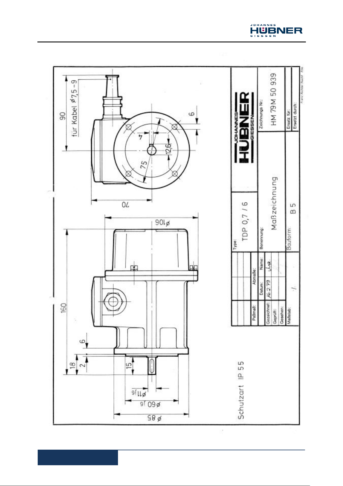
10 Dimension drawings

D.C. tachometer generator TDP 0,7
26
BETR-TDP0,7-en_R5(2018-12-20)ID74716 .doc
D.C. tachometer generator TDP 0,7
27
BETR-TDP0,7-en_R5(2018-12-20)ID74716 .doc

D.C. tachometer generator TDP 0,7
28
BETR-TDP0,7-en_R5(2018-12-20)ID74716 .doc

D.C. tachometer generator TDP 0,7
29
BETR-TDP0,7-en_R5(2018-12-20)ID74716 .doc

D.C. tachometer generator TDP 0,7
30
BETR-TDP0,7-en_R5(2018-12-20)ID74716 .doc

D.C. tachometer generator TDP 0,7
31
BETR-TDP0,7-en_R5(2018-12-20)ID74716 .doc
Weight TDP 0,7: approx. 2,5 kg / mass moment of intertia: 0,44 kgcm².
10.1 Screw tightening torques
Screws used to mount the machine (screw material, the material pairings to be fastened and the
length of thread engagement) are to be calculated to VDI 2230 (Page 1). The materials used and the
construction to which the generator is to be fastened must guarantee a permanently secure and
reliable joint. The owner is obliged to inspect and ensure compliance with all specifications.
 Loading...