

Hubitron Steueungstechnik HBG 800-DP Operating Manual
Operating manual HBG 800-DP Rev. 05 - 08/18 Hubitron Steuerungstechnik
Hubitron Steuerungstechnik, Hauptstr. 4/1, D-89611 Obermarchtal, Germany, Tel. +49(0)7375/922066, FAX +49(0)7375/922077 1 of 16
Operating manual
Wireless hand wheel unit HBG 800-DP
Content
1. Description ..................................................... 2
2. Technical Data................................................ 2
2.1 Hand terminal HBG 800-DP ............................ 2
2.2 Access point HBG 800-DP...............................2
2.3 Charging station ...............................................2
2.4 Connecting Adaptor HBG 800-DP ...................2
2.5 System timing...................................................2
2.5.1 Emergency stop + safety buttons ..............2
2.5.2 All other buttons .......................................2
3. Scope of delivery ........................................... 2
4. Machine demands.......................................... 2
5. Environmental conditions............................. 2
5.1 Kind of conditions ............................................2
5.2 Tolerance range ................................................2
6. Operating elements ....................................... 3
6.1 Hand terminal HBG 800-DP ............................ 3
6.2 Accesspoint HBG 800-DP................................3
6.3 Charging station ...............................................4
6.4 Connecting adaptor HBG 800-DP ....................4
6.4.1 Address of Profibus ..................................4
6.4.2 Pin assignment..........................................5
7. Installation ...................................................... 5
7.1 Profibus installation..........................................5
7.2 Out of operation................................................6
8. Operation ........................................................ 6
8.1 Switching on and off of the hand terminal .......6
8.2 LCD display .....................................................6
9. Set up...............................................................6
9.1 Used buttons .................................................... 6
9.2 Enter Set up ..................................................... 6
9.3 Change Set up .................................................. 6
9.4 Description of the menue points ...................... 7
9.5 Test routines .................................................... 7
9.6 Set up overview ............................................... 7
10. Start of operation............................................8
10.1 Channel selection............................................. 8
10.1.1 Field strength measurement ..................... 8
10.2 Set transmitting power ..................................... 8
10.3 Set minimum level ........................................... 8
11. Actions to avoid interruptions ......................8
12. Error solutions................................................9
12.1 Possible errors.................................................. 9
12.2 Cause of errors................................................. 9
12.3 LOW - BATT display ...................................... 9
12.4 No function ...................................................... 9
13. Maintenance and care ..................................10
13.1 Change of rechargeable batteries ................... 10
13.1.1 Exchange of rechargeable batteries........ 10
14. Frequency table ............................................11
15. Safety instructions .......................................11
16. LED's in the access point ............................12
16.1 LED's in the connecting adaptor .................... 12
17. Spare parts....................................................13
18. EG Declaration of Conformity .....................14
Appendix ...............................................................15
Profibus – Module description................................... 15
Connecting example Siemens 810D/840D ................ 16

Operating manual HBG 800-DP Rev. 05 - 08/18 Hubitron Steuerungstechnik
Hubitron Steuerungstechnik, Hauptstr. 4/1, D-89611 Obermarchtal, Germany, Tel. +49(0)7375/922066, FAX +49(0)7375/922077 2 of 16
1. Description
The radio controlled hand wheel HBG 800-DP is for
wireless control of CNC machines which control
units has a Profibus interface implemented, e. g.
Siemens Sinumerik 810D, 840D. It replaces most of
the functions of the original Siemens BHG.
The safety functions (emergency stop + approval
button) fulfil the safety category 3, EN954-1. The
concept is approved by the German Institute for
Health and Safety - BGIA.
The system is exclusively designed for
operation within the European market! Other
markets require a written approval of the
manufacturer!
2. Technical Data
2.1 Hand terminal HBG 800-DP
Dimensions (l x w x h) ............... approx. 220x116x80
Weight ................................................... approx. 620g
Power supply........... 3 x NiMh rechargeable batteries
Display ...........................................LCD, 2 x 12 digits
.................................................................... 11 LED‘s
Operating elements................................... 16 buttons
......................................................... 2 safety buttons
........................................... 1 emergency stop button
.........................................................1 rotary encoder
........................................................2 potentiometers
Operating time ..........................................> 24 hours
Frequency band ............433 + 869 MHz (SRD 1e/1k)
Channels ................................................................ 21
RF power............................. max. 10mW at 433 MHz
..............................................max. 5mW at 869 MHz
Range................................ approx. 25 m (adjustable)
Vibration alarm ..................................................... yes
2.2 Access point HBG 800-DP
Dimensions (l x w x h) ........... approx. 220 x 130 x 70
Weight .................................................. approx. 1,4kg
Power supply..........................via connecting adaptor
Outputs............ 2 x emergency stop, each 3A, AC-15
............................. 2 x safety button, each 2A, AC-15
..........1 charging output for hand terminal 20/240mA
Inputs ........2 x emergency stops for charging station
Frequency band .................................433 + 869 MHz
Channels ................................................................ 21
RF power............................. max. 10mW at 433 MHz
..............................................max. 5mW at 869 MHz
Range................................ approx. 25 m (adjustable)
2.3 Charging station
Dimensions (l x w x h) ............. approx. 190 x 95 x 55
Weight ................................................... approx. 100g
Contacts ................................................................... 4
2.4 Connecting Adaptor HBG 800-DP
Dimensions (l x w x h) .............approx. 122 x 90 x 60
Weight..........................................................ca. 130 g
Power supply ............................. 24V DC ±15%, 0,5A
Connections........................................Profibus DPV1
....................................... emergency stop, (2 circuits)
..........................................................2 safety buttons
............................................................... access point
Mounting ................................................... on DIN rail
2.5 System timing
2.5.1 Emergency stop + safety buttons
min. 23,2 ms
max. 155 ms
average reaction: approx. 31 ms
2.5.2 All other buttons
min. 21 ms
max. 142 ms
average reaction: approx. 27 ms
3. Scope of delivery
1 hand terminal HBG 800-DP
1 access point HBG 800-DP
1 connecting adaptor HBG 800-DP
1 charging station
2 antennas
1 connecting cable 16 pol. 3m
1 mounting set + adhesive symbols for front foil
4. Machine demands
o The control unit of the machine must have a
working Profibus interface.
o An emergency stop must be stored at the
machine if the emergency stop relay shows
different levels.
o An emergency stop must be confirmed at the
machine control.
o The power supply has to comply with EN 50178
and IEC 742 (safe interruption from the power
outlet, protection of over voltage, PELV).
o A machine movement directed by the hand
wheel is only allowed, if both safety buttons are
pushed and have been opened before!
o A hard wired emergency off on the machine is
imperative!
5. Environmental conditions
5.1 Kind of conditions
The wireless hand wheel is exclusively constructed
for the operation in closed plants. Direct sun light
rays are harmful and can cause damage.
The protection classification rating is IP 64.
5.2 Tolerance range
Operating temperature: +5° to +45°C
Storage temperature: -20° to +70°C
max. humidity: 90%, no condensation
Vibration resistance: 5g
Shock resistance: 10g
Operating manual HBG 800-DP Rev. 05 - 08/18 Hubitron Steuerungstechnik
Hubitron Steuerungstechnik, Hauptstr. 4/1, D-89611 Obermarchtal, Germany, Tel. +49(0)7375/922066, FAX +49(0)7375/922077 3 of 16
6. Operating elements
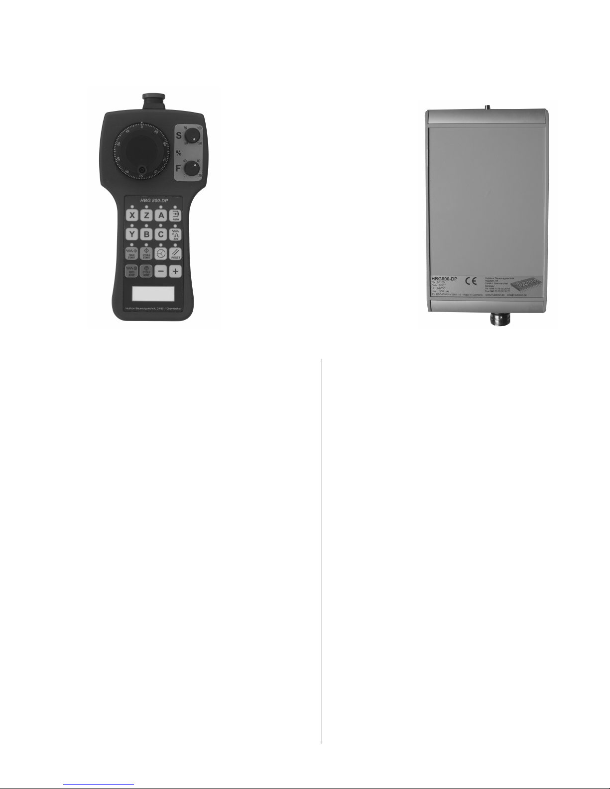
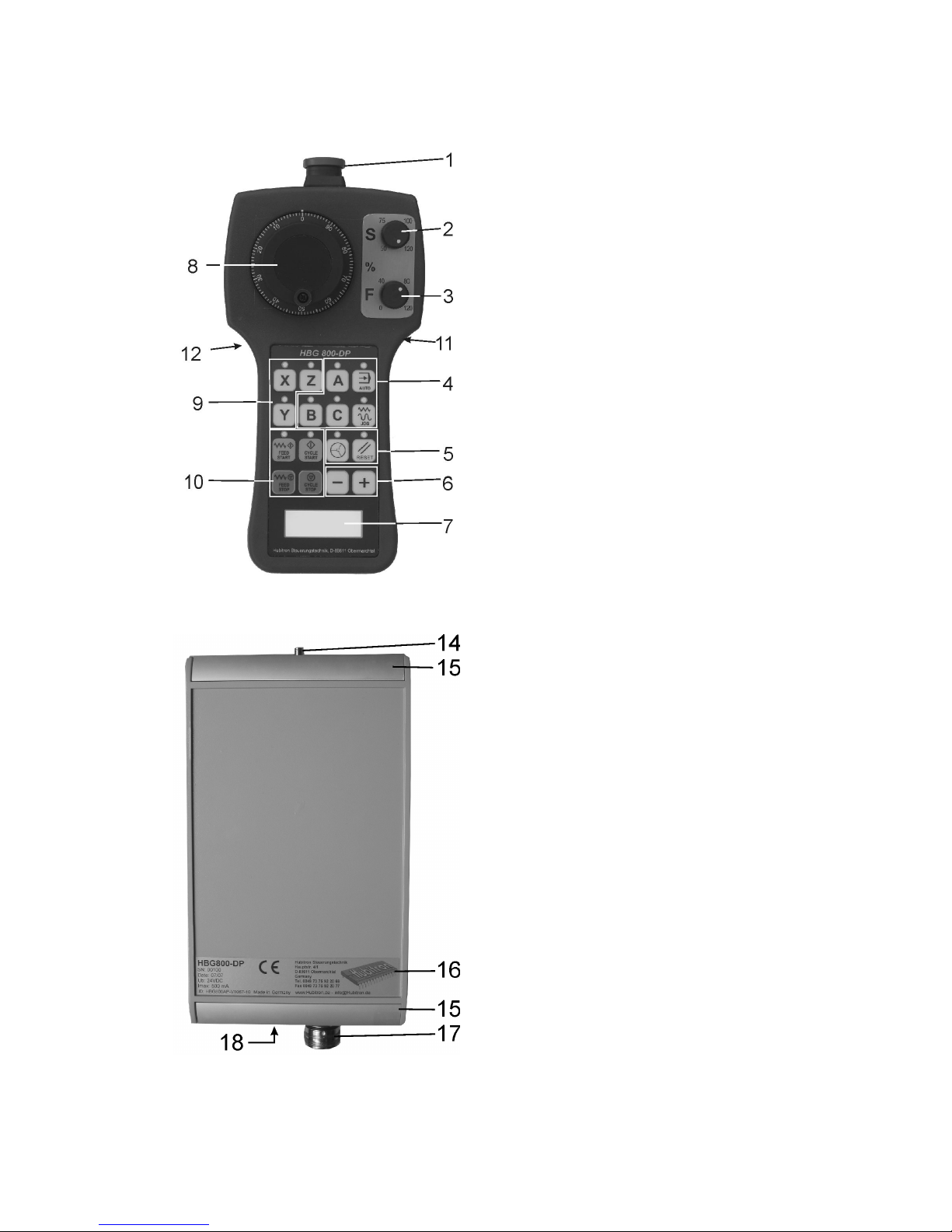
6.1 Hand terminal HBG 800-DP
1 emergency stop button
2 potentiometer 1 (spindle)
3 potentiometer 2 (feed)
4 5 free programmable buttons with LED‘s (free
symbol definition)
5 button for hand wheel + inching function with
LED's
6 axis movement buttons
7 LCD display
8 encoder
9 axis selection buttons with LED‘s
10 feed + spindle start/stop (the stop buttons are
working as break contacts, this can be changed
in the setup)
11 safety button 1
12 safety button 2
On the backside is a magnet with hook, charging
contacts and the label.
6.2 Access point HBG 800-DP
14 antenna socket X3
15 covers
16 type label
17 connection X1 to connecting adaptor
18 socket for charging station X2
Remark: The mounting holes are underneath the
covers!
Operating manual HBG 800-DP Rev. 05 - 08/18 Hubitron Steuerungstechnik
Hubitron Steuerungstechnik, Hauptstr. 4/1, D-89611 Obermarchtal, Germany, Tel. +49(0)7375/922066, FAX +49(0)7375/922077 4 of 16
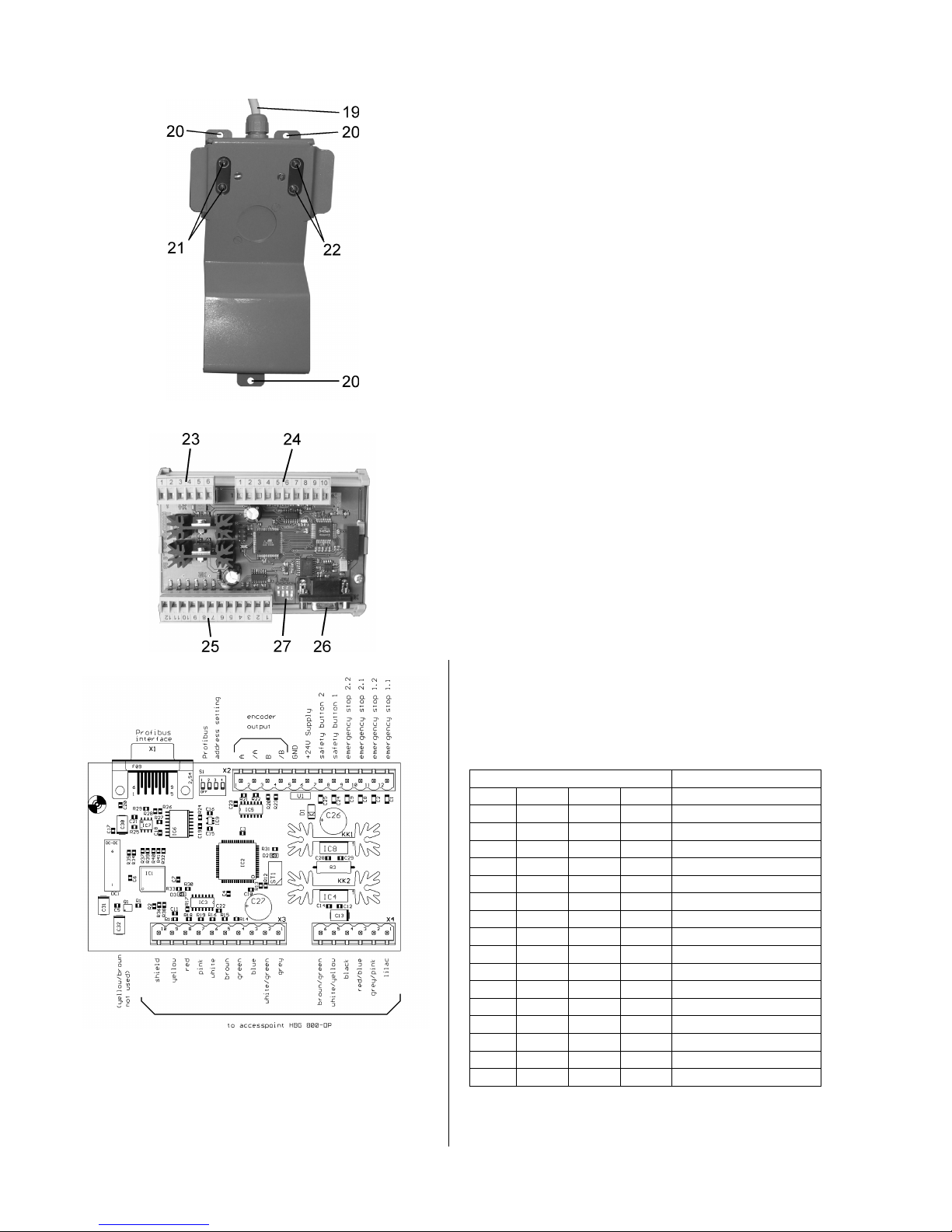
6.3 Charging station
19 connecting cable with plug
20 mounting holes Ø 5,5 mm
21 charging contacts
22 contacts for emergency stop
6.4 Connecting adaptor HBG 800-DP
23 X4 – connection to access point
24 X3 – connection to access point
25 X2 – connection to machine control
26 X1 – Profibus Interface
27 dip switch for Profibus address setting
The connecting adaptor HBG 800-DP is for
mounting on a DIN rail.
The scope of supply includes a connecting cable
with only one plug. It has to be connected to X3 and
X4 of the connecting adaptor. This cable is available
in 3 lengths: 3 m, 5 m, 10 m.
6.4.1 Address of Profibus
The address of the Profibus will be set by the dip
switch S1 (27). Changes will act after disconnecting
the adaptor from the power supply!
setting of S1 address
1 2 3 4
OFF OFF OFF OFF 2
ON OFF OFF OFF 3
OFF ON OFF OFF 4
ON ON OFF OFF 5
OFF OFF ON OFF 6
ON OFF ON OFF 7
OFF ON ON OFF 8
ON ON ON OFF 9
OFF OFF OFF ON 10
ON OFF OFF ON 11
OFF ON OFF ON 12
ON ON OFF ON 13
OFF OFF ON ON 14
ON OFF ON ON 15
OFF ON ON ON 16
ON ON ON ON 17

Operating manual HBG 800-DP Rev. 05 - 08/18 Hubitron Steuerungstechnik
Hubitron Steuerungstechnik, Hauptstr. 4/1, D-89611 Obermarchtal, Germany, Tel. +49(0)7375/922066, FAX +49(0)7375/922077 5 of 16
6.4.2 Pin assignment
Cable to access point
PIN color of wire function
X3.1 grey GND
X3.2 white/green +24 V
X3.3 blue +12 V
X3.4 green serial 1 out
X3.5 brown serial 1 ctrl
X3.6 white serial 1 in
X3.7 pink serial 2 in
X3.8 red serial 2 out
X3.9 yellow output 1
X3.10 shield grounding
X4.1 lilac emergency stop 1.1
X4.2 grey/pink emergency stop 1.2
X4.3 red/blue emergency stop 2.1
X4.4 black emergency stop 2.2
X4.5 white/yellow safety button 1
X4.6 brown/green safety button 2
Machine side
PIN description direction power
X2.1 Encoder A out 5V/20mA
X2.2 Encoder /A out 5V/20mA
X2.3 Encoder B out 5V/20mA
X2.4 Encoder /B out 5V/20mA
X2.5 GND -
X2.6 +24V supply in 0,5 A
X2.7 safety button 2 out 24V/2 A
X2.8 safety button 1 out 24V/2 A
X2.9 emergency stop 2.2 - 3 A
X2.10 emergency stop 2.1 - 3 A
X2.11 emergency stop 1.2 - 3 A
X2.12 emergency stop 1.1 - 3 A
X1 Profibus interface 9 pole D-SUB
7. Installation
Machine must be turned off before installation!
o Mount the charging station onto the 3 mounting
holes (20) on a suitable location with easy
access. The cable must be on top. Do not bend
the loading station!
o Install the access point on the machine control
panel near to the hand wheel interface,
preferably above the control panel. Underneath
the 2 covers (15) are 2 mounting holes each for
M5 screws (hole distance: 102 x 202 mm). The
connector for the anenna (14) must be on top.
o Install the charging station onto the access point
(X2, 18).
o Screw the short antenna into the antenna socket
(X3, 14).
o Connect the cable supplied with the access point
(X1, 17) and the connecting adaptor
o remove Sticker ("remove before use") with
magnet from the hand terminal.
Mounting positions:
enlosed in synthetic
enlosed in metal
Attention!
If machines have only one emergency stop channel,
both emergency stop contacts of the HBG 800-DP
must be connected in series!
7.1 Profibus installation
1. read the GSE file into the control unit.
Afterwords a new Profibus device with the name
HBG800-DP should be available. It includes the
following modules:
No Name length values
1 Poti Spindle 1 Byte 0 - 31
2 Poti Feed 1 Byte 0 – 31
3 Buttons 1-16 2 Byte (DW) 0 - 65535
4 Encoder 2 Byte (DW) ± 32768
5 Status 1 Byte 0 - 255
6 LED’s 1-12 2 Byte (DW) 0 – 65535
7 Text line 1 12 Byte Array ASCII
8 Text line 2 12 Byte Array ASCII
If the modules are not available you have to add it
manually.
Attention should be paid to:
1. all modules must be added
2. keep the order of the modules like in the table
above
A detailed description of the modules is
available in the appendix of this manual!
 Loading...