

Huber Unichiller 007 OLÉ, Unichiller 015 OLÉ, Unichiller 025 OLÉ, Unichiller 012 OLÉ, Unichiller 010 OLÉ Instruction Manual
Page 1
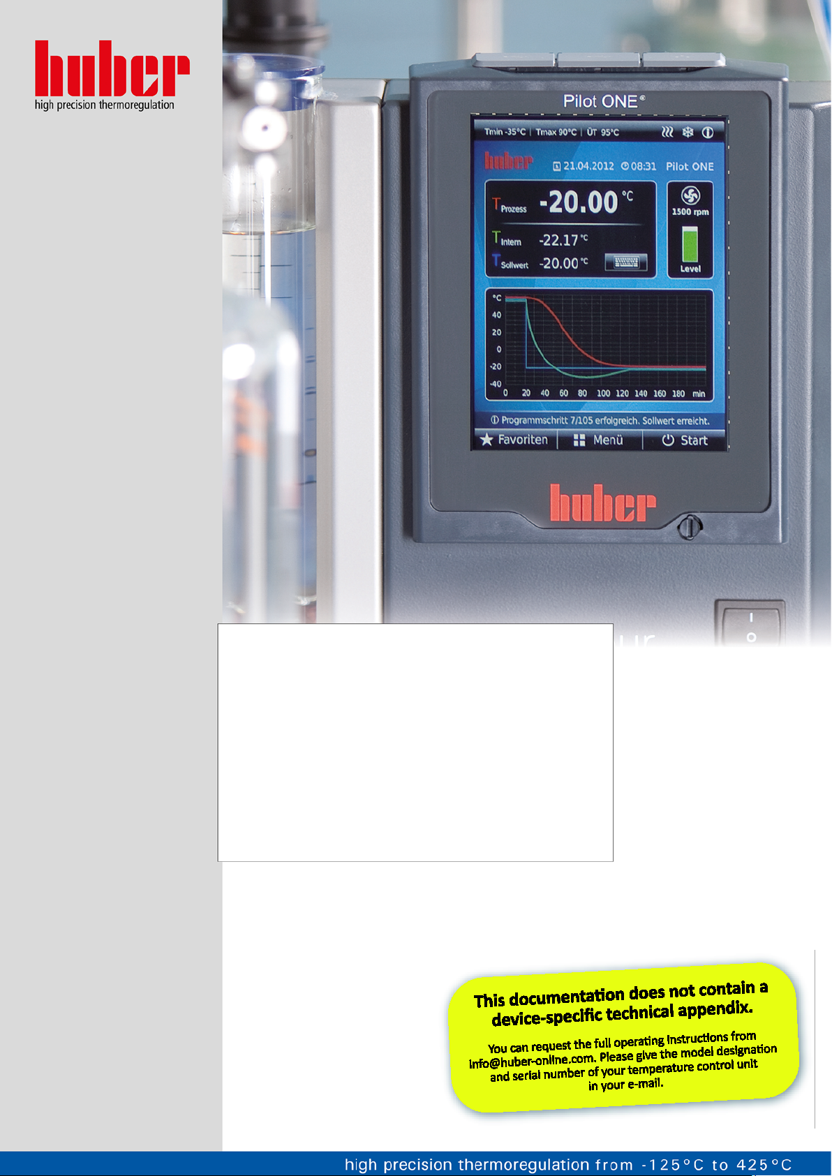
Minichiller® OLÉ
Unichiller® OLÉ
Operation Manual
V1.2.0
Page 2

Page 3

Minichiller® OLÉ
OPERATION MANUAL
Unichiller® OLÉ
V1.2.0
Page 4

Page 5

OPERATION MANUAL
5
Unichiller®
TABLE-TOP MODELS
Minichiller® 280 OLÉ
Minichiller® 300 OLÉ
Minichiller® 600 OLÉ
Minichiller® 900 OLÉ
Unichiller® 007 OLÉ
Unichiller® 01x OLÉ
Unichiller® 02x OLÉ
Minichiller®
OLÉ
This operation manual is a translation of the original operation manual.
Also for models with heater.
VALID FOR:
Abbreviations used in model names:
Without = with air cooling, P = stronger Pump, w = with water cooler, -H = with heater,
V1.2.0en/12.01.18//1.0.0 Minichiller® OLÉ, Unichiller® OLÉ
plus = with RS232 Interface
Page 6
OPERATION MANUAL
6
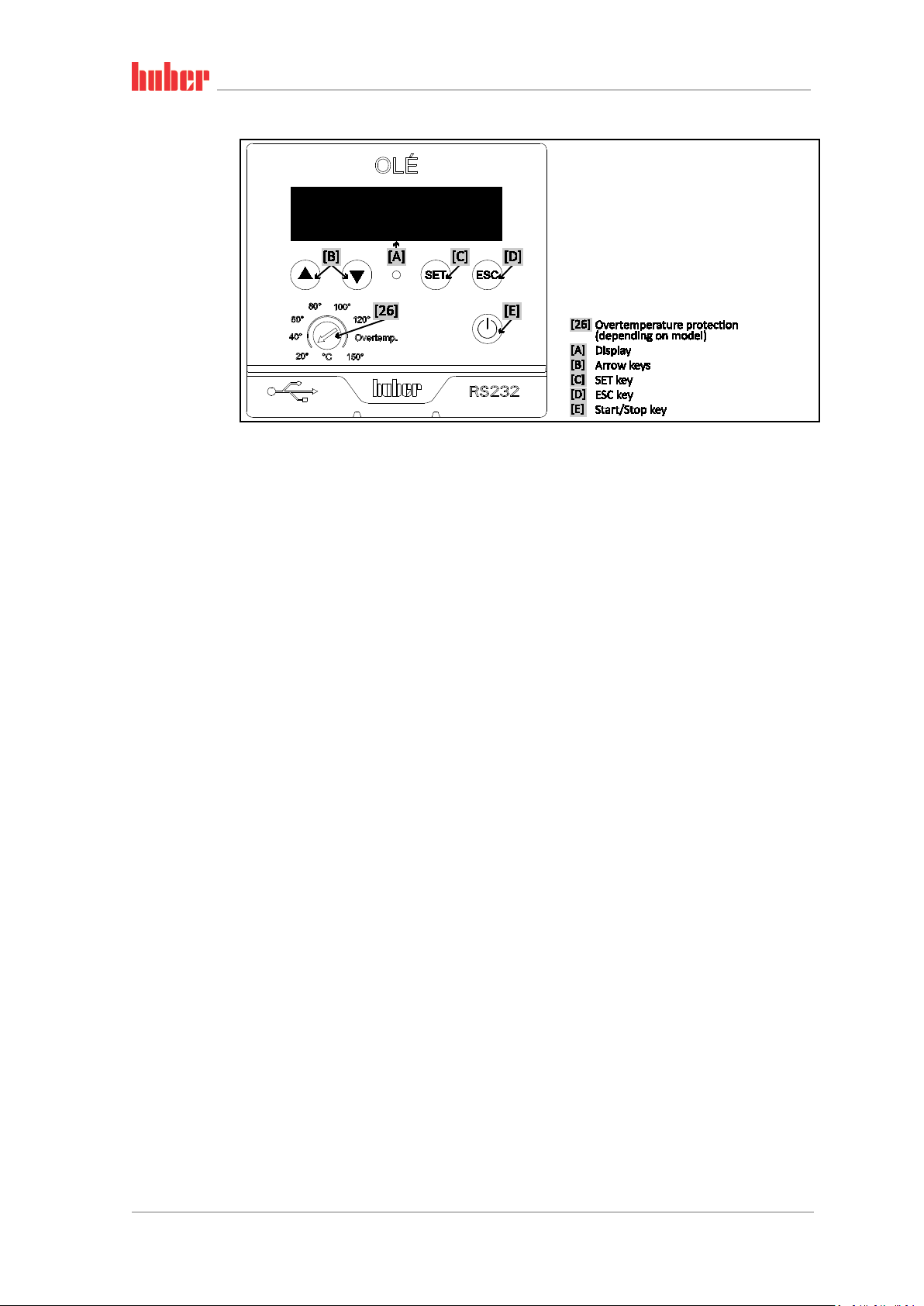
The control panel:
Displays and keys
Minichiller® OLÉ, Unichiller® OLÉ V1.2.0en/12.01.18//1.0.0
Page 7

7
OPERATION MANUAL
Table of contents
V1.2.0en/12.01.18//1.0.0
1 Introduction 12
1.1 Details on the declaration of conformity ....................................................... 12
1.2 Safety .......................................................................................................... 12
1.2.1 Symbols used for Safety Instructions .............................................................. 12
1.2.2 Proper operation ............................................................................................. 13
1.2.3 Reasonably foreseeable misuse ...................................................................... 13
1.3 Responsible bodies and operators – Obligations and requirements............... 14
1.3.1 Obligations of the responsible body ............................................................... 14
1.3.1.1 Proper disposal of resources and consumables ......................................... 14
1.3.1.2 Temperature control unit with natural refrigerants (NR) .......................... 15
1.3.1.3 Temperature control units with fluorinated greenhouse gases/refrigerants17
1.3.2 Requirements for operators ........................................................................... 17
1.3.3 Obligations of the operators ........................................................................... 17
1.4 General information ..................................................................................... 17
1.4.1 Description of workstation ............................................................................. 17
1.4.2 Safety devices to DIN 12876 ........................................................................... 18
1.4.2.1 Mechanical overtemperature protection ................................................... 18
1.4.2.2 Low level protection ................................................................................... 18
1.4.3 Further protective devices .............................................................................. 19
1.4.3.1 Power interruption ..................................................................................... 19
1.5 Exemplary illustrations of the cooling variants .............................................. 19
1.5.1 Air cooling ....................................................................................................... 19
1.5.2 Water cooling .................................................................................................. 20
1.5.3 Consequence of inadequate energy dissipation ............................................. 20
2 Commissioning 21
2.1 In-plant transport ......................................................................................... 21
2.1.1 Lifting and transporting the temperature control unit ................................... 21
2.1.1.1 Temperature control unit with lifting eyes ................................................ 21
2.1.1.2 Temperature control unit without lifting eyes ........................................... 22
2.1.2 Positioning the temperature control unit ....................................................... 22
2.1.2.1 Temperature control unit with casters ...................................................... 22
2.1.2.2 Temperature control unit without casters ................................................. 22
2.2 Unpacking .................................................................................................... 22
2.3 Ambient conditions ...................................................................................... 23
2.3.1 EMC-specific notes .......................................................................................... 24
2.4 Installation conditions .................................................................................. 24
2.5 Recommended temperature control and cooling water hoses ...................... 25
2.6 Wrench sizes and torques ............................................................................. 25
2.7 Temperature control units with water cooling .............................................. 25
2.8 Preparations for operation ........................................................................... 27
2.8.1 Unscrewing/activating the leveling feet (if any) ............................................. 27
2.8.2 Opening/closing the bypass valve ................................................................... 27
2.8.3 Enable / Disable silent operation (optional) ................................................... 28
2.9 Connecting externally closed application ...................................................... 28
2.9.1 Connecting an externally closed application .................................................. 28
2.10 Connecting to the power supply ................................................................... 29
V1.2.0en/12.01.18//1.0.0 Minichiller® OLÉ, Unichiller® OLÉ
Page 8

OPERATION MANUAL
8
2.10.1 Connection using socket with protective earth (PE) ....................................... 29
2.10.2 Connection via hard wiring ............................................................................. 30
3 Function description 31
3.1 Function description of the temperature control unit ................................... 31
3.1.1 General functions ............................................................................................ 31
3.1.2 Other functions ............................................................................................... 31
3.2 Information on the thermal fluids ................................................................ 31
3.3 To be noted when planning the test ............................................................. 32
3.4 Display and control instruments ................................................................... 33
3.4.1 Display ............................................................................................................. 33
3.4.2 Control instruments ........................................................................................ 34
3.4.2.1 Arrow keys .................................................................................................. 34
3.4.2.2 SET key ........................................................................................................ 34
3.4.2.3 ESC key ....................................................................................................... 35
3.4.2.4 Start/Stop key ............................................................................................. 35
3.4.3 Adjusting settings ............................................................................................ 35
3.5 Menu function ............................................................................................. 36
3.6 Functional examples .................................................................................... 37
3.6.1 Selecting a language ....................................................................................... 37
3.6.2 Setting the setpoint ........................................................................................ 37
3.6.3 Changing the Auto-Start function ................................................................... 37
4 Setup mode 38
4.1 Setup mode ................................................................................................. 38
4.1.1 Turning on the temperature control unit ....................................................... 38
4.1.2 Setting the overtemperature (OT) protection ................................................ 38
4.1.2.1 General information on the overtemperature protection ......................... 38
4.1.2.2 Setting the overtemperature protection .................................................... 39
4.1.3 Testing the overtemperature protection for functionality ............................. 39
4.2 Filling, venting, degassing and draining ......................................................... 40
4.2.1 Filling and venting externally closed application ............................................ 40
4.2.1.1 Filling and venting with >Sight glass< [23] ................................................. 41
4.2.1.2 Filling and venting with >Level indicator and drain< [38] .......................... 42
4.2.2 Draining externally closed applications .......................................................... 43
4.2.2.1 Draining with >Sight glass< [23] ................................................................. 43
4.2.2.2 Draining with >Level indicator and drain< [38] .......................................... 44
5 Normal operation 45
5.1 Automatic operation .................................................................................... 45
5.1.1 Temperature control ....................................................................................... 45
5.1.1.1 Starting the temperature control process .................................................. 45
5.1.1.2 Ending the temperature control process ................................................... 45
6 Interfaces and data communication 46
6.1 Controller interfaces .................................................................................... 46
6.1.1 USB-2.0 interface ............................................................................................ 46
6.1.1.1 USB-2.0 interface, device ........................................................................... 46
6.1.2 RS232 jack ....................................................................................................... 46
6.2 Interfaces on the temperature control unit (optional) ................................... 46
6.2.1 RS232 jack ....................................................................................................... 47
6.2.2 Connection jack for Pt100 process display sensor .......................................... 47
6.2.3 Jack ECS (External Control Signal) standby ..................................................... 47
Minichiller® OLÉ, Unichiller® OLÉ V1.2.0en/12.01.18//1.0.0
Page 9

9
OPERATION MANUAL
6.2.4 Connector POKO (floating contact) alarm ...................................................... 48
6.3 Data communication .................................................................................... 48
6.3.1 LAI commands ................................................................................................. 49
6.3.1.1 Command “V” (Verify) ................................................................................ 49
6.3.1.2 Command “L” (Limit) .................................................................................. 50
6.3.1.3 Command “G” (General) ............................................................................ 50
6.3.2 PP commands .................................................................................................. 52
7 Service/maintenance 53
7.1 Displays in the event of faults ....................................................................... 53
7.2 Maintenance ................................................................................................ 54
7.2.1 Function check and visual inspection ............................................................. 54
7.2.2 Replacing temperature control or coolant hoses ........................................... 55
7.2.2.1 Replacing temperature control hoses ........................................................ 55
7.2.2.2 Replacing coolant hoses ............................................................................. 55
7.2.3 Clean liquefier fins (air-cooled temperature control unit) ............................. 56
7.2.4 Clean hat-type strainer (dirt trap) (water-cooled temperature control unit) . 57
7.3 Thermal fluid inspection, replacement and circuit cleaning ........................... 57
7.3.1 Thermal fluid replacement ............................................................................. 58
7.3.1.1 Externally closed application ...................................................................... 58
7.3.2 Rinsing the thermal fluid circuit ...................................................................... 58
7.3.2.1 Rinsing a thermofluid circuit with >Sight glass< [23] ................................. 58
7.3.2.2 Rinsing the thermofluid circuit with >Level indicator and drain< [38] ....... 59
7.4 Cleaning the surfaces ................................................................................... 60
7.5 Inspect the mechanical seal .......................................................................... 60
7.6 Plug contacts ................................................................................................ 61
7.7 Decontamination/repairs ............................................................................. 61
8 Shutting down 62
8.1 Safety instructions and basic principles ........................................................ 62
8.2 Switch-off .................................................................................................... 62
8.3 Draining the cooling water ........................................................................... 63
8.3.1 Draining process ............................................................................................. 63
8.4 Packing ........................................................................................................ 63
8.5 Shipping ....................................................................................................... 63
8.6 Disposal ....................................................................................................... 64
8.7 Phone number and company address ........................................................... 65
8.7.1 Telephone number: Customer Support .......................................................... 65
8.7.2 Telephone number: Sales ............................................................................... 65
8.7.3 Email address: Customer Support ................................................................... 65
8.7.4 Service/return address .................................................................................... 65
8.8 Certificate of Compliance ............................................................................. 65
9 Annex 66
V1.2.0en/12.01.18//1.0.0 Minichiller® OLÉ, Unichiller® OLÉ
Page 10

OPERATION MANUAL
10
Minichiller® OLÉ, Unichiller® OLÉ V1.2.0en/12.01.18//1.0.0
Page 11

OPERATION MANUAL
11
Foreword
Dear Customer,
Thank you for choosing a temperature control unit from Peter Huber Kältemaschinenbau AG. You
have made a good choice. Thank you for your trust.
Please read the operation manual carefully before putting the unit into operation. Strictly follow all
notes and safety instructions.
Follow the operation manual with regard to transport, start-up, operation, maintenance, repair,
storage and disposal of the temperature control unit.
We fully warrant the temperature control unit for the specified normal operation.
The models listed on page 5 are referred to in this operation manual as temperature control units
and Peter Huber Kältemaschinenbau AG as Huber company or Huber.
Liability for errors and misprints excluded.
The following trademarks and the Huber logo are registered trademarks of Peter Huber Kältemaschinenbau AG
in Germany and/or other countries worldwide: BFT®, CC®, CC-Pilot®, Com.G@te®, Compatible Control®,
CoolNet®, DC®, E-grade®, Grande Fleur®, KISS®, Minichiller®, Ministat®, MP®, MPC®, Peter Huber Minichiller®,
Petite Fleur®, Pilot ONE®, RotaCool®, Rotostat®, SpyControl®, SpyLight®, Tango®, TC®, UC®, Unical®, Unichiller®,
Unipump®, Unistat®, Unistat-Pilot®, Unistat Tango®, Variostat®, Web.G@te®. The following trademarks are
registered in Germany to DWS Synthesetechnik: DW-Therm®, DW-Therm HT®
V1.2.0en/12.01.18//1.0.0 Minichiller® OLÉ, Unichiller® OLÉ
Page 12
Introduction
12
OPERATION MANUAL Chapter 1
1 Introduction
1.1 Details on the declaration of conformity
The equipment complies with the basic health and safety requirements of the European Directives
listed below:
▪ Machinery Directive 2006/42/EC
▪ Low Voltage Directive 2006/95/EC
▪ EMC Directive 2004/108/EC
1.2 Safety
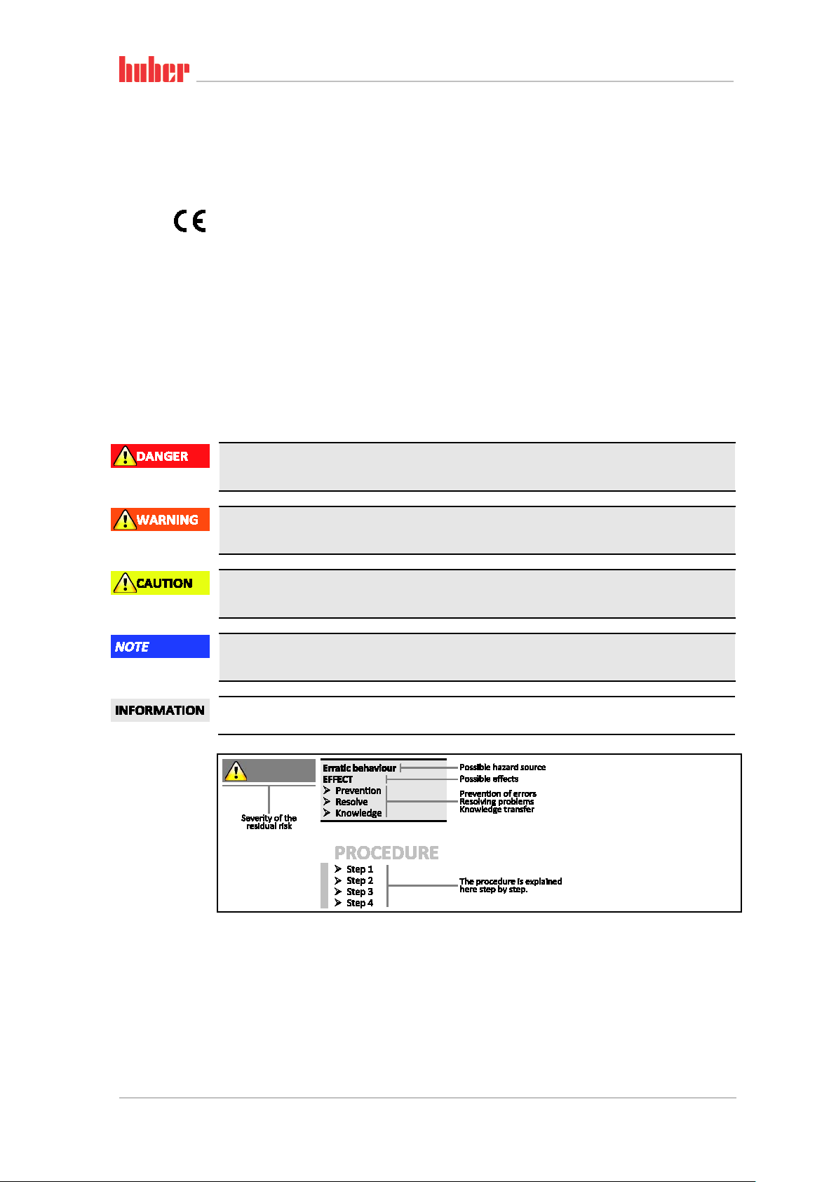
1.2.1 Symbols used for Safety Instructions
Safety instructions are marked by the below combinations of pictograms and signal words. The
signal word describes the classification of the residual risk when disregarding the operation manual.
Denotes an immediate hazardous situation that will result in death or serious injuries.
Safety information and
procedure
Denotes a general hazardous situation that may result in death or serious injuries.
Denotes a hazardous situation that can result in injury.
Denotes a situation that can result in property material damage.
Denotes important notes and usable hints.
The safety information in this operation manual is designed to protect the responsible body, operator and the equipment from damage. Safety information must always appear BEFORE instructions
and at the beginning of each chapter. You should be first informed about the residual risks due to
misuse before you begin an operation.
Minichiller® OLÉ, Unichiller® OLÉ V1.2.0en/12.01.18//1.0.0
Page 13

Introduction
13
Do NOT install or start up the temperature control unit within an ATEX zone.
ages!
Do not ignore, bypass, dismantle or disconnect any safety devices!
Chapter 1 OPERATION MANUAL
1.2.2 Proper operation
Operating the temperature control unit in a potentially explosive area
DEATH THROUGH EXPLOSION
Improper use
SERIOUS INJURY AND PROPERTY DAMAGE
Store the operation manual where it is easy to access in close proximity to the temperature
control unit.
Only adequately qualified operators may work with the temperature control unit.
Operators must be trained before handling the temperature control unit.
Check that the operators have read and understood the operation manual.
Define precise responsibilities of the operators.
Personal protective equipment must be provided to the operators.
Be sure to follow the responsible body’s safety rules to protect life and limb and to limit dam-
Modifications to the temperature control unit by third-parties
DAMAGE TO THE TEMPERATURE CONTROL UNIT
Do not allow third parties to make technical modifications to the temperature control unit.
In case of any modification of the temperature control unit not approved by the manufacturer,
the CE declaration of conformity becomes invalid.
Only specialists trained by the manufacturer may carry out modifications, repairs or mainte-
nance work.
The following must be observed without fail:
Only use the temperature control unit in a fault-free condition!
Have start-up and repairs carried out only by specialists!
The temperature control unit must not be used for any purposes other than temperature control in
accordance with the operation manual.
The temperature control unit is manufactured for industrial use. The temperature control unit maintains the temperature of certain applications, including glass or metal reactors or other expedient
items in laboratories and industry. Flow-through coolers and calibration baths must be used only in
combination with Huber temperature control units. Thermal fluids suitable for the overall system
are used. The chilling and heating capacity is provisioned at the pump connections or - where present - in the tempering bath. The technical specification of the temperature control unit is given in
the data sheet (from page 66 in section »Annex«). The temperature control unit must be installed,
configured and operated according to the handling instructions in this operating manual. Failure to
comply with the operation manual is deemed improper use. The temperature control unit conforms
to state-of-the-art technology and the recognized safety regulations. Safety devices are built into
your temperature control unit.
1.2.3 Reasonably foreseeable misuse
Use with medical devices (e.g. in Vitro diagnostic procedure) or for direct foodstuff temperature
control is NOT permissible.
The temperature control unit must NOT be used for any purposes other than temperature control in
accordance with the operation manual.
The manufacturer accepts NO liability for damage caused by technical modifications to the temper-
ature control unit, improper handling or use of the temperature control unit if the operation manual is not observed.
V1.2.0en/12.01.18//1.0.0 Minichiller® OLÉ, Unichiller® OLÉ
Page 14
Introduction
14
OPERATION MANUAL Chapter 1
1.3 Responsible bodies and operators – Obligations and
requirements
1.3.1 Obligations of the responsible body
The operation manual is to be stored where it is easy to access in close proximity to the temperature
control unit. Only adequately qualified operators (e.g. chemists, CTA, physicists etc.) are permitted
to work with the temperature control unit. Operators must be trained before handling the temperature control unit. Check that the operators have read and understood the operation manual. Define
precise responsibilities of the operators. Personal protective equipment must be provided to the
operators.
▪ The responsible body must install a condensation water / thermofluid drip tray below the tem-
perature control unit.
▪ The responsible body must check whether national regulations require the mandatory installation
of a drain tray for the installation area of the temperature control unit/the entire system.
▪ Our temperature control unit complies with all applicable safety standards.
▪ Your system, which uses our temperature control unit, must be as safe.
▪ The responsible body must design the system so as to ensure it is safe.
▪ Huber is not responsible for the safety of your system. The responsible body is responsible for the
safety of the system.
▪ Whilst the temperature control unit provided by Huber meets all the applicable safety standards,
integration into a system may give rise to hazards that are characteristic of the other system’s design and beyond the control of Huber.
▪ It is the responsibility of the system integrator to ensure that the overall system, into which this
temperature control unit is integrated, is safe.
▪ The >Mains isolator< [36] (if present) may be provided with a facility to lock the main isolator in
the off position to facilitate safe system installation and maintenance of the temperature control
unit. It is the responsibility of the responsible body to develop any lock-out/tag-out procedure in
accordance with local regulations (e.g. CFR 1910.147 for the US).
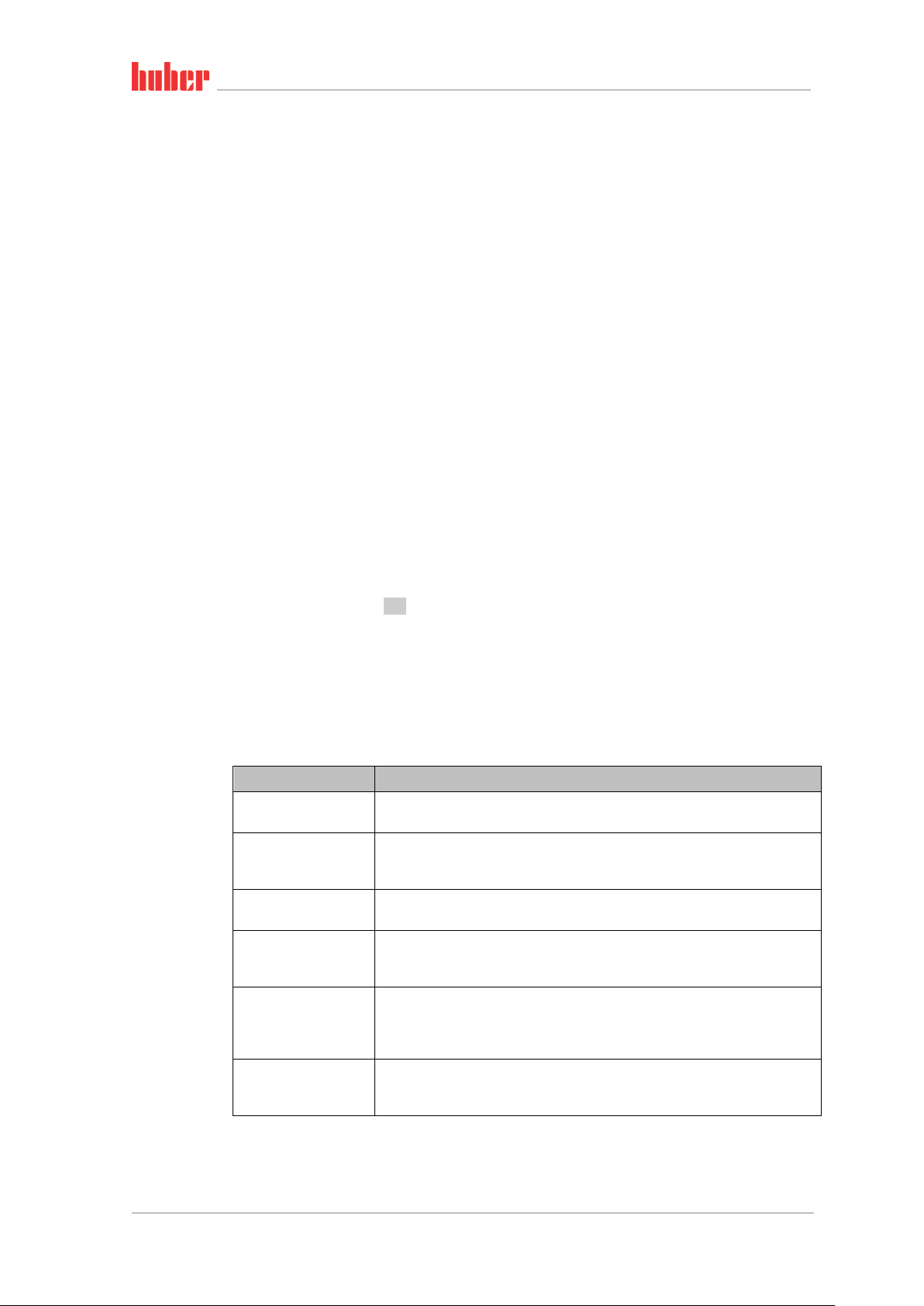
1.3.1.1 Proper disposal of resources and consumables
Do comply with all national disposal regulations applicable for you. Contact your local waste management company for any questions concerning disposal.
Overview
Material / Aids Disposal / Cleaning
Temperature control
unit packaging material
Thermal fluid
Filling accessories, e.g.
beaker
Aids such as towels,
cleaning cloths
Cleaning agents such as
stainless steel cleaning
agents, sensitive-fabrics
detergents
Consumables such as air
filter mats, temperature
control hoses
Keep the packaging material for future use (e.g. transport).
Please refer to the safety data sheet of the thermal fluid used for information on its
proper disposal.
Use the original thermal fluid container when disposing it.
Clean the filling accessories for reuse. Make sure that the materials and cleaning
agents used are properly disposed of.
Tools used to take up spilled thermal fluid must be disposed of in the same fashion
as the thermal fluid itself.
Tools used for cleaning must be disposed of depending on the cleaning agent used.
Please refer to the safety data sheet of the cleaning agent used for information on its
proper disposal.
Use the original containers when disposing of large quantities of cleaning agents.
Please refer to the safety data sheet of the consumables used for information on
their proper disposal.
Minichiller® OLÉ, Unichiller® OLÉ V1.2.0en/12.01.18//1.0.0
Page 15
Introduction
15
The temperature control unit is not approved for operation in an ATEX zone.
Chapter 1 OPERATION MANUAL
1.3.1.2 Temperature control unit with natural refrigerants (NR)
Over 8 g refrigerant per m³ room air
DEATH OR SERIOUS INJURY DUE TO EXPLOSION
Observe the rating plate (amount of natural refrigerant contained) and the room size (maxi-
mum room concentration of natural refrigerant in case of leakage) when installing the temperature control unit.
Over 8 g refrigerant per m³ room air: A gas warning sensor must be fitted and functioning.
The gas warning sensor must be calibrated and maintained at regular intervals (between 6 and
12 months).
Huber products with natural refrigerants work with numerous proven, safe and highly-sustainable
technologies. The relevant standards and regulations for temperature control units with natural
refrigerants contain a number of stipulations, the importance of complying with which is set out
below. Also observe on page 13 the section »Proper operation«.
Huber temperature control units are constructed to be permanently sealed and are carefully
checked for leak tightness. Temperature control units with more than 150 g natural refrigerant are
equipped with an additional gas warning sensor. To find out whether your temperature control unit
is equipped with a gas warning sensor, refer to the data sheet from page 66 in section »Annex«.
The fill quantity of your temperature control unit is stated on the data sheet (from page 66 in section »Annex«) or on the rating plate on the rear of the temperature control unit. Observe page 23,
section »Ambient conditions« and page 24, section »Installation conditions«.
Classifying the applica-
tion field
Class of
application
field
A General
B Monitored Laboratories 2.5 kg
C
Temperature control units with more than 1 kg refrigerant must not be installed below ground level (GL).
Application field
Access only for
authorized
persons
Example of the installation
location
Publicly accessible area in a
public building
Production equipment 10.0 kg
Max.
quantity of
refrigerant
3
8 g/m
ambient air
Max. permissible
quantity above
ground level (GL)
1.5 kg
AND
Temperature control units with up to 150 g natural refrigerant
▪ The temperature control unit has been constructed to the requirements of EU and EFTA coun-
tries.
▪ Use the table as guidance for classifying the application field. Respect the max. refrigerant quanti-
ty stated therein.
Temperature control units WITH pre-installed gas warning sensor and > 150 g natural refrigerant
▪ The temperature control unit has been constructed to the requirements of EU and EFTA coun-
tries.
▪ Use the table as guidance for classifying the application field. Respect the max. refrigerant quanti-
ty or the permissible highest quantity above ground level (GL) stated therein.
▪ Ventilation with optional supply and exhaust air connection: Use the temperature control unit’s
supply and exhaust air connection to connect it to the building’s exhaust system (see wiring diagram from page 66 in Section »Annex«). First, remove the cover to the air inlet connection; an air
filter mat is installed behind it. This air filter mat must be checked / replaced at regular intervals
so that the air flowing into the temperature control unit is not reduced (see page 54, Section
»Function check and visual inspection«). Connect the building’s exhaust system with the temperature control unit’s exhaust air port. The cover of the supply air port mustnot be removed if the
exhaust system provided in a building is not used.
V1.2.0en/12.01.18//1.0.0 Minichiller® OLÉ, Unichiller® OLÉ
Page 16

Introduction
16
The temperature control unit is not approved for operation in an ATEX zone.
OPERATION MANUAL Chapter 1
▪ The mounting plate for mounting a gas warning sensor is located inside the temperature control
unit in the vicinity of the >Cable entry gas warning sensor<[100].
▪ For the position of the >Cable entry gas warning sensor< [100], please refer to the wiring diagram
from page
▪ Additional information on the pre-installed gas detection sensor:
- The built-in gas detection sensor enables a safety shutdown at 20% of the lower explosive
- A 24 V DC external power supply must be available for the pre-installed gas warning sen-
- The responsible body is responsible for the calibration of the gas detection sensor prior to
Temperature control units WITHOUT pre-installed gas warning sensor and > 150 g natural refrigerant
Over 8 g refrigerant per m³ room air
DEATH OR SERIOUS INJURY DUE TO EXPLOSION
Observe the rating plate (amount of natural refrigerant contained) and the room size (maxi-
mum room concentration of natural refrigerant in case of leakage) when installing the temperature control unit.
Over 8 g refrigerant per m³ room air: A gas warning sensor must be fitted and functioning.
The gas warning sensor must be calibrated and maintained at regular intervals (between 6 and
12 months).
66 in Section »Annex«.
limit via a power disconnect relay that is to be installed by the responsible body. The
temperature control unit is thus switched off early and safely in case of fault.
sor. The alarm output of the gas warning sensor uses a 4 - 20 mA signal. Please refer to the
data sheet of the gas warning sensor for further technical information. A separate pro-
cessing unit is available as an accessory for the control of the power disconnect relay. The
processing unit provides a potential-free switching contact and simultaneously supplies
power to and analyzes the gas warning sensor. Both variants require the responsible body
to provide the necessary dimensioning and installation. Please refer to the data sheet of
the gas warning sensor for the technical installation information. The alarm of the gas detection system can be connected to the responsible body’s alarm control unit. The responsible body is responsible for this and other measures.
initial operation and the observance of calibration and maintenance intervals specified in
the operating manual. We recommend to set calibration and maintenance intervals between 6 and 12 months if no information is provided. For increased safety requirements,
shorter intervals can be specified. On request, we will recommend a specialist company to
carry out calibration and maintenance.
▪ The temperature control unit has been constructed to the requirements of EU and EFTA coun-
tries.
▪ Use the table as guidance for classifying the application field. Respect the max. refrigerant quanti-
ty or the permissible highest quantity above ground level (GL) stated therein.
▪ Ventilation with optional supply and exhaust air connection: Use the temperature control unit’s
supply and exhaust air connection to connect it to the building’s exhaust system (see wiring diagram from page 66 in Section »Annex«). First, remove the cover to the air inlet connection; an air
filter mat is installed behind it. This air filter mat must be checked / replaced at regular intervals
so that the air flowing into the temperature control unit is not reduced (see page 54, Section
»Function check and visual inspection«). Connect the building’s exhaust system with the temperature control unit’s exhaust air port. The cover of the supply air port mustnot be removed if the
exhaust system provided in a building is not used.
▪ NO gas warning sensor is installed in this temperature control unit! Make sure that the installa-
tion site of the temperature control unit is sufficiently protected in the event of malfunction.
These include:
- Installation of a gas warning sensor for the building (room monitoring).
- Permanent ventilation of the temperature control unit and/or the installation site.
- All-pole disconnection in the event of malfunction of the temperature control unit.
Minichiller® OLÉ, Unichiller® OLÉ V1.2.0en/12.01.18//1.0.0
Page 17

Introduction
17
Chapter 1 OPERATION MANUAL
1.3.1.3 Temperature control units with fluorinated greenhouse gases/refrigerants
F gases regulation (EC) No. 517/2014 of April 16, 2014, on fluorinated greenhouse gases, and re-
pealing Regulation (EC) No. 842/2006.
These regulations deal with all systems that contain fluorinated refrigerants. The substances dealt
with in Directive (EC) No. 1005/2009 of the European Parliament and of the Council of 16 September
2009 that deplete the ozone layer are excluded (CFC/HCFC).
The directive regulates the reduction of the emission, utilization, recovery, and destruction of certain fluorinated greenhouse gases. It also regulates the identification and disposal of products and
devices that contain these gases. Since July 4, 2007, responsible bodies must check their stationary
refrigeration systems for leaks at regular intervals, and have any leaks eliminated immediately.
Directive (EC) No. 303/2008 contains stipulations on the training and certification of companies and
personnel that are permitted to execute the specified activities.
Obligations of the responsible bodies:
▪ Directive (EC) No. 842/2006 already imposed a number of obligations upon responsible bodies
regarding certain fluorinated greenhouse gases. The new Ordinance on Fluorinated Greenhouse
Gases upholds these to a large extent. Some duties are added while others are designed differently by this new ordinance. Please refer to the text of this ordinance for a complete overview of the
individual responsibilities of responsible bodies.
▪ General obligation to reduce emissions.
▪ Only certified companies may maintain, repair or decommission refrigeration systems. The re-
sponsible bodies must verify that these companies are certified.
▪ Regular leak tests of stationary refrigeration systems by certified personnel (such as Huber service
engineers). The required test interval is based on the refrigerant filling capacity and the type of
refrigerant, converted to CO
▪ Responsibility of responsible bodies operating a plant to recover F-gases by certified personnel.
▪ Obligatory documentation requirement in the refrigeration system’s operation manual, specifying
type and volume of refrigerant used or recovered. The responsible body must keep the records
for at least 5 years after their creation and present it to the responsible authority upon request.
▪ Temperature control units with natural refrigerants (NR) are exempt from this Directive.
▪ Please refer to the data sheet or name plate of your temperature control unit for the quantity and
type of refrigerant.
▪ Additional information about the definition of the inspection interval can be found on our web-
site.
2 equivalent.
2
1.3.2 Requirements for operators
Work on the temperature control unit is reserved for appropriately qualified specialists, who have
been assigned and trained by the responsible body to do so. Operators must be at least 18 years old.
Under 18-year olds may operate the temperature control unit only under the supervision of a qualified specialist. The operator is responsible vis-a-vis third-parties in the work area.
1.3.3 Obligations of the operators
Carefully read the operation manual before operating the temperature control unit. Please observe
the safety instructions. When operating the temperature control unit, wear appropriate personal
protective equipment (e.g. safety goggles, protective gloves, non-slip shoes).
1.4 General information
1.4.1 Description of workstation
The workstation is located at the control panel in front of the temperature control unit. The workstation is determined by the customer's connected peripheries. Accordingly, it must be designed
safe by the responsible body. The workstation design also depends on the applicable requirements
of the German occupational health and safety regulations [BetrSichV] and the risk analysis for the
workstation.
V1.2.0en/12.01.18//1.0.0 Minichiller® OLÉ, Unichiller® OLÉ
Page 18
Introduction
18
OPERATION MANUAL Chapter 1
1.4.2 Safety devices to DIN 12876
The rating of your temperature control unit is stated on the data sheet in the appendix.
Rating of laboratory
thermostats and
laboratory baths
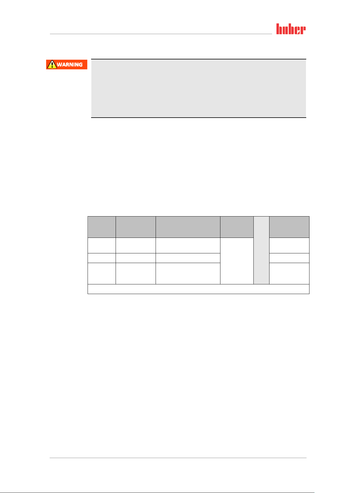
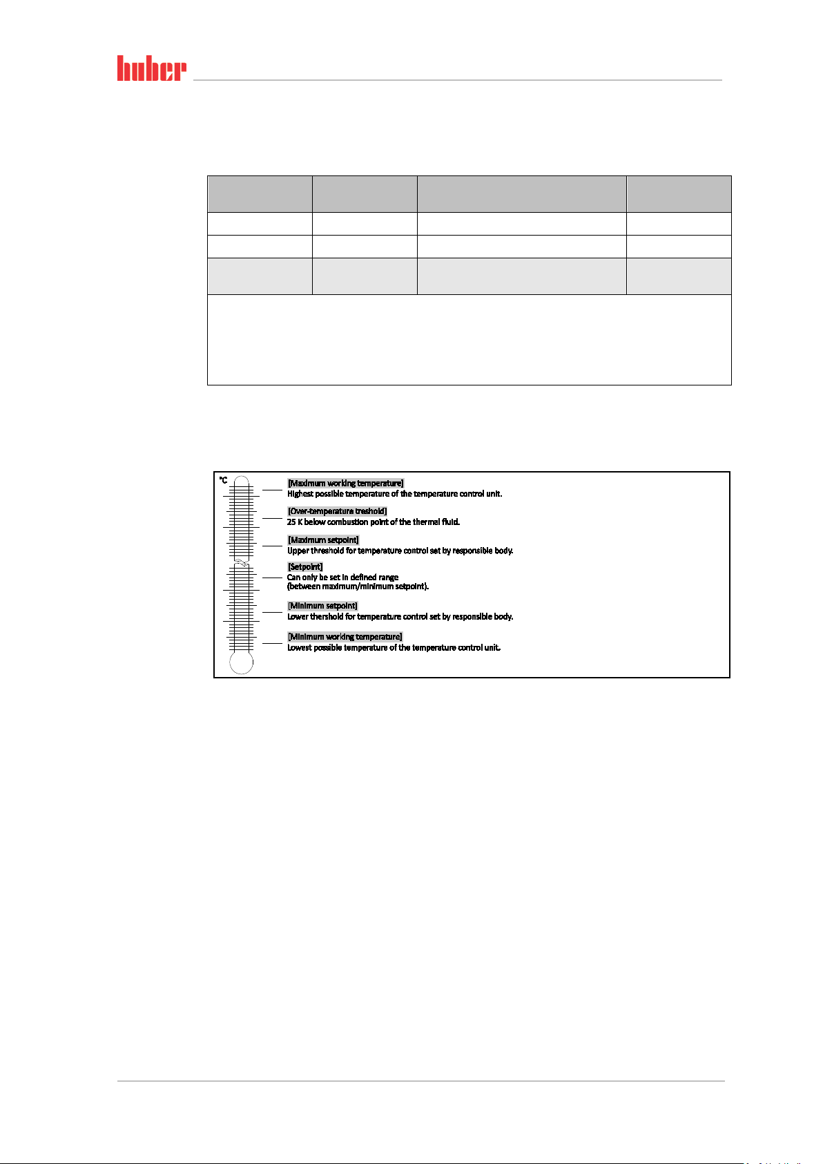
Overview of the tem-
perature thresholds
Classification
I Non-combustible a) Overheat protection c) NFL
II Combustible b) Adjustable overheat protection FL
III Combustible b)
a)
Usually water; other fluids only if non-combustible even within the temperature range of an individual fault.
b)
The temperature control media must have a combustion point of ≥ 65 °C.
c)
The overheat protection can, for instance, can be realized using a suitable fill level sensor or a suitable temper-
ature limiter.
d)
Optional at the choice of the manufacturer.
▪ Temperature control units with heating correspond to class number III/FL. These temperature
control units are characterized by an “H” in the device name.
▪ Temperature control units without heating correspond to class number I/NFL.
Temperature
control medium
Technical requirements Identification d)
Adjustable overtemperature protection
and additional low-level protection
FL
1.4.2.1 Mechanical overtemperature protection
Only temperature control units with a heater are fitted with a mechanical overtemperature protection. Set the overtemperature protection as described on page 38 in section »Setting the overtem-
perature (OT) protection«.
1.4.2.2 Low level protection
Minichiller with heater: A mechanical float is used for level monitoring. A floating body, which is
guided in a device, floats on the surface of the thermal fluid. Depending on the level of the thermal
fluid, the float device signals the electronics a state of good (in case of sufficient filling) or a state of
bad (in case of insufficient filling).The functionality of the float is checked at regular intervals during
continuous operation.
Unichiller with heater: The low level protection operates via a pressure sensor in the thermal fluid
circuit. The pump and the thermal fluid provide the required pressure at the pressure sensor. Air in
the system (fill level too low, inadequately vented) prevents the pressure from reaching the value
specified at the pressure sensor. Temperature control and circulation are interrupted.
Minichiller® OLÉ, Unichiller® OLÉ V1.2.0en/12.01.18//1.0.0
Page 19
Introduction
19
Chapter 1 OPERATION MANUAL
1.4.3 Further protective devices
Emergency strategy – isolate the power supply!
Disconnect the temperature control unit from the power supply!
1.4.3.1 Power interruption
Following a power outage (or when switching on the temperature control unit), this function can be
used to determine how the temperature control unit is supposed to respond.
Auto-Start function is turned off
The temperature control is started only by manual input when the temperature control unit is
turned on.
Auto-Start function is turned on
The temperature control unit is set to the same state it was in before the power outage. For example, before the power outage: Thermoregulation is off; after power outage: Thermoregulation is off.
If temperature control is active during a power outage, the process will automatically continue after
the power outage.
Further information can be found on page 37 in section »Changing the Auto-Start function«.
1.5 Exemplary illustrations of the cooling variants
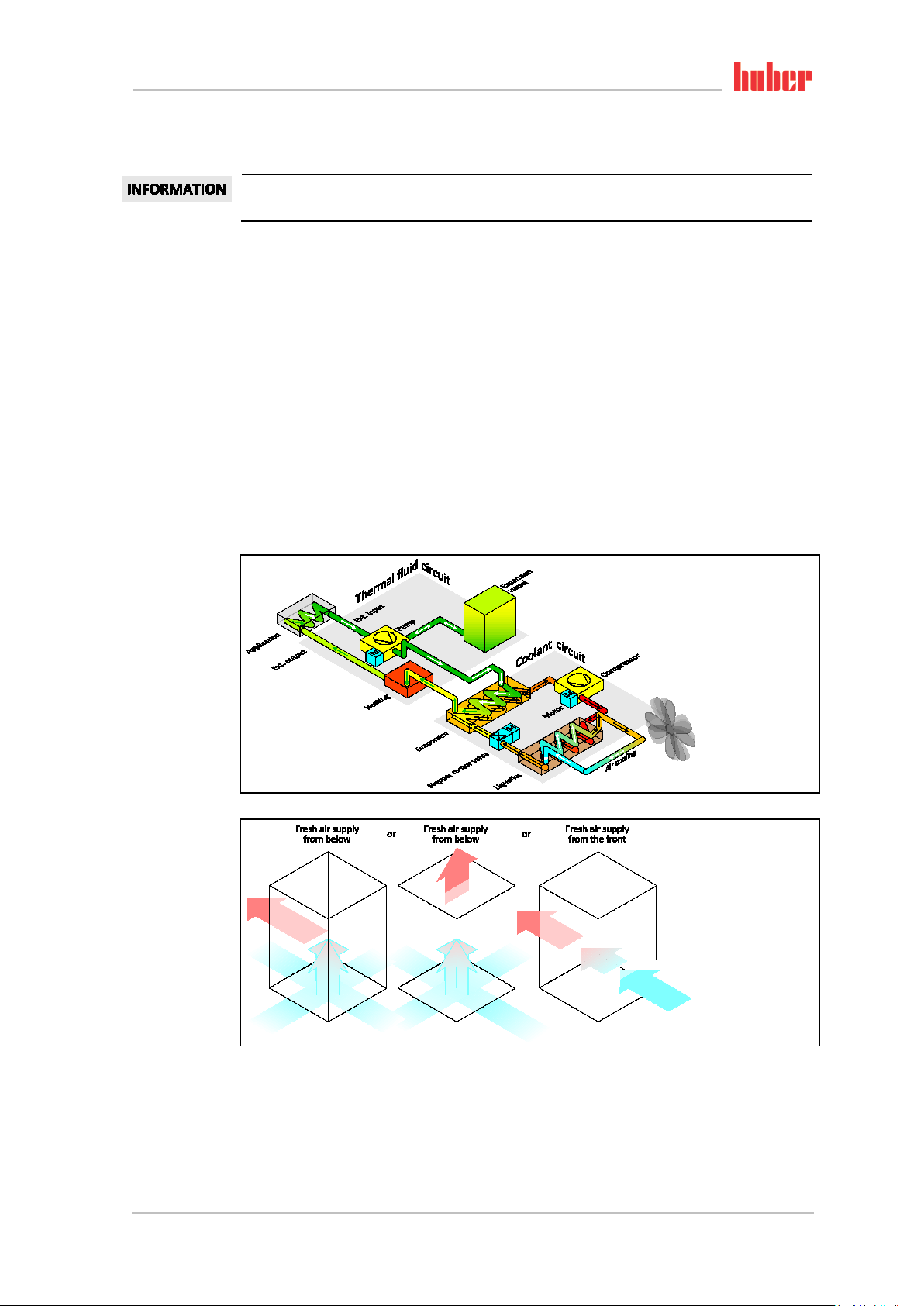
1.5.1 Air cooling
Example: Air cooling
Air inlet
V1.2.0en/12.01.18//1.0.0 Minichiller® OLÉ, Unichiller® OLÉ
Page 20
Introduction
20
OPERATION MANUAL Chapter 1
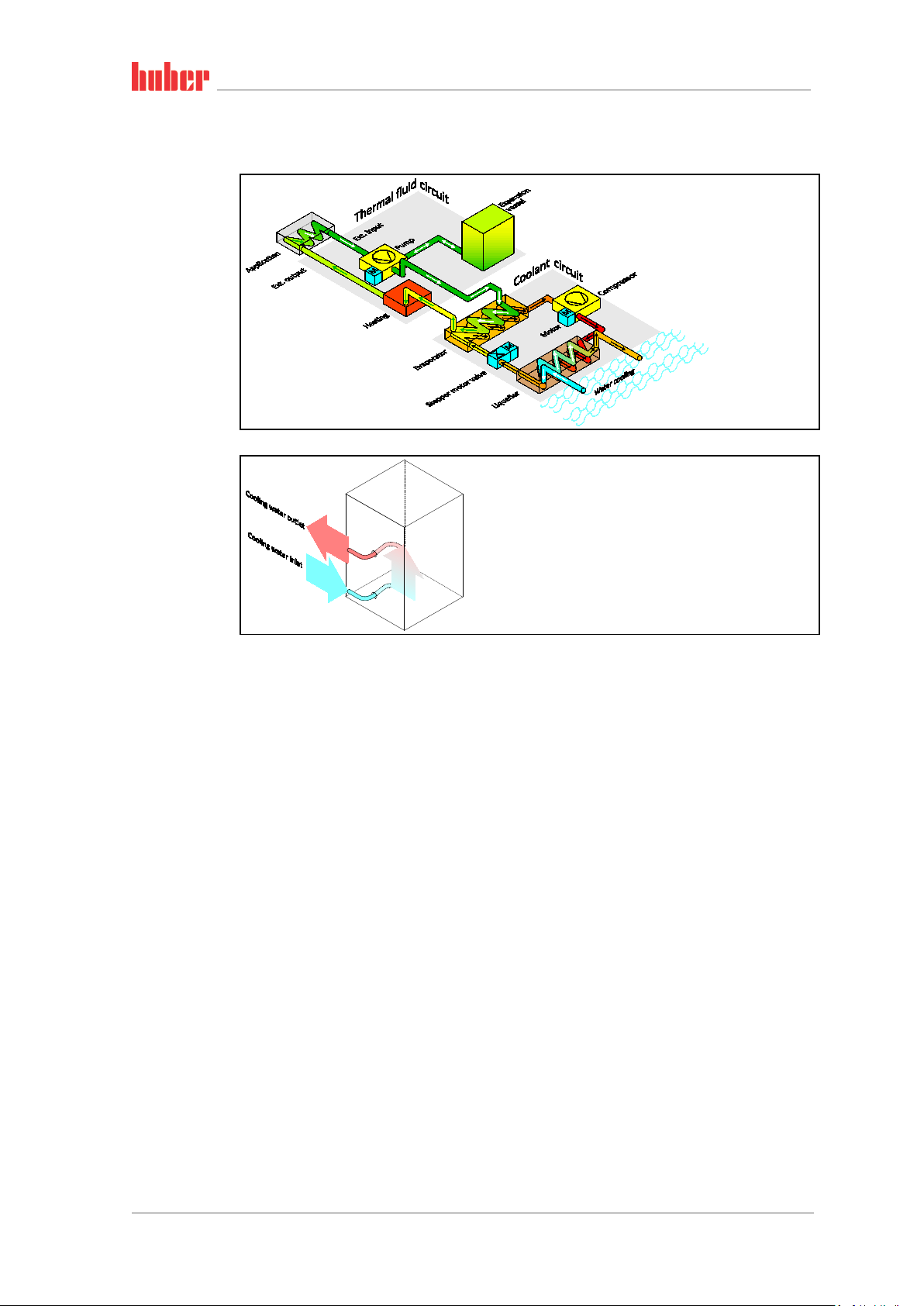
1.5.2 Water cooling
Example: Water cool-
ing
Water connection
1.5.3 Consequence of inadequate energy dissipation
Room air/cooling water
Consequences of, for instance, contamination of the liquefier fins, inadequate clearance between
temperature control unit to wall/bath wall, room air/cooling water too warm, cooling water differential pressure too low, suction strainer contamination: The refrigerant in the coolant circuit can no
longer fully discharge the admitted energy to the room air/cooling water. Thus there is not sufficient
liquefied refrigerant available, the condensation temperature and the energy consumption to rise.
Coolant circuit
Consequences of inadequate refrigerant quantity/rising condensation temperature: Not all the
cooling capacity from the coolant circuit is available at the evaporator. This means reduced energy
transmission from the thermal fluid circuit.
Thermal fluid circuit
Consequence of inadequate energy dissipation from the thermal fluid: The thermal fluid can only
dissipate the energy from your application to a limited extent.
Application
Consequences of inadequate energy dissipation from the application: The energy created (exothermic) in the application can no longer be fully dissipated.
Temperature control unit
An electronically-controlled expansion valve is used in the temperature control unit to optimize the
power adjustment. The expansion valve always provisions the maximum possible cooling capacity
within the permissible ambient temperature range. The temperature control unit switches off when
the upper range is reached (maximum permissible ambient temperature).
Minichiller® OLÉ, Unichiller® OLÉ V1.2.0en/12.01.18//1.0.0
Page 21

Commissioning
21
activated parking brake!
Only transport the temperature control unit in an upright position.
weight of the temperature control unit into account.
Chapter 2 OPERATION MANUAL
2 Commissioning
2.1 In-plant transport
Temperature control unit is not transported / moved according to the specifications in this operation manual
DEATH OR SERIOUS INJURY DUE TO CRUSHING
Always transport / move the temperature control unit according to the specifications in this
operation manual.
Wear personal protective equipment during transport.
Always work with the specified number of persons when moving the temperature control unit
on casters (if any).
If the temperature control unit is equipped with casters and parking brakes:
2 parking brakes are always freely accessible when moving the temperature control unit. Activate the 2 parking brakes in an emergency!
If only one parking brake is activated on the casters in an emergency:
The temperature control unit is not stopped but rotates around the axis of the caster with the
Temperature control unit transported in a horizontal position
DAMAGE TO THE COMPRESSOR
▪ If available, use the lugs on the top side of the temperature control unit for transportation.
▪ Use an industrial truck for transport.
▪ The casters on the temperature control unit are not suitable for transport. The casters are sym-
metrically loaded with 25% of the total mass of the temperature control unit.
▪ Remove the packing material (e.g. the palette) only at the place of installation.
▪ Protect the temperature control unit from transport damage.
▪ Do not transport the temperature control unit alone and without aids.
▪ Check the load bearing capacity of the transportation route and the place of installation.
▪ The parking brakes must be activated at the casters (if any) and/or the leveling feet (if any) must
be unscrewed/activated before the temperature control unit is put into operation (see page 27,
section »Unscrewing/activating the leveling feet (if any)«).
2.1.1 Lifting and transporting the temperature control unit
2.1.1.1 Temperature control unit with lifting eyes
The temperature control unit is raised at the lifting eyes without load handling attachments
DAMAGE TO THE TEMPERATURE CONTROL UNIT
Always use load handling attachments when lifting and transporting the temperature control
unit.
The lifting eyes are only designed for a load without inclination (0°).
The load handling attachment used must be adequately dimensioned. Take the dimensions and
▪ Do not lift and transport the temperature control unit at the lifting eyes alone and without aids.
▪ Lift and transport the temperature control unit at the lifting eyes only with a crane or an industrial
truck.
▪ The crane or industrial truck must have a lifting force equal to or greater than the weight of the
temperature control unit. See the data sheet (from page 66 in section »Annex«) for the weight of
the temperature control unit.
V1.2.0en/12.01.18//1.0.0 Minichiller® OLÉ, Unichiller® OLÉ
Page 22

Commissioning
22
»Phone number and company address«.
OPERATION MANUAL Chapter 2
2.1.1.2 Temperature control unit without lifting eyes
▪ Do not lift and transport the temperature control unit alone and without aids.
▪ Lift and transport the temperature control unit only with an industrial truck.
▪ The industrial truck must have a lifting force equal to or greater than the weight of the tempera-
ture control unit. See the data sheet (from page 66 in section »Annex«) for the weight of the
temperature control unit.
2.1.2 Positioning the temperature control unit
2.1.2.1 Temperature control unit with casters
▪ Do not use the casters for transportation to the place of installation. Observe page 21, section
»Lifting and transporting the temperature control unit« for the transport to the place of installa-
tion.
▪ Use the rollers only for positioning at the place of installation.
▪ Only ever move the temperature control unit on casters if the surface is level, without a gradient,
non-slip and stable.
▪ Do not move the temperature control unit alone.
▪ At least 2 persons are required to move the temperature control unit on casters. At least 5 per-
sons are required to move the temperature control unit on casters if the total weight of the temperature control unit is over 1.5 tons.
▪ The parking brakes must be activated at the casters and/or the leveling feet (if any) must be un-
screwed/activated before the temperature control unit is put into operation (see page 27, section
»Unscrewing/activating the leveling feet (if any)«).
2.1.2.2 Temperature control unit without casters
▪ An industrial truck must be used for positioning the temperature control unit.
▪ Do not move the temperature control unit alone.
▪ At least 2 persons are required to move the temperature control unit.
▪ The industrial truck must have a lifting force equal to or greater than the weight of the tempera-
ture control unit. See the data sheet (from page 66 in section »Annex«) for the weight of the
temperature control unit.
▪ The leveling feet (if any) must be unscrewed/activated before the temperature control unit is put
into operation (see page 27, section »Unscrewing/activating the leveling feet (if any)«).
2.2 Unpacking
Starting up a damaged temperature control unit
MORTAL DANGER FROM ELECTRIC SHOCK
Do not operate a damaged temperature control unit.
Please contact the Customer Support. The telephone number can be found on page 65, section
PROCEDURE
Check for damage to the packaging. Damage can indicate property damage to the temperature
control unit.
Check for any transport damage when unpacking the temperature control unit.
Always contact your forwarding agent regarding the settlement of claims.
Follow the instructions on page 14, section »Proper disposal of resources and consumables« for
the disposal of packaging material.
Minichiller® OLÉ, Unichiller® OLÉ V1.2.0en/12.01.18//1.0.0
Page 23

Commissioning
23
tions«.
Chapter 2 OPERATION MANUAL
2.3 Ambient conditions
Unsuitable ambient conditions/unsuitable installation
SERIOUS INJURY DUE TO CRUSHING
Comply with the requirements under sections »Ambient conditions« and »Installation condi-
Make sure there is adequate fresh air available at the site for the circulation pump and the compressors. The warm exhaust air must be able to escape upwards unhindered.
Free-standing model
For the connection data, see the data sheet (from page 66 in section »Annex«).
Use of the temperature control unit is permitted only under normal ambient conditions in accordance with DIN EN 61010-1:2011:
▪ Use only indoors. The illuminance must be at least 300 lx.
▪ Installation altitude up to 2000 meters above sea level .
▪ Maintain wall and ceiling clearance for adequate air exchange (dissipation of waste heat, supply
of fresh air for the temperature control unit and work area). Ensure adequate floor clearance for
air-cooled temperature control units. Do not operate this temperature control unit from within
the box or with an inadequately dimensioned bath. This inhibits the exchange of air.
▪ Ambient temperature values are provided on the technical data sheet; compliance with the ambi-
ent conditions is mandatory, to ensure trouble-free operation.
▪ Relative humidity up to 32 °C max. 80% and decreasing linearly to 50% up to 40 °C.
▪ Short distance to supply connections.
▪ The temperature control unit must not be installed so as to hinder or prevent access to the isola-
tor (to the power supply).
▪ Magnitude of the power supply fluctuations: see data sheet from page 66 in section »Annex«.
▪ Transient surges, as would normally occur in the power supply system
▪ Installation Class 3
▪ Applicable degree of soiling: 2.
▪ Surge category II.
Observe page 19 of section »Exemplary illustrations of the cooling variants«.
Wall clearance to
temperature control
unit
Clearance to the temperature control unit in cm
Air cooling
Water cooling
Side of the
temperature
control unit
[A1] Top Air outlet on top of unit: free standing –
[A2] Top can be located under a bench can be located under a bench
[B] Left min. 20 min. 10
[C] Right min. 20 min. 10
[D] Front min. 20 min. 10
[E] Rear min. 20 min. 20
V1.2.0en/12.01.18//1.0.0 Minichiller® OLÉ, Unichiller® OLÉ
Page 24

Commissioning
24
Do not put temperature control unit on power cable.
Activate brakes on the wheels.
OPERATION MANUAL Chapter 2
Clearance to the temperature control unit in cm (for operation in a bath)
Air cooling
Side of the
temperature
control unit
[A1] Top Air outlet on top of unit: free standing –
[A2] Top can be located under a bench can be located under a bench
[B] Left min. 20 min. 20
[C] Right min. 20 min. 20
[D] Front min. 20 min. 20
[E] Rear min. 20 min. 20
Water cooling
2.3.1 EMC-specific notes
These devices are suitable for the operation in “industrial electromagnetic environments”. It meets
the “immunity requirements” of the currently applicable EN61326-1, which are required for this
environment.
It also meets the “interference emission requirements” for this environment. It is a Group 1 and
Class A unit according to the currently applicable EN55011.
Group 1 specifies that high frequency (HF) is only used for the function of a device. Class A specifies
the interference emission limits to be observed.
2.4 Installation conditions
Temperature control unit is connected to the power supply line
DEATH FROM ELECTRICAL SHOCK BY DAMAGE TO THE POWER CABLE.
Operating the temperature control unit fitted with castors without brakes activated
CRUSHING OF LIMBS
▪ Allow the temperature control unit to acclimate for about 2 hours when changing from a cold to a
warm environment (or vice versa). Do not turn on the temperature control unit before!
▪ Install upright, stable and without tilt.
▪ Use a non-combustible, sealed subsurface.
▪ Keep environment clean: Prevent slip and trip hazards.
▪ Wheels must be locked after the installation, if installed!
▪ Spilled/leaked thermofluid must be disposed of immediately and properly. Follow the instructions
on page 14, section »Proper disposal of resources and consumables« for the disposal of thermofluid and material.
▪ Observe the floor load bearing capacity for large units.
▪ Observe the ambient conditions.
Minichiller® OLÉ, Unichiller® OLÉ V1.2.0en/12.01.18//1.0.0
Page 25

Commissioning
25
(e.g. overnight).
goggles, safety footwear).
ingress.
Chapter 2 OPERATION MANUAL
2.5 Recommended temperature control and cooling water hoses
Use of unsuitable/defective hoses and/or hose connections
INJURIES
Thermal fluid
Use appropriate hoses and/or hose connections.
Check periodically for leaks and the quality of the hose and hose connections and take suitable
measures (replace) as required.
Isolate and protect temperature control hoses against contact/mechanical load.
Cooling water
Reinforced hoses must be used to satisfy tougher safety requirements.
Shut off the cooling water supply to the temperature control unit even for shorter downtimes
Hot or cold thermal fluid and surfaces
BURNS TO LIMBS
Avoid direct contact with the thermal fluids or the surfaces.
Wear your personnel protective equipment (e.g. temperature-resistant safety gloves, safety
To connect applications, use only temperature control hoses that are compatible with the thermal
fluid used. When selecting temperature control hoses, also pay attention to the temperature range
in which the hoses are to be used.
▪ We recommend you use only temperature-insulated temperature control hoses with your tem-
perature control unit. The responsible body is responsible for the insulation of connection valves.
▪ We exclusively recommend reinforced hoses for connecting to the cooling water supply. Cooling
water and insulated temperature control hoses can be found in the Huber catalogue under Accessories.
2.6 Wrench sizes and torques
Note the wrench sizes that result for the pump connection on the temperature control unit. The
following table lists the pump connections and the resulting wrench sizes, and torque values. A leak
test must always be performed, and the connections tightened if necessary. The values of the maximum torque (see table) must not be exceeded.
Overview wrench sizes
and torques
Pump connection
M16x1 19 AF 17 AF 20 24
M24x1.5 27 AF 27 AF 47 56
M30x1.5
M38x1.5 46 AF 46 AF 130 153
Sleeve nut wrench
size
36 AF 32 AF 79 93
36 AF 36 AF 79 93
Connector wrench
size
Recommended
torques in Nm
Maximum torques
in Nm
2.7 Temperature control units with water cooling
Open electrical wires below the temperature control unit if the temperature falls below the dew
point.
DEATH FROM ELECTRICAL SHOCK BY WATER ENTRY INTO THE ELECTRIC LINES.
A temperature below the dew point may result in condensation in the temperature control unit
and at the cooling water connections. The condensation is caused by high humidity at the cooling water-bearing components. The condensation exists the temperature control unit at the
bottom.
Electrical lines directly below the temperature control unit must be protected against liquid
V1.2.0en/12.01.18//1.0.0 Minichiller® OLÉ, Unichiller® OLÉ
Page 26

Commissioning
26
(e.g. overnight).
For information about water quality, see www.huber-online.com.
For information about water quality, see www.huber-online.com.
OPERATION MANUAL Chapter 2
Use of unsuitable/defective hoses and/or hose connections
INJURIES
Thermal fluid
Use appropriate hoses and/or hose connections.
Check periodically for leaks and the quality of the hose and hose connections and take suitable
measures (replace) as required.
Isolate and protect temperature control hoses against contact/mechanical load.
Cooling water
Reinforced hoses must be used to satisfy tougher safety requirements.
Shut off the cooling water supply to the temperature control unit even for shorter downtimes
No protection against corrosion
DAMAGE TO THE TEMPERATURE CONTROL UNIT
The addition of anti-corrosion agents is mandatory if salts (chlorides, bromide) have been
added to the water circuit.
Ensure that the materials used in the cooling water circuit are resistant with respect to the
cooling water. See the data sheet from page 66 in section »Annex« for information on the materials used.
Take suitable measures to maintain the warranty conditions.
Usage of un-filtered river/sea or ocean water as cooling water
DAMAGE TO THE TEMPERATURE CONTROL UNIT
Un-filtered river or sea water is not suitable for use as cooling water due to its contaminants.
Use drinking water or filtered river or sea water for cooling.
Sea water must not be used for water cooling.
To minimize cooling water consumption, Huber temperature control units with water cooling are
equipped with a cooling water regulator. It limits the flow of cooling water to the amount required
by the current load situation. If only a low cooling capacity is requested, only a small amount of
cooling water is consumed. It cannot be ruled out that cooling water flows when the machine is
switched off. Shut off the cooling water supply to the temperature control unit even for shorter
downtimes (e.g. overnight).
Installing a suction
strainer (table-top
models only)
Connection diagram
Preparing the temperature control unit with water cooling:
The minimum pressure differential in the cooling water circuit and the recommended cooling
water inlet temperature can be found on the data sheet (from page 66 in section »Annex«).
Minichiller® OLÉ, Unichiller® OLÉ V1.2.0en/12.01.18//1.0.0
Page 27

Commissioning
27
Provide leakproof cooling water connections.
activated and/or the leveling feet are not unscrewed/activated.
Chapter 2 OPERATION MANUAL
The illustration “connection diagram” can be found on page 66 in section »Annex«.
PROCEDURE
Close (if fitted) the >Cooling water drain< [15].
Connect the >Cooling water outlet< [14] to the water return flow. A seal must be used.
Insert the suction strainer (dirt trap) into the >Cooling water return< [13].
Connect the >Cooling water inlet< [13] to the water supply.
Leaking cooling water connections
DAMAGE BY ROOM FLOODING
Slowly open the building-side shut-off valves of the cooling water supply and return line.
If water leaks from the cooling water connections: shut off the cooling water supply and return
line immediately.
Open the shut-off valves in the water line on the temperature control unit and on the building
side.
Check the connections for leaks.
2.8 Preparations for operation
2.8.1 Unscrewing/activating the leveling feet (if any)
The leveling feet are not unscrewed/activated before switching on the temperature control unit
DEATH OR SERIOUS INJURY DUE TO CRUSHING
The parking brakes must be activated at the casters (if any) and/or the leveling feet must be
unscrewed/activated before the temperature control unit is put into operation.
The temperature control unit may move if the parking brakes of the casters (if any) are not
Always unscrew/activate the leveling feet before switching on the temperature control unit.
Uneven floors can be compensated by adjusting these leveling feet.
PROCEDURE
Verify that the parking brakes of the casters (if any) have been activated.
Unscrew the leveling feet.
Compensate uneven floors by adjusting these leveling feet, if necessary. Use a spirit level to
horizontally align the temperature control unit.
Tighten the lock screws on the leveling feet after aligning the temperature control unit. This
prevents the leveling feet from changing their height during operation.
2.8.2 Opening/closing the bypass valve
Some temperature control units are fitted with an adjustable bypass to protect fragile applications
(e.g. a glass apparatus). To find out whether your temperature control unit is equipped with an
adjustable bypass, refer to the “Wiring diagram” from page 66 in Section »Annex
The >Bypass valve< [62] is located on top of the temperature control unit. The set pressure is dis-
played on the display (see page 33 Section »Display«). The >Bypass valve< [62] must be fully open
before the circulation starts:
▪ at the initial filling of the machine;
▪ when switching to another thermal fluid;
▪ when switching to another application.
«.
V1.2.0en/12.01.18//1.0.0 Minichiller® OLÉ, Unichiller® OLÉ
Page 28

Commissioning
28
Matching accessories (e.g. bypasses to reduce pressure) can be found in the Huber catalog.
OPERATION MANUAL Chapter 2
Opening and closing
the bypass valve
Opening the bypass valve:
Open the valve by turning it counterclockwise (turn 90° left as far as it will go).
Closing the bypass valve:
Close the valve by turning it clockwise (turn 90° right as far as it will go).
PROCEDURE
Check whether the >Bypass valve< [62] is open.
Open the >Bypass valve< [62] by turning it counterclockwise (turn 90° left as far as it will go).
2.8.3 Enable / Disable silent operation (optional)
Enable / Disable silent
operation
2.9 Connecting externally closed application
Activating silent operation on the temperature control unit reduces the noise level by decreasing the
pumping capacity. For the exact position of the button >Change pump speed< [114] please refer to
the “Wiring diagram” from page
66 in Section »Annex«.
PROCEDURE
To activate silent operation, press the button >Change pump speed< [114] on the temperature
control unit. The pumping capacity and the noise level are reduced.
To deactivate silent operation, re-press the button >Change pump speed< [114] on the tempera-
ture control unit. The pumping capacity and the noise level are increased.
Select the silent operation mode by activation and deactivation.
The illustration “connection diagram” can be found on page 66 in section »Annex«.
2.9.1 Connecting an externally closed application
Pressure > 0.5 bar (g) with glass apparatus
MATERIAL DAMAGE CAUSED BY CRACK FORMATION AT THE GLASS APPARATUS.
Provide an over-pressure protective device to prevent damage to the glass apparatus.
Do not install valves/quick-release couplings in the feed/discharge lines from the temperature
control unit to the glass apparatus and from the glass apparatus to the temperature control
unit.
If valves/quick-release couplings are required:
Install burst disks on the glass apparatus itself (at the feed and discharge lines).
Install a bypass upstream of the valves/quick-release couplings for the glass apparatus.
Minichiller® OLÉ, Unichiller® OLÉ V1.2.0en/12.01.18//1.0.0
Page 29

Commissioning
29
Always connect the temperature control unit to safety sockets (PE).
Do not use a power cable that is longer than 3 m.
the rating plate of the temperature control unit.
Chapter 2 OPERATION MANUAL
Example: Connecting
an externally closed
application
To enable your application to be operated correctly and eliminate air bubbles from the system, you
must ensure that the >Circulation flow< [1] connection from the temperature control unit is attached to the lower connection point of the application and the >Circulation return< [2] into the
temperature control unit is attached to the higher connection point of the application.
PROCEDURE
Remove the screw plugs from the >Circulation flow< [1] and >Circulation return< [2] connec-
tions.
Then connect your application to the temperature control unit using suitable thermal fluid hoses.
The corresponding wrench sizes can be found in the table on page 25 in section »Wrench sizes
and torques«.
Check the connections for leaks.
2.10 Connecting to the power supply
Based on local circumstances, it may be that you need to use an alternative power cable instead of
the supplied original power cable. Do not use a power cable that is longer than 3 m to be able to
disconnect the temperature control unit at any time from the mains. Have the mains cable only
replaced by a qualified electrician.
2.10.1 Connection using socket with protective earth (PE)
Connecting to a power socket without protective earth (PE)
MORTAL DANGER FROM ELECTRIC SHOCK
Damaged power cable/power cable connection
MORTAL DANGER FROM ELECTRIC SHOCK
Do not start up the temperature control unit.
Isolate the temperature control unit from the power supply.
Have the power supply cable/power supply connection replaced and inspected by an electri-
cian.
Incorrect power supply connection
DAMAGE TO THE TEMPERATURE CONTROL UNIT
Your building's existing power supply voltage and frequency must match the data provided on
In case of uncertainties about an existing protective earth (PE), have the connection inspected by
an electrician.
V1.2.0en/12.01.18//1.0.0 Minichiller® OLÉ, Unichiller® OLÉ
Page 30

Commissioning
30
Have the connection/adjustment to the power supply carried out by an electrician.
Do not use a power cable that is longer than 3 m.
the rating plate of the temperature control unit.
OPERATION MANUAL Chapter 2
2.10.2 Connection via hard wiring
Connection/adjustment to the power supply not carried out by an electrician
MORTAL DANGER FROM ELECTRIC SHOCK
Damaged power cable/power cable connection
MORTAL DANGER FROM ELECTRIC SHOCK
Do not start up the temperature control unit.
Isolate the temperature control unit from the power supply.
Have the power supply cable/power supply connection replaced and inspected by an electri-
cian.
Incorrect power supply connection
DAMAGE TO THE TEMPERATURE CONTROL UNIT
Your building's existing power supply voltage and frequency must match the data provided on
Minichiller® OLÉ, Unichiller® OLÉ V1.2.0en/12.01.18//1.0.0
Page 31

Function description
31
»Proper disposal of resources and consumables«.
The maximum density of the thermal fluid may not exceed 1 kg/dm³!
Chapter 3 OPERATION MANUAL
3 Function description
3.1 Function description of the temperature control unit
3.1.1 General functions
Circulating coolers are temperature control units, which are mainly used to dissipate process heat as
well as a cost effective alternative to cooling water (drinking water).
Due to powerful refrigeration engineering, short cooling rates can be achieved.
3.1.2 Other functions
A pump ensures the thermal fluid is circulated. The following data are displayed on the display with
OLED technology depending on the model and options: Temperature of the internal and external
temperature sensor, setpoint, pressure and flow rate. Use the membrane keyboard to enter the
controller settings.
The temperature control unit can easily be integrated in many laboratory automation systems using
the standardly existing RS232 and USB interfaces on the controller and the optional ECS and POKO
interfaces.
An external Pt100 sensor can be connected via the optional Pt100 process display sensor port. The
temperature measured is displayed on the display.
Temperature control units with a heater have an overtemperature protection to DIN EN 61010-2-
010 that is independent of the control circuit.
3.2 Information on the thermal fluids
Non-compliance with the safety data sheet for the thermal fluid to be used
INJURIES
Risk of injury to the eyes, skin, respiratory tract.
The safety data sheet for the thermal fluid to be used must be read prior to using it and its
content must be respected.
Observe the local regulations/work instructions.
Wear your personal protective equipment (e.g. temperature-resistant safety gloves, safety
goggles, safety footwear).
Danger of slipping because floor and work area are contaminated. Clean the work station and
follow the instructions for the disposal of thermal fluid and material on page 14 in Section
Non-compliance with the compatibility between the thermal fluid and your temperature control
unit
MATERIAL DAMAGE
Observe the classification of your temperature control unit according to DIN 12876.
Ensure the following materials are resistant with respect to the thermal fluid: Stainless steel
1.4301/ 1.4401 (V2A), copper, nickel, FKM, red bronze/brass, silver solder and plastic.
The maximum viscosity of the thermal fluid must not exceed 50 mm²/s at the lowest working
temperature!
V1.2.0en/12.01.18//1.0.0 Minichiller® OLÉ, Unichiller® OLÉ
Page 32

Function description
32
OPERATION MANUAL Chapter 3
Thermal fluid: Water
Designation Specification
Calcium carbonate per liter ≤ 1.5 mmol/l; corresponds to a water hardness of: ≤ 8.4 °dH (soft)
PH value between 6.0 and 8.5
Ultrapure water, distillates Add 0.1 g of sodium carbonate (Na2CO3) per liter
Not approved water
Volume circulated (at least) 3 l/min.
Thermal fluid: Water without ethylene glycol
Use ≥ +3 °C
Thermal fluid: Water-ethylene glycol mixture
Use < +3 °C
Thermal fluid composition
Distilled, deionized, demineralized, chloric, ferruginous, ammoniacal, or
contaminated river water or sea water
The mixture’s temperature must be 10 K below the permissible min. temperature. For the permissible temperature range, refer to the datasheet
from page 66 in Section »Annex«.
3.3 To be noted when planning the test
Also observe page 13 in section »Proper operation«.
The focus is on your application. Bear in mind that system performance is influenced by heat transfer, temperature, thermal fluid viscosity, volume flow, and flow speed.
▪ Make sure that the electrical connection is adequately dimensioned.
▪ The installation location of the temperature control unit should be selected so as to ensure ade-
quate fresh air, even with water-cooled chillers.
▪ The maximum forward flow pressure of a temperature control unit must be taken into account in
case of pressure-sensitive applications, such as glass reactors.
▪ A cross-section reduction or shut-off in the thermal fluid circulation must be avoided. Take corre-
sponding measures to limit the pressure in the system; see data sheet from page 66 in Section
»Annex« and the data sheet for your glass apparatus.
▪ Check whether it is necessary to use an external bypass for temperature control units without
pressure limitation.
▪ To prevent the danger of over-pressure in the system, the thermal fluid must always be brought
to room temperature before switching off. This will prevent damage to the temperature control
unit or the application. Any isolating valves must remain open (pressure equalization).
▪ Select the thermal fluid to be used in such a way that it not only permits the minimum and maxi-
mum working temperature but is also suitable with regard to combustion point, boiling point, and
viscosity. In addition, the thermal fluid must be compatible with all the materials in your system.
▪ Avoid bending the temperature control and cooling water hoses (if required). Use suitable angle
pieces and lay the hose connections with a large radius. Take the minimum bending radius from
the data sheet of the temperature control hoses used.
▪ The selected hose connections must be resistant to the thermal fluid, the working temperatures
and the permitted maximum pressure.
▪ Check the hoses at regular intervals for any material fatigue (e.g. cracks, leaks).
▪ Keep the length of temperature control hoses as short as possible.
- Always adjust the inside diameter of temperature control hoses to the pump connections.
- The viscosity of the thermal fluid determines the pressure drop and affects the tempera-
ture control results, particularly at low operating temperatures.
- Too small connectors and couplers and valves can generate significant flow resistance.
Your application will therefore be slower to reach its design temperature.
▪ Basically, you should only use the thermal fluid recommended by the manufacturer and only
within the usable temperature and pressure range.
Minichiller® OLÉ, Unichiller® OLÉ V1.2.0en/12.01.18//1.0.0
Page 33

Function description
33
Chapter 3 OPERATION MANUAL
▪ The application should be roughly at the same height of or below the temperature control unit if
the thermoregulation is close to the boiling temperature of the thermal fluid.
▪ Fill the temperature control unit slowly, carefully and evenly. Wear the necessary personal pro-
tective equipment, such as goggles, heat-proof and chemical-resistant gloves, etc.
▪ The temperature control circuit must be vented after filling and setting all required parameters.
This is required to ensure trouble-free operation of the temperature control unit and hence your
application.
For water-cooled temperature control units, please take the cooling water temperature necessary
for perfect operation and the required differential pressure from the data sheet from page 66
onward in the Section »Annex«.
3.4 Display and control instruments
The control panel:
Displays and keys
3.4.1 Display
Home screen:
Temperature control is
active
Home screen:
Temperature control is
inactive or an error
message is displayed
V1.2.0en/12.01.18//1.0.0 Minichiller® OLÉ, Unichiller® OLÉ
Page 34

Function description
34
OPERATION MANUAL Chapter 3
Home screen:
Explanation of the
display
Designation Description
Display of the setpoint limit. You can set the setpoint only within this range.
Temperature limit for setpoint
Flow sensor / pressure sensor
(optional, depending on model)
You can change this limit in the menu item “Protection Options” and then
“Setpoint Minimum” and “Setpoint Maximum". Do take the thermal fluid
used and the material to be tempered into account when changing these
settings. On page 36 see Section »Menu function«.
Display for the measured values of the built-in flow or pressure sensor.
This feature is optional depending on the model and is not available in KISS
controllers and other temperature control units.
Use the menu item “Sensor Configuration” under “Flow Sensor / Pressure
Sensor Display” to change the display or to turn it on and off. On page 36
see Section »Menu function«.
Heater
Cooling system
Pump
Current internal temperature
Pt100 sensor
(optional)
Adjusted setpoint Displays the setpoint set.
Info text or error message Displays an info text or error message.
3.4.2 Control instruments
3.4.2.1 Arrow keys
Use the >Arrow keys< [B] to enter values ( (+) or (-)), to select a menu item ( (arrow left) or
(arrow right)) or to select a different menu item ( (up) or (down)). Pressing an arrow key for
an extended period changes a value faster. Pressing both >Arrow keys< [B] simultaneously calls up
the main menu.
This symbol is displayed when the temperature control unit heats the
thermal fluid.
This symbol is displayed when the temperature control unit cools down the
thermal fluid.
The symbol is displayed when the pump in the temperature control unit
runs.
Display of the current thermal fluid temperature. The temperature is measured and controlled by the internal temperature sensor.
Displays the measured value of the external Pt100 process display sensor.
This display requires that:
1. the temperature control unit is equipped with a Pt100 port,
2. a Pt100 process display sensor has been attached,
3. the Pt100 process display sensor was placed in the application.
You can turn on and off the display in the menu item “Sensor Configuration” under “Display external Pt100 sensor” only if the corresponding
interface has been installed. On page 36 see Section »Menu function«.
3.4.2.2 SET key
Pressing the >SET key< [C] on the home screen switches directly to the screen where you can enter
the setpoint temperature. It allows you to quickly modify the setpoint temperature. The >SET key<
[C] is also used to get to a selected menu item or to confirm changes.
Minichiller® OLÉ, Unichiller® OLÉ V1.2.0en/12.01.18//1.0.0
Page 35

Function description
35
Chapter 3 OPERATION MANUAL
3.4.2.3 ESC key
Pressing the >ESC key< [D] cancels changes / entries. The display changes to the previous screen
without saving a change / entry. Pressing the >ESC key<[D] brings you back to the previous screen,
all the way to the home screen. Press the >ESC key< [D] to acknowledged the alarm sound of an
error.
3.4.2.4 Start/Stop key
Start or stop the thermoregulation by pressing the >Start/Stop button< [E].
3.4.3 Adjusting settings
Exemplary setting of a
numerical value
Exemplary setting by
text selection
There are two ways to adjust settings:
Numerical settings:
Use the >Arrow keys< [B] ( (+) or (-)) and confirm an entry by pressing the >SET key< [C]. Pressing an arrow key for an extended period changes a value faster.
Text selection:
Select the text via the >Arrow keys< [B] ( (up) or (down)) and confirm your entry by pressing
the >SET key< [C].
V1.2.0en/12.01.18//1.0.0 Minichiller® OLÉ, Unichiller® OLÉ
Page 36

Function description
36
OPERATION MANUAL Chapter 3
3.5 Menu function
Main menu
Pressing both >Arrow keys< [B] simultaneously calls up the main menu. Some menu items cannot be
selected depending on the configuration of the temperature control unit.
Overview of the menu
Display Description KISS OLÉ
items
Adjusting the setpoint.
Use the >Arrow keys< [B] to change the setpoint.
Setpoint1
Adjusting the brightness of the OLED display.
Use the >Arrow keys< [B] to change the brightness.
X X
X X
Adjusting
Brightness
Sensor
Configuration
Interfaces
Protection
Options
System
This menu item makes available:
1. Adjustment of the internal sensor (input options: Offset (K))
2. Adjustment of the external sensor (input options: Offset (K))
3. Temperature unit (choose between “Celsius” and “Fahrenheit”)
4. Mode (choose between “Internal temperature control”, “Venting” and “Circulation”
5. Display of external Pt100 sensor – (activating the display of an external Pt100
process display sensor)
6. Flow Sensor / Pressure Sensor Display – (activating the display of the optional
flow sensor / pressure sensor)
This menu item makes available:
1. RS232 1 (setting of “Baud rate” and “Mode” (HuberBus))
2. RS232 2 (setting of “Baud rate” and “Mode” (HuberBus))
3. USB device (setting of “Baud rate” and “Mode” (HuberBus))
Only Huber service technicians may use the “STBus” mode.
4. Floating contact (selection of “Off”, “Alarm” and “Unipump/PCS”)
5. External control signal (selection between “Off”, “Setpoint2” and “Standby”)
This menu item makes available:
1. Setpoint2 (to input the second setpoint)
2. Setpoint Minimum (to input the lower limit of the adjustable setpoint)
3. Setpoint Maximum (to input the upper limit of the adjustable setpoint)
4. Power Failure Automatic (select between “Off” and “Automatic”)
This menu item makes available:
1. Heating power (settings in %)
2. Select Language (choose between “English” and “German”)
3. Cooling bath (select between “Without cooling bath” (Off), “With cooling bath
and common power supply” (On) and “With cooling bath and separate power
supply” (On))
4. System Information (display different serial numbers (Serial Number) and
version statuses)
5. Service Menu (Only for Huber service technicians. This submenu is password
protected)
6. Factory Settings (choose between “Continue” and “Cancel”)
X = standard, O = optional, M = model-dependent, – = not possible
M
X
X
O
O
X
X
X
X
O
O
–
M
X
X
X
O
X
X
–
O
–
O
–
O
X
X
X
X
X
X
X
M
X
X
–
X
X
X
X
X
X
Minichiller® OLÉ, Unichiller® OLÉ V1.2.0en/12.01.18//1.0.0
Page 37

Function description
37
Chapter 3 OPERATION MANUAL
3.6 Functional examples
3.6.1 Selecting a language
PROCEDURE
Press both >Arrow keys< [B] to invoke the main menu.
Use the >Arrow keys< [B] to select the menu item “System”.
Press the >SET key< [C] to confirm your selection.
Use the >Arrow keys< [B] to select the submenu “Select Language”.
Press the >SET key< [C] to confirm your selection.
Use the >Arrow keys< [B] to select the desired language.
Press the >SET key< [C] to confirm your selection.
Press the >ESC key< [D] twice to return to the home screen.
3.6.2 Setting the setpoint
PROCEDURE
Using the home screen to set the setpoint
Press the >SET key< [C].
Use the >Arrow keys< [B] ( (+) or (-)) to set the new setpoint.
The longer you keep an arrow key pressed the faster the value changes.
Press the >SET key< [C] to confirm your input.
3.6.3 Changing the Auto-Start function
Following a power outage (or when switching on the temperature control unit), this function can be
used to determine how the temperature control unit is supposed to respond.
Auto-Start function is turned off
The temperature control is started only by manual input when the temperature control unit is
turned on.
Auto-Start function is turned on
The temperature control unit is set to the same state it was in before the power outage. For example, before the power outage: Thermoregulation is off; after power outage: Thermoregulation is off.
If temperature control is active during a power outage, the process will automatically continue after
the power outage.
PROCEDURE
Press both >Arrow keys< [B] to invoke the main menu.
Use the >Arrow keys< [B] to select the menu item “Protection Options”.
Press the >SET key< [C] to confirm your selection.
Use the >Arrow keys< [B] to select the submenu “Power Failure Automatic”.
Press the >SET key< [C] to confirm your selection.
Use the >Arrow keys< [B] to select the desired setting.
Press the >SET key< [C] to confirm your selection.
Press the >ESC key< [D] twice to return to the home screen.
V1.2.0en/12.01.18//1.0.0 Minichiller® OLÉ, Unichiller® OLÉ
Page 38

Setup mode
38
Do not move temperature control units that are in operation.
point of the thermal fluid.
OPERATION MANUAL Chapter 4
4 Setup mode
4.1 Setup mode
Moving the temperature control unit during operation
SERIOUS BURNS/FREEZING OF THE HOUSING PARTS/ESCAPING THERMAL FLUID
4.1.1 Turning on the temperature control unit
PROCEDURE
The temperature control unit must be filled with thermal fluid before you turn it on via the
>Mains switch< [37] (see on page 40 Section »Filling, venting, degassing and draining«). An er-
ror message appears on the display after a short time if the temperature control unit is switched
on without thermal fluid. If this is the case, switch off the temperature control unit using the
>Mains switch< [37] and fill it.
Switch on the temperature control unit using the >Mains switch< [37]. The float switch monitors
the thermal fluid level. The float switch is automatically pressed down. The buoyancy of the float
forces it upwards when thermal fluid is filled and thus the test is passed. The test may generate
some sounds.
Circulation and thermoregulation are turned off.
4.1.2 Setting the overtemperature (OT) protection
4.1.2.1 General information on the overtemperature protection
Example of a
potentiometer at the
temperature control
unit
The overtemperature protection is set higher than the ignition temperature of the thermal fluid
used
MORTAL DANGER FROM FIRE
The overtemperature protection must be correctly set to the thermal fluid you are using.
Always observe the safety data sheet of the thermal fluid.
Set the cut-out value of the overtemperature protection at least 25 K below the combustion
The overtemperature protection is installed only in temperature control units that have a heater.
The flow temperature is monitored to ensure the safety of your system. It is set immediately after
you have filled the system with thermal fluid.
Upon delivery, the cut-out value of the overtemperature protection is set to 40 °C. An alarm is trig-
gered by the temperature control unit shortly after turning on the power if the temperature of the
thermal fluid just filled is higher than the cut-out value set for the overtemperature protection. Set
the overtemperature protection to the thermal fluid you are using. Please note: The printed scale
can deviate by - 25 K from the set cut-out value.
Minichiller® OLÉ, Unichiller® OLÉ V1.2.0en/12.01.18//1.0.0
Page 39

Setup mode
39
order to assure proper functioning.
control unit and the application!
Chapter 4 OPERATION MANUAL
4.1.2.2 Setting the overtemperature protection
Setting the
cut-out value
You need a screwdriver (flat blade 1.0 x 5.5) to set the cut-out value of the overtemperature protection.
PROCEDURE
Use a screwdriver to set the cut-off value on the potentiometer. The cut-out value must be set to
match the thermal fluid you are using. It is not required to switch on the temperature control
unit.
4.1.3 Testing the overtemperature protection for functionality
Overtemperature protection (OT) does not trip
MORTAL DANGER FROM FIRE
Test the response of the device every month and after each change of the thermal fluid in
The steps below are carried out without permanent monitoring of the temperature control unit
DAMAGE TO AND IN THE VICINITY OF THE TEMPERATURE CONTROL UNIT
The following actions may only be carried out while constantly monitoring the temperature
The overtemperature protection is installed only in temperature control units that have a heater.
You need a sufficiently large-sized screwdriver to check the overtemperature protection for functionality.
Steps to test the correct functioning of the overtemperature protection:
PROCEDURE
Note the cut-out value of the overtemperature protection set on the potentiometer.
Switch on the temperature control unit using the >Mains switch< [37].
Enter a setpoint (room temperature). Additional information is provided on
page 37 in Section »Setting the setpoint«.
Start the thermoregulation by pressing the >Start/Stop button< [E].
Use a screwdriver to set the new cut-off value on the potentiometer. This cut-out value must be
below the indicated internal temperature. The overtemperature protection is triggered.
Switch off the temperature control unit using the >Mains switch< [37].
Use a screwdriver to reset the cut-off value on the potentiometer to the original value.
Immediately take the temperature control unit out of operation if the overtemperature protection
is not triggered. Immediately contact Customer Support. The telephone number can be found on
page 65, section »Phone number and company address«. Do not put the temperature control unit
back into operation.
V1.2.0en/12.01.18//1.0.0 Minichiller® OLÉ, Unichiller® OLÉ
Page 40

Setup mode
40
goggles).
»Proper disposal of resources and consumables«.
[38].
application must not be exceeded.
OPERATION MANUAL Chapter 4
4.2 Filling, venting, degassing and draining
The illustration “connection diagram” can be found on page 66 in section »Annex«.
Extremely hot / cold surfaces, connections and thermal fluids
BURNS/FREEZING OF LIMBS
Surfaces, connections and tempered thermal fluids can be extremely hot or cold depending on
the operating mode.
Avoid direct contact with surfaces, connections and thermal fluids!
Wear your personnel protective equipment (e.g. temperature-resistant safety gloves, safety
4.2.1 Filling and venting externally closed application
Non-compliance with the safety data sheet for the thermal fluid to be used
INJURIES
Risk of injury to the eyes, skin, respiratory tract.
The safety data sheet for the thermal fluid to be used must be read prior to using it and its
content must be respected.
Observe the local regulations/work instructions.
Wear your personal protective equipment (e.g. temperature-resistant safety gloves, safety
goggles, safety footwear).
Danger of slipping because floor and work area are contaminated. Clean the work station and
follow the instructions for the disposal of thermal fluid and material on page 14 in Section
Semi-automatic venting
DAMAGE TO THE TEMPERATURE CONTROL UNIT
An elevated tolerance time for the pressure drop can damage the pump if the thermal fluid
level in the system is also too low.
Constantly observe the thermal fluid level on the >Sight glass< [23] or the >Level indicator and
drain< [38]. Fill up the thermal fluid during the venting phase so the thermal fluid level does
not fall below the minimum mark in the >Sight glass< [23] or the >Level indicator and drain<
The >Bypass valve< [62] (if any) is not adapted to the external application
MATERIAL DAMAGE TO THE EXTERNAL APPLICATION
A closed >Bypass valve< [62] can cause the pressure in the thermal fluid circuit to become too
high for the external application used. It may cause the thermal fluid to overflow from the external application and/or damage the external application.
Initial filling, switching to another thermal fluid or another external application: The >Bypass
valve< [62] must be fully open before the circulation is started. As a result, the pressure in the
thermal fluid circuit is at the lowest point.
Note the pressure gauge when starting the circulation. The allowable pressure of your external
Calculate whether the capacity of the >Expansion vessel< [18] can absorb the expansion volume
during operation. Assume the following volumes for this calculation: [Minimum filling capacity of
the temperature control unit] + [Volume of the thermal fluid hoses] + [Jacket volume of your appli-
cation] + [10% / 100 K].
▪ During the fill process, ensure any necessary measures, such as earthing the tanks, funnels and
other aids, have been taken.
▪ Fill to the lowest possible height.
Minichiller® OLÉ, Unichiller® OLÉ V1.2.0en/12.01.18//1.0.0
Page 41

Setup mode
41
Chapter 4 OPERATION MANUAL
4.2.1.1 Filling and venting with >Sight glass< [23]
Fill levels in the
>Sight glass< [23]
PROCEDURE
For temperature control units with >Bypass valves< [62], verify that they have been completely
opened.
Connect a suitable hose to the >Overflow< [12] (if any).
Place the other end of the hose in a suitable collecting container. Excess thermal fluid will flow
into this container when overfilling the temperature control unit. Hose and container must be
resistant to the thermal fluid and the temperature.
Manually open the >Filling port< [17].
Carefully pour suitable thermal fluid, using the filling accessories (funnel and/or beaker) into the
>Filling port< [17]. The thermal fluid flows into the temperature control unit and over the hose
connection to the external application. The fill level is displayed in the >Sight glass< [23]. On
page 14 follow the instructions in Section »Proper disposal of resources and consumables« for
the cleaning of filling accessories.
Switch on the temperature control unit using the >Mains switch< [37].
Set the setpoint to 20 °C. Further information on page 37 in Section »Setting the setpoint«.
Start the circulation by pressing the >Start/Stop button< [E].
Refill thermal fluid as needed. Observe the fill level in the >Sight glass< [23]. The filling/venting
process is complete when the temperature control unit is filled sufficiently.
If, with externally closed applications (reactors), the fluid level in the fill level display remains the
same when the pump is running and when the pump has stopped, the application has been vented.
Adjust the pressure in the thermal fluid circuit for temperature control units with a >Bypass
valve< [62] to the external application used. To do this, use the >Bypass valve< [62] and the
pressure gauge on the display.
Stop the circulation by pressing the >Start/Stop button< [E].
Switch off the temperature control unit using the >Mains switch< [37].
Dismount the hose at the >Overflow< [12] and remove the collecting container, if any.
Manually close the >Filling port< [17].
The temperature control unit is now filled.
Venting must be performed especially during commissioning and after changing the thermal fluid.
This is the only way to ensure trouble-free operation.
Note that the volume expansion of the thermal fluid depends on the working temperature range
you wish to work in. At the “lowest” working temperature, do not go beyond the minimum mark
of the >Sight glass< [23] and at the “highest” working temperature there should be no overflow
from the >Expansion vessel< [18]. In case of overfilling, drain the excess amount of thermal fluid
(see page
used. On page 14 observe Section »Proper disposal of resources and consumables«.
43 in Section »Draining with >Sight glass< [23]«). Check if the thermal fluid can be re-
V1.2.0en/12.01.18//1.0.0 Minichiller® OLÉ, Unichiller® OLÉ
Page 42

Setup mode
42
OPERATION MANUAL Chapter 4
4.2.1.2 Filling and venting with >Level indicator and drain< [38]
>Level indicator and
drain< [38]
PROCEDURE
Verify that the hose of the >Level indicator and drain< [38] has not been pulled out.
Manually open the >Filling port< [17].
Carefully pour suitable thermal fluid, using the filling accessories (funnel and/or beaker) into the
>Filling port< [17]. The thermal fluid flows into the temperature control unit and over the hose
connection to the external application. Fill the temperature control unit up to 1 cm below the
hose end of the >Level indicator and drain< [38]. On page 14 follow the instructions in Section
»Proper disposal of resources and consumables« for the cleaning of filling accessories.
Switch on the temperature control unit using the >Mains switch< [37].
Set the setpoint to 20 °C. Further information on page 37 in Section »Setting the setpoint«.
Start the circulation by pressing the >Start/Stop button< [E].
Refill thermal fluid as needed. Observe the fill level in the >Level indicator and drain< [38] Never
fall below the minimum level marking. The filling/venting process is complete when the temperature control unit is filled sufficiently.
If, with externally closed applications (reactors), the fluid level in the fill level display remains the
same when the pump is running and when the pump has stopped, the application has been vented.
Stop the circulation by pressing the >Start/Stop button< [E].
Manually close the >Filling port< [17].
The temperature control unit is now filled.
Venting must be performed especially during commissioning and after changing the thermal fluid.
This is the only way to ensure trouble-free operation.
Note that the volume expansion of the thermal fluid depends on the working temperature range
you wish to work in. At the “lowest” working temperature, do not go beyond the minimum mark
of the >Level indicator and drain< [38] and at the “highest” working temperature there should be
no overflow at the >Level indicator and drain< [38]. Fill the temperature control unit up to about 1
cm below the hose end. In case of overfilling, drain the excess amount of thermal fluid (see page
44 in Section »Draining with >Level indicator and drain< [38]«). Check if the thermal fluid can be
reused. On page 14 observe Section »Proper disposal of resources and consumables«.
Minichiller® OLÉ, Unichiller® OLÉ V1.2.0en/12.01.18//1.0.0
Page 43

Setup mode
43
fluid and temperature).
Chapter 4 OPERATION MANUAL
4.2.2 Draining externally closed applications
Hot or very cold thermal fluids
SERIOUS BURNS/FREEZING OF LIMBS
Before draining, ensure that the thermal fluid has room temperature (20 °C).
If, at this temperature, the thermal fluid is too viscous to be drained: Control the temperature
of the thermal fluid for a few minutes until the viscosity will allow drainage. Never thermoregulate the thermal fluid when the >Drain< [8] and/or >Emptying of residues< [10] is open or the
hose at the >Level indicator and drain< [38] is pulled out.
Close the >Drain< [8] and/or >Emptying of residues< [10] and do not pull out the hose at the
>Level indicator and drain< [38].
Danger of burns when draining thermal fluids at temperatures above 20 °C.
Wear your personal protective equipment when carrying out the drainage operation.
Only drain with a suitable draining hose and container (these must be resistant to the thermal
4.2.2.1 Draining with >Sight glass< [23]
PROCEDURE
Temperature control units without >Emptying of residues< [10]
Have a suitable container ready to catch the thermal fluid.
Remove the knurled screw at the >Drain< [8]. As soon as you have opened the knurled screw,
the thermal fluid will flow from the external application over the temperature control unit and
into the container. Check if the thermal fluid can be reused. On page 14 observe Section »Proper
disposal of resources and consumables«.
Wait until the external application and the temperature control unit are empty.
Open the connection >Circulation flow< [1].
Open the connection >Circulation return< [2].
Leave the temperature control unit open for a while to allow it to dry out and the residue to
drain.
Close the connection >Circulation flow< [1].
Close the connection >Circulation return< [2].
Re-fit the knurled screw to the >Drain< [8].
The temperature control unit is now drained.
PROCEDURE
Temperature control units with >Emptying of residues< [10]
Have a suitable container ready to catch the thermal fluid.
Remove the knurled screw at the >Drain< [8]. As soon as you have opened the knurled screw,
the thermal fluid will flow from the external application over the temperature control unit and
into the container. Check if the thermal fluid can be reused. On page 14 observe Section »Proper
disposal of resources and consumables«.
Wait until no more thermal fluid flows from the >Drain< [8].
Remove the knurled screw from the >Emptying of residues< [10]. The remaining thermal fluid
will flow from the temperature control unit into the container as soon as you have opened the
knurled screw. Check if the thermal fluid can be reused. On page 14 observe Section »Proper
disposal of resources and consumables«.
Wait until the temperature control unit is empty.
Open the connection >Circulation flow< [1].
Open the connection >Circulation return< [2].
Leave the temperature control unit open for a while to allow it to dry out and the residue to
drain.
Close the connection >Circulation flow< [1].
Close the connection >Circulation return< [2].
Re-fit the knurled screw to the >Emptying of residues< [10].
Re-fit the knurled screw to the >Drain< [8].
The temperature control unit is now drained.
V1.2.0en/12.01.18//1.0.0 Minichiller® OLÉ, Unichiller® OLÉ
Page 44

Setup mode
44
OPERATION MANUAL Chapter 4
4.2.2.2 Draining with >Level indicator and drain< [38]
PROCEDURE
Have a suitable container ready to catch the thermal fluid.
Pull the hose from the >Level indicator and drain< [38]. As soon as you have pulled out the hose,
the thermal fluid will flow from the external application over the temperature control unit and
into the container. Check if the thermal fluid can be reused. On page 14 observe Section »Proper
disposal of resources and consumables«.
Wait until the external application and the temperature control unit are empty.
Open the connection >Circulation flow< [1].
Open the connection >Circulation return< [2].
Leave the temperature control unit open for a while to allow it to dry out and the residue to
drain.
Close the connection >Circulation flow< [1].
Close the connection >Circulation return< [2].
Reinsert the hose into the >Level indicator and drain< [38].
The temperature control unit is now drained.
Minichiller® OLÉ, Unichiller® OLÉ V1.2.0en/12.01.18//1.0.0
Page 45

Normal operation
45
goggles).
Do not close the shut-off valves in the thermal fluid circuit.
Chapter 5 OPERATION MANUAL
5 Normal operation
5.1 Automatic operation
Extremely hot / cold surfaces, connections and thermal fluids
BURNS/FREEZING OF LIMBS
Surfaces, connections and tempered thermal fluids can be extremely hot or cold depending on
the operating mode.
Avoid direct contact with surfaces, connections and thermal fluids!
Wear your personnel protective equipment (e.g. temperature-resistant safety gloves, safety
5.1.1 Temperature control
5.1.1.1 Starting the temperature control process
The temperature control process can be started after filling and complete venting.
PROCEDURE
With the temperature control unit switched on and thermoregulation/circulation stopped, press
the >Start/Stop button< [E].
Thermoregulation starts.
5.1.1.2 Ending the temperature control process
When the temperature control unit is switched off, the thermal fluid temperature is higher/lower than room temperature
DAMAGE TO THE TEMPERATURE CONTROL UNIT AND THE GLASS APPARATUS/APPLICATION
Bring the thermal fluid up to room temperature using the temperature control unit.
Thermoregulation can be terminated at any time. Thermoregulation and circulation are switched off
immediately afterwards.
PROCEDURE
With the temperature control unit switched on and thermoregulation/circulation started, press
the >Start/Stop button< [E].
Thermoregulation stops.
V1.2.0en/12.01.18//1.0.0 Minichiller® OLÉ, Unichiller® OLÉ
Page 46

Interfaces and data communication
46
Only connect components that meet the specifications of the interface used.
turned off.
OPERATION MANUAL Chapter 6
6 Interfaces and data communication
The specifications of the interface used are not being met.
PROPERTY DAMAGE
6.1 Controller interfaces
Standard interfaces on
the OLÉ controller
6.1.1 USB-2.0 interface
The interfaces used must meet the specifications of the generally accepted standards. The necessary drivers for the interface can be found at:
www.ftdichip.com/Drivers/VCP.htm
6.1.1.1 USB-2.0 interface, device
6.1.2 RS232 jack
Pin assignment (front
view)
Pin assignment
6.2 Interfaces on the temperature control unit (optional)
USB-2.0 connection (for Mini-B connector) for communicating with a computer.
A PC, a SPS or a Process Control System (PCS) can be connected to this jack for remote control of the
controller electronics. Before plugging in the cable, check the settings in the “Interfaces” category
and adjust if necessary.
The interfaces used must meet the specifications of the generally accepted standards.
Pin Signal Description
2 RxD Receive Data
3 TxD Transmit Data
5 GND Signal GND
Connecting to the interfaces at the temperature control unit during operation
DAMAGE TO THE INTERFACES
When devices in operation are connected with interfaces of the temperature control unit,
interfaces may get damaged.
Before connecting, ensure the temperature control unit and the device to be connected are
For the exact position of the interfaces, please refer to the “wiring diagram” from page 66 in Section
»Annex«.
Minichiller® OLÉ, Unichiller® OLÉ V1.2.0en/12.01.18//1.0.0
Page 47

Interfaces and data communication
47
Chapter 6 OPERATION MANUAL
6.2.1 RS232 jack
A PC, a SPS or a Process Control System (PCS) can be connected to this jack for remote control of the
controller electronics.
The interfaces used must meet the specifications of the generally accepted standards.
Pin assignment (front
view)
Pin assignment
6.2.2 Connection jack for Pt100 process display sensor
Pin assignment (front
view)
Pin Signal Description
2 RxD Receive Data
3 TxD Transmit Data
5 GND Signal GND
A temperature sensor located in the connected application (Pt100, 4-wire technology, Lemosa connector) is connected to the Pt100 port. It records and displays the external actual temperature.
Only use shielded sensor cables. We recommend the external Pt100 process sensor from the
Huber accessories program.
Pin assignment
Pin Signal
1 I+
2 U+
3 U−
4 I−
6.2.3 Jack ECS (External Control Signal) standby
Enable signal ECS (external control signal) for starting/stopping the temperature control process.
Activation via a potential-free contact. Contacts 1 and 3 are internally bypassed. ECS is energized when E1
and E2 are connected by an external floating contact. Contact specification: min. 0.1 A / 24 V DC.
The functionality of the ECS is specified in the “Interfaces” menu item.
The following variants are offered:
▪ “Off”:Switching the contacts open/closed or closed/open has no effect.
▪ „Setpoint2“: An open contact causes a thermoregulation to its original “Setpoint1”.A closed
contact causes a thermoregulation to “Setpoint2”.
▪ “Stand-by”: The temperature control process starts when switching from an open to a closed con-
tact.The temperature control process switches off when switching from a closed to an open contact.
The interface is specified as a digital input. Do not apply voltage or current.
V1.2.0en/12.01.18//1.0.0 Minichiller® OLÉ, Unichiller® OLÉ
Page 48

Interfaces and data communication
48
OPERATION MANUAL Chapter 6
Pin assignment (front
Pin assignment
6.2.4 Connector POKO (floating contact) alarm
Pin assignment (front
view)
Pin Signal
1.3 E2
2 E1
Signal contact for external monitoring.
The floating contact (PoKo) signals the state of the temperature control unit via the contact positions. A closed normally open contact means readiness for operation. If a fault or an error occurs,
the normally open contact is opened (this applies to the make contact between pin 1 and pin 2).
The following settings are offered:
▪ “Off”:POKO is without function.
▪ “Alarm”:The POKO relay becomes active (OK state) in this function only, if the temperature con-
trol unit is switched on and is in “Fault” mode.
▪ “Unipump/PCS”: This POKO function and the enable contact of the pump guarantee that the
external pump runs synchronously with the pump in the temperature control unit if an external
pressure booster pump is used in your temperature control circuit / cooling water circuit, i.e. the
POKO assumes the OK state as soon as the internal pump is started up.
PCS:The POKO is used to communicate the state of the temperature control unit to the process
control system.
POKO condition ON means the pump is running.
POKO condition OFF means the pump is not running, the temperature control unit is in stand-by mode.
With the floating contact, use only sheathed lines! The interface is specified as a digital output.
view)
The connection is designed as a potential-free changeover contact.
Closing contact between pin 1 and pin 2.
Opening contact between pin 2 and pin 3.
Contact load: 1 A at 24 V DC.
6.3 Data communication
The communication via the RS232 interface is a master-slave communication. The Master (e.g. PC or PLC)
starts a communication and the slave (the temperature control unit) will only respond to a request.
Transmission format:
8 data bits, 1 stop bit, no parity, no handshake
These parameters are non-adjustable and cannot be changed! The baud rate can be set in a range
from 9600 baud to 115200 baud.
Time response (timing):
The data flow of a command must not be interrupted. Pauses of more than 100 ms between the
characters of a command result in the receiver aborting the incoming command. The temperature
control unit will always send a response for a correctly received command. The next command can
be sent once a complete response was received. The typical response time is less than 300 ms.
Minichiller® OLÉ, Unichiller® OLÉ V1.2.0en/12.01.18//1.0.0
Page 49

Interfaces and data communication
49
Chapter 6 OPERATION MANUAL
You need the software “SpyControl” to transmit commands. The software can be downloaded
from the download area of www.huber-online.com.
6.3.1 LAI commands
There are 3 commands to communicate LAI commands to the temperature control unit:
1. “V” (Verify) – to query the device ID,
2. “L” (limit) – to query the device limits,
3. “G" (General) – to control and query the temperature control unit.
The send commands always begin with “[M01”, answers always with “[S01”, followed by the command qualifier “V” (Verify), “L” (Limits) or “G” (General). The next two bytes specify the length or
the response of the command. A check sum is transmitted to increase data safety. The checksum is
the 1 byte sum of all hex values from the start character to the last character before the checksum.
It is appended to the end of the command or the response and then finished off with the end character CR (“\r”, 0Dh).
Structure of a send
command
Byte Command Response Description
1 Byte [ [ Start character, fix
2 Byte M C Identification of the transmitter (M = Master, S = Slave)
3 bytes 0 0 Slave address, fix
4 bytes 1 1 Slave address, fix
5 bytes V / L / G V / L / G Command qualifier (V = Verify, L = Limit, G = General)
6 bytes 0 1 Length of command / response (example)
7 bytes 7 4 Length of command / response (example)
n Bytes x x If applicable, content; the number of bytes depends on the command
I-2 byte C C Checksum (example)
I-1 byte 6 1 Checksum (example)
I byte \r \r End-of-text character CR
6.3.1.1 Command “V” (Verify)
This command is provided to check the presence of a slave and query its ID.
Command structure
“V” (Verify)
V1.2.0en/12.01.18//1.0.0 Minichiller® OLÉ, Unichiller® OLÉ
Byte ASCII Hex Description
Master sends: [M01V07C6\r
1. Byte [ 5Bh Start character
2. Byte M 4Dh Master ID
3. Byte 0 30h Slave address
4. Byte 1 31h Slave address
5. Byte V 56h Command qualifier
6. Byte 0 30h Length of data field (0)
7. Byte 7 37h Length of data field (7)
8. Byte C 43h Checksum
9. Byte 6 36h Checksum
Page 50

Interfaces and data communication
50
OPERATION MANUAL Chapter 6
Byte ASCII Hex Description
10. Byte \r 0Dh End character CR
The checksum is formed from bytes 1 to 7:
5Bh + 4Dh + 30h + 31h + 56h + 30h + 37h = 1C6h = 1 byte sum = C6h
The hex value C6h is appended as two ASCII characters “C” (43h) and “6” (36h).
The slave responds: [S01V14Huber ControlC1\r
The 13 bytes of the data set “Huber Control” plus the 7 bytes in front of the data set result in a data field length
of 20 bytes = 14h bytes.
6.3.1.2 Command “L” (Limit)
This command is used to query the setpoint limits.
Command structure
“L” (Limit)
Byte ASCII Hex Description
Master sends: [M01L0F********1B\r
The slave responds: [S01L17F4484E20F4484E2045\r
A response always includes four limit values (starting from the eighth byte):
1. Lower setpoint limit (4 bytes),
2. upper setpoint limits (4 bytes),
3. lower working range limit (4 bytes),
4. upper working range limit (4 bytes).
The working range limits are device-specific and cannot be changed. The lower setpoint limit can not
be lower than the lower working range limit and the upper setpoint limit can not exceed the upper
working range limit.
The two bytes before the last byte contain the checksum and the last byte of the response contains
the end character (CR).
Each of the four values is expressed as a hex value. The values are signed, where 1 bit corresponds
to 0.01 K. Thus a number range from 0000h to 7FFFh, i.e. from 0.00 °C to 327.67 C °, can be represented. Negative numbers are represented from FFFFh to 8000h, i.e. from -0.01 °C to -327.66 °C.
Thus the four individual ASCII characters “F448” correspond to a 16-bit hex value of F448h and thus
a temperature of -30 °C (also see on page 50 Section »Command “G” (General)«).
6.3.1.3 Command “G” (General)
This command transmits the most important temperatures and status information in a cycle. A
modified setpoint is not stored in the permanent memory, i.e. this value is lost when switching off
the machine.
Structure Command
“G” (General)
Minichiller® OLÉ, Unichiller® OLÉ V1.2.0en/12.01.18//1.0.0
Byte ASCII Hex Description
Master sends: [M01G0Dsatttppr
1. Byte [ 5Bh Start character
2. Byte M 4Dh Master ID
3. Byte 0 30h Slave address
4. Byte 1 31h Slave address
5. Byte G 47h Command qualifier
6. Byte 0 30h
7. Byte D 44h
Length of the command: 0Dh = 13 bytes (number of bytes without
checksum and end character)
Page 51

Interfaces and data communication
51
Chapter 6 OPERATION MANUAL
Byte ASCII Hex Description
Temperature control mode
8. Byte
9. Byte
10. Byte t
11. Byte t
12. Byte t
13. Byte t
14. Byte p Checksum
15. Byte p Checksum
16. Byte \r 0Dh End character CR
The slave responds: [S01G15sattttiiiieeeepp\r
1. Byte [ 5Bh Start character
2. Byte C 53h Slave ID
3. Byte 0 30h Slave address
4. Byte 1 31h Slave address
5. Byte G 47h Command qualifier
6. Byte 1 31h
7. Byte 5 35h
8. Byte
9. Byte
10. Byte t
11. Byte t
12. Byte t
13. Byte t
14. Byte i
15. Byte i
16. Byte i
17. Byte i
s:
C / I / O / *
a:
0 / 1 / *
s:
C / I / O
a:
0 / 1
43h / 49h /
4Fh / 2Ah
30h / 31h /
2Ah
tttt /
****
43h / 49h /
4Fh
30h / 31h
tttt /
****
iiii
Meaning of the characters in the send string:
“C” (43h) = Circulation, switch circulation on;
“I” (49h) = Turn internal temperature control on;
“O” (4Fh) = Off, turn temperature control off;
“*” (2 Ah) = Do not change the current state.
Alarm acknowledgment
Meaning of the characters in the send string:
“0” (30h) = No alarm acknowledgment;
“1” (31h) = Any pending alarm tone is acknowledged;
“*” (2 Ah) = Do not change the current state.
Query or set the setpoint
Meaning of the characters in the send string:
Setpoint with 16-bit resolution (2 bytes, thus 4 ASCII characters)
“tttt” = 0000h (0.00 °C) to 7FFFh (327.67 °C)
FFFFh (-0.01 °C) to 8000h (-327.68 °C)
0190h corresponds to +4 °C, (30h, 31h, 39h, 30h)
FE70h corresponds to -4 °C (46h, 45h, 37h, 30h)
“****” (2Ah, 2Ah, 2Ah, 2Ah) = no change to the setpoint, setpoint is
only queried
Checksum
It is generated from bytes 1 to 13.
Length of response: 15h = 21 Bytes
Temperature control mode
Meaning of the characters in the response string:
“C” (43h) = Circulation, circulation is on;
“I” (49h) = Internal temperature control is on;
“O” (4Fh) = Off, temperature control is off.
Alarm status
Meaning of the characters in the response string:
“0” (30h) = No alarm;
“1” (31h) = Any number other than “0” is an alarm
Query or set the setpoint
Meaning of the characters in the send string:
Setpoint with 16-bit resolution (2 bytes, thus 4 ASCII characters)
“tttt” = 0000h (0.00 °C) to 7FFFh (327.67 °C)
FFFFh (-0.01 °C) to 8000h (-327.68 °C)
0190h corresponds to +4 °C, (30h, 31h, 39h, 30h)
FE70h corresponds to -4 °C (46h, 45h, 37h, 30h)
“****” (2Ah, 2Ah, 2Ah, 2Ah) = no change to the setpoint, setpoint is
only queried
Internal actual value
Same format as setpoint
V1.2.0en/12.01.18//1.0.0 Minichiller® OLÉ, Unichiller® OLÉ
Page 52

Interfaces and data communication
52
OPERATION MANUAL Chapter 6
Byte ASCII Hex Description
18. Byte e
19. Byte e
eeee
20. Byte e
21. Byte e
22. Byte p Checksum
23. Byte p Checksum
24. Byte \r 0Dh End character CR
Example:
The temperature control mode and the alarm status should remain unchanged (each “*”) and a
setpoint of -4.00 °C (FE70) is to be set.
The master sends: [M01G0D**FE700A\r
The slave responds (for example): [S01G15O0FE7009A4C504E7\r
The temperature control unit is turned off (“O”), there is no alarm ("0"), the setpoint of -4.00 °C was
set (FE70), the actual value is 24.68 °C (09A4), “C504” corresponds to -151.00 °C and indicates that
no external temperature sensor is installed or connected.
External actual value
Same format as setpoint, depends on device configuration
Checksum
It is generated from bytes 1 to 21.
6.3.2 PP commands
Available read com-
mands
Available write com-
mands
There is another set of commands to make the communication with the temperature control unit
easy. The PP commands can be used, e.g. in conjunction with simple terminal programs. The calculation of a checksum has therefore been omitted and the commands kept very simple. Each command
is terminated with Carriage Return ('\r', 0Dh) and Linefeed ('\n', 0Ah). There are read and write
commands. Each correct command causes a response from the temperature control unit. Temperature and setpoint values are represented by a five-digit number, which corresponds to the temperature being expressed in hundredths of a degree (without decimal point).
Function Master sends Slave responds Description
Read the setpoint
Read the internal actual value
Read the external actual value
Read the temperature control
mode
Function Master sends Slave responds Description
Setting the
setpoint
Starting the
temperature
control unit
Stopping the
temperature
control unit
SP?\r\n SP +02500\r\n The setpoint is set to 25.00 °C.
TI?\r\n TI +02499\r\n Currently, the internal actual value is 24.99 °C.
TE +02499\r\n Currently, the external actual value is 24.99 °C.
TE?\r\n
TE -15100\r\n
CA +00000\r\n Temperature control and circulation are inactive.
CA?\r\n
CA +00001\r\n Temperature control and circulation are active.
SP@ -01234\r\n SP -01234\r\n The setpoint is set to -12.34 °C.
CA@ 00001\r\n CA +00001\r\n The temperature control process is started.
CA@ 00000\r\n CA +00000\r\n The temperature control process is stopped.
An external sensor is not connected or does not
exist.
Minichiller® OLÉ, Unichiller® OLÉ V1.2.0en/12.01.18//1.0.0
Page 53

Service/maintenance
53
Chapter 7 OPERATION MANUAL
7 Service/maintenance
7.1 Displays in the event of faults
An alarm signal (xx Hz) is sounded in the event of a fault and the temperature control unit displays
an alarm or warning message on the OLED display.
Overview of
messages
Code Cause Effect, measure
001 Overtemperature alarm
The internal temperature is above the set
value of the overtemperature protection.
The overtemperature protection has been
triggered.
002 Tmax exceeded
The internal temperature is above the set
setpoint limit.
003 Tmax undercut
004 Error float test Check the thermal fluid level.
005 Low-level alarm
The internal temperature is below the set
setpoint limit.
No enable signal, level alarm
006 Pressure switch tripped
The condenser pressure is too high. The
pressostat (pressure switch) has been
tripped.
009
011
010
012
Sensor F1 short
Sensor F2 short
Short-circuit at the internal temperature
sensor F1 or at the external temperature
sensor F2.
Sensor F1 open
Sensor F2 open
The internal temperature sensor F1 or the
external temperature sensor F2 is open.
The internal temperature of the thermal fluid is in the upper
allowable extreme range. The temperature control unit can be
turned on again only when the temperature of the thermal fluid
has returned to normal parameters.
Check whether the thermal fluid used matches your required
parameters if overtemperatures repeatedly shut down the unit.
The internal temperature of the thermal fluid is above the
setpoint limit set in the controller. Control continues.
The internal temperature of the thermal fluid is below the
setpoint limit set in the controller. Control continues.
KISS: Is the float blocked or sticky?
Please contact Customer Support if the thermal fluid level
is sufficient and the float of the KISS controller moves
freely. The telephone number can be found on page 65 in
Section »Phone number and company address«.
Control is inactive. (Pump off, compressor off, heating off)
Check the fill level of the thermal fluid.
Restart impossible until the thermal fluid level is OK.
The temperature and the pressure in the condenser rise. To
protect the tempering unit from excessive pressure, a pressostat (pressure switch) has been installed.
Water cooling:
a.) Is the cooling water supply correctly connected? (See page
25, Section »Temperature control units with water cooling«.
b.) Is the suction strainer (dirt trap) clogged? (See page 57,
Section »Clean hat-type strainer (dirt trap) (water-cooled
temperature control unit)«.
c.) What the temperature, the flow rate and/or the pressure
of the cooling water? (See data sheet as of page 66 in Section
»Annex«.
Air cooling:
a.) Is the heat exchanger and/or the ventilation grille dirty?
(See page 56, Section »Clean liquefier fins (air-cooled tempe-
rature control unit)«.
b.) Does the fan turn when the cooling machine is on? If the
fan doesn’t turn: Contact Customer Support. The telephone
number can be found on page 65 in Section »Phone number
and company address«.
Control is inactive. (Pump off, compressor off, heating off)
Check the sensor.
Control is inactive. (Pump off, compressor off, heating off)
Check the sensor.
V1.2.0en/12.01.18//1.0.0 Minichiller® OLÉ, Unichiller® OLÉ
Page 54

Service/maintenance
54
Also disconnect the temperature control unit from the current supply.
Only perform the following maintenance work on the temperature control unit yourself.
OPERATION MANUAL Chapter 7
Code Cause Effect, measure
033 Error EP0 (Flash)
034 Error EP1 (EEPROM)
035 Error EP2 (NVRAM)
036 Synchronization
037 Parameters not equal
038 Invalid status
039 Error safety chip
042 Pump protection activated
The pump motor is overheated.
Please contact Customer Support. The telephone number
can be found on page 65 in Section »Phone number and
company address«.
Check the ambient conditions.
Check the viscosity of the thermal fluid.
Turn the temperature control unit off and let it cool down.
7.2 Maintenance
Cleaning/maintenance while the temperature control unit is operating
MORTAL DANGER FROM ELECTRIC SHOCK
Stop an ongoing temperature control process.
Disconnect the temperature control unit from the power supply by turning the >Mains switch<
[37] on the temperature control unit to “0”.
7.2.1 Function check and visual inspection
Monitoring interval
Carrying out maintenance work not described in this operation manual
DAMAGE TO THE TEMPERATURE CONTROL UNIT
For maintenance work not described in the operation manual, contact the Huber company.
Maintenance work not described in this operation manual is reserved for qualified specialists
trained by Huber.
Cooling* Description
Visually inspect
L/W
L/W
L/W
L Clean air inlet grille As required
L/W
L/W
hoses and hose
connections
Inspection in accordance with the
F-Gas Directive
Inspect power
supply cable
Thermal fluid
inspection
Inspect the mechanical seals
Maintenance
interval
Prior to switching
on the temperature control unit
In accordance
with the F-Gas
Directive
Prior to switching
on the temperature control unit
or on relocation
As required –
Monthly
Comment
Exchange leaking hoses and h ose
connections prior to switching on the
temperature control unit. Please see
page 55, Section »Replacing tempera-
ture control or coolant hoses«.
Please see page 17, Section
»Temperature control units with
fluorinated greenhouse gases/refrigerants«
Do not start the temperature
control unit if the power cable is
damaged.
Clean the perforated sheet of the
temperature control unit with a
damp cloth
Please see page 60, Section
»Inspect the mechanical seal«
Person responsible
Responsible
body and/or
operators
Responsible
body
Qualified
electrician
(BGV A3)
Responsible
body
Responsible
body and/or
operators
Responsible
body and/or
operators
Minichiller® OLÉ, Unichiller® OLÉ V1.2.0en/12.01.18//1.0.0
Page 55

Service/maintenance
55
Chapter 7 OPERATION MANUAL
Cooling* Description
L Check liquefier fins
W
L/W
L/W
W
*L = Air cooling; W = Water cooling; U = Applicable only for Unistats
Check suction
strainer (dirt trap)
Overtemperature
protection (OT) functional check
Inspect temperature control unit for
damage and stability
Inspect cooling
water quality
Maintenance
interval
As required, after
3 months at the
latest
As required, after
3 months at the
latest
Every month or
after changing the
thermal fluid
Every 12 months
or after a change
of location
Every 12 months
Comment
Please see page 56, Section »Clean
liquefier fins (air-cooled temperature control unit)«
Please see page 57, Section »Clean
hat-type strainer (dirt trap) (water-cooled temperature control
unit)«
Please see page 38, Section
»Setting the overtemperature
(OT) protection«
–
Descale the cooling water circuit
as required. Documentation on
water quality available at:
www.huber-online.com
Person responsible
Responsible
body and/or
operators
Responsible
body and/or
operators
Responsible
body and/or
operators
Responsible
body and/or
operators
Responsible
body and/or
operators
7.2.2 Replacing temperature control or coolant hoses
Replace defective temperature control and/or coolant hoses before turning on the temperature
control unit.
7.2.2.1 Replacing temperature control hoses
PROCEDURE
Drain the temperature control unit as described on page 43 in section »Draining externally
closed applications«.
Replace defective temperature control hoses. When disposing of them, observe page 14, section
»Proper disposal of resources and consumables«.
Reconnect your external application as described on page 28 in section »Connecting externally
closed application«.
Fill the temperature control unit with thermofluid as described on page 40 in section »Filling and
venting externally closed application«.
Vent the temperature control unit as described on page 40 in section »Filling and venting exter-
nally closed application«.
Restart the temperature control unit in normal mode.
7.2.2.2 Replacing coolant hoses
PROCEDURE
Drain the cooling water as described on page 63 in section »Draining the cooling water«.
Replace the defective coolant hoses. When disposing of them, observe page 14, section »Proper
disposal of resources and consumables«.
Reconnect the temperature control unit to the building’s cooling water supply. Proceed as de-
scribed on page 25 in section »Temperature control units with water cooling«.
Restart the temperature control unit in normal mode.
V1.2.0en/12.01.18//1.0.0 Minichiller® OLÉ, Unichiller® OLÉ
Page 56

Service/maintenance
56
particle filter.
Clean the liquefier fins using suitable cleaning appliances.
temperature control unit.
OPERATION MANUAL Chapter 7
7.2.3 Clean liquefier fins (air-cooled temperature control unit)
Manual cleaning
RISK OF BEING CUT ON THE LIQUEFIER FINS
Wear suitable cut-resistant gloves for cleaning work.
Depending on the ambient conditions, use cleaning equipment such as vacuum cleaners and/or
a hand brush/brush. Follow the local regulations when cleaning. Do not clean the liquefier fins
in a clean room with items like a brush and do not use a vacuum cleaner without an extra-fine
Cleaning using pointed or sharp-edged tools
DAMAGE TO THE LIQUEFIER FINS
Make sure there is adequate ventilation (removal of waste heat, fresh air supply) for the temperature control unit, in case of air cooling, maintain wall clearance (see page 19, section »Exemplary
illustrations of the cooling variants« and page 23, section »Ambient conditions«).
The liquefier fins must be cleaned (dust) from time to time as only then will the temperature control unit perform at its maximum cooling capacity.
Identify the position of the ventilation grille, usually located on the front. With some temperature
control units, the ventilation grilles on the side wall, rear or on the underside (table units) of the
temperature control unit.
PROCEDURE
Ventilation grille on the front/rear or on a side wall
Switch off the temperature control unit. Do this by turning the >Mains switch< [37] to the “0”
position!
Disconnect the temperature control unit from the current supply.
Remove the ventilation grille to create unhindered access to the liquefier fins.
Clean the liquefier fins using suitable cleaning appliances. Observe the local regulations and
ambient conditions when selecting cleaning devices.
Make sure the liquefier fins are not damaged or deformed as this will impair the air flow.
Re-mount the ventilation grille after cleaning work.
Connect the temperature control unit to the power supply.
Switch the temperature control unit on.
PROCEDURE
Ventilation grille on the underside (table-top units)
Cleaning of liquefier fins at the underside when the temperature control unit is filled
DAMAGE CAUSED BY THERMAL FLUID PENETRATING THE TEMPERATURE CONTROL UNIT
Empty the temperature control unit before cleaning the liquefier fins at the underside of the
Switch off the temperature control unit. Do this by turning the >Mains switch< [37] to the “0”
position!
Disconnect the temperature control unit from the current supply.
Drain the thermal fluid from the temperature control unit. Further information on page 43 in
section »Draining externally closed applications«.
Tilt the temperature control unit to remove the grille (if available) in front of the liquefier fins.
Clean the liquefier fins using suitable cleaning appliances. Observe the local regulations and
ambient conditions when selecting cleaning devices.
Make sure the liquefier fins are not damaged or deformed as this will impair the air flow.
Re-mount the ventilation grille after cleaning work.
Connect the temperature control unit to the power supply.
Refill the temperature control unit with thermal fluid. Further information on page 40 in section
»Filling and venting externally closed application«.
Minichiller® OLÉ, Unichiller® OLÉ V1.2.0en/12.01.18//1.0.0
Page 57

Service/maintenance
57
connection diagram page 66, section »Annex«).
Wear your personnel protective equipment (e.g. temperature-resistant safety gloves, safety goggles).
Chapter 7 OPERATION MANUAL
7.2.4 Clean hat-type strainer (dirt trap) (water-cooled temperature control unit)
Building side shut-off valves are not closed
DAMAGE BY ROOM FLOODING
Close the building’s shut-off valves in the cooling water supply and return lines.
For table-top models, place a collection container below the >Cooling water drain< [15] (see
The strainer at the cooling water inlet must be inspected and cleaned on a regular basis, depending on water quality.
PROCEDURE
Table-top models:
Switch off the temperature control unit. Do this by turning the >Mains switch< [37] to the “0”
position!
Disconnect the temperature control unit from the current supply.
Close the customer’s shut-off valves in the cooling water supply and return lines.
Place the collecting container below the >Cooling water inlet< [13].
Remove the cooling water supply line and take out the hat-type strainer for inspection and
cleaning.
Clean the suction strainer under running water.
Following inspection/cleaning, reinsert the hat-type strainer and fasten the cooling water supply line.
Remove the collecting container from below the >Cooling water inlet< [13].
Open the customer’s shut-off valves in the cooling water supply and return lines.
Connect the temperature control unit to the power supply.
Switch the temperature control unit on.
PROCEDURE
Free-standing models:
Switch off the temperature control unit. Do this by turning the >Mains switch< [37] to the “0”
position!
Disconnect the temperature control unit from the current supply.
Close the customer’s shut-off valves in the cooling water supply and return lines.
Remove the panel around the >Cooling water inlet< [13] and >Cooling water outlet< [14]. In-
formation: Located immediately behind the >Cooling water inlet< [13] is the dirt trap.
Carefully detach the cover (hexagonal).
Remove and clean the metal strainer located below.
Clean the metal strainer under running water.
Re-insert the metal strainer after cleaning work.
Carefully fasten the cover (hexagonal).
Re-mount the panel around the >Cooling water inlet< [13] and >Cooling water outlet< [14].
Open the customer’s shut-off valves in the cooling water supply and return lines.
Connect the temperature control unit to the power supply.
Switch the temperature control unit on.
We also provide service training. Please contact the Customer Support. The telephone number can
be found on page 65, section »Phone number and company address«.
7.3 Thermal fluid inspection, replacement and circuit cleaning
The illustration “connection diagram” can be found on page 66 in section »Annex«.
Extremely hot / cold surfaces, connections and thermal fluids
BURNS/FREEZING OF LIMBS
Surfaces, connections and tempered thermal fluids can be extremely hot or cold depending on
the operating mode.
Avoid direct contact with surfaces, connections and thermal fluids!
V1.2.0en/12.01.18//1.0.0 Minichiller® OLÉ, Unichiller® OLÉ
Page 58

Service/maintenance
58
other. No residues of the previous type of thermal fluid may remain in the thermal fluid circuit.
The setpoint set during rinsing must be adjusted to the thermofluid used.
»Proper disposal of resources and consumables«.
other. No residues of the previous type of thermal fluid may remain in the thermal fluid circuit.
OPERATION MANUAL Chapter 7
7.3.1 Thermal fluid replacement
Mixing different thermofluids in a thermal fluid circuit
PROPERTY DAMAGE
Do not mix different types of thermofluid (such as mineral oil, silicone oil, synthetic oil, water,
etc.) in a thermofluid circuit.
The thermal fluid circuit must be rinsed when changing from one type of thermal fluid to an-
7.3.1.1 Externally closed application
To replace the thermal fluid, proceed as described from page 40 in Section »Filling and venting
externally closed application«. The draining and filling operations are described in this section.
7.3.2 Rinsing the thermal fluid circuit
Setpoint and overtemperature protection are not adjusted to the thermofluid
MORTAL DANGER FROM FIRE
The cut-out value of the overtemperature protection must be adapted to the thermofluid. Set the cut-
out value of the overtemperature protection 25 K below the combustion point of the thermofluid.
Non-compliance with the safety data sheet for the thermal fluid to be used
INJURIES
Risk of injury to the eyes, skin, respiratory tract.
The safety data sheet for the thermal fluid to be used must be read prior to using it and its
content must be respected.
Observe the local regulations/work instructions.
Wear your personal protective equipment (e.g. temperature-resistant safety gloves, safety
goggles, safety footwear).
Danger of slipping because floor and work area are contaminated. Clean the work station and
follow the instructions for the disposal of thermal fluid and material on page 14 in Section
Mixing different thermofluids in a thermal fluid circuit
PROPERTY DAMAGE
Do not mix different types of thermofluid (such as mineral oil, silicone oil, synthetic oil, water,
etc.) in a thermofluid circuit.
The thermal fluid circuit must be rinsed when changing from one type of thermal fluid to an-
Example: Connecting a
short circuit hose
The inner components of the temperature control unit must be dried out Need to avoid boiling
retardation during future uses (e.g. use of a silicone oil at temperatures above about 100 °C).
7.3.2.1 Rinsing a thermofluid circuit with >Sight glass< [23]
PROCEDURE
Drain the temperature control unit as described on page 43 in section »Draining with >Sight
glass< [23]«.
Residual thermal fluid can remain in the pump chamber and the internal lines after draining. Leave
the temperature control unit with open valves for a while.
Minichiller® OLÉ, Unichiller® OLÉ V1.2.0en/12.01.18//1.0.0
Page 59

Service/maintenance
59
Chapter 7 OPERATION MANUAL
Check the fill level in the collecting container. Follow the instructions on page 14, section
»Proper disposal of resources and consumables« for the disposal of thermofluid.
Re-fit the knurled screw to the >Emptying of residues< [10] (if present).
Re-fit the knurled screw to the >Drain< [8].
Connect the >Circulation flow< [1] with the >Circulation return< [2] to the temperature control
using a bypass hose.
Perform the following steps without attaching a short circuit hose, if the application used by you
(externally closed) is also dirty. In this case, leave your externally closed application connected to
the temperature control unit. This rinses the temperature control unit and your application at the
same time.
Fill the system (minimum fill level) with the thermal fluid you wish to use. The description can be
found on page 41 in Section »Filling and venting with >Sight glass< [23]«.
Vent the system as described on page 41 in Section »Filling and venting with >Sight glass< [23]«.
Adjust the setpoint and the cut-out value of the overtemperature protection to the thermal
fluid used. This procedure can be found on page 37 in Section »Setting the setpoint« and on
page 38 in Section »Setting the overtemperature (OT) protection«.
Start the circulation. The length of rinsing depends on the level of soiling.
Stop the circulation.
Drain the thermal fluid from the system, using a suitable container (e.g. original canister, which
is compatible with the thermal fluid). The description for draining can be found on page 43 in
Section »Draining with >Sight glass< [23]«. Follow the instructions for the disposal of thermal
fluid on page 14 in section »Proper disposal of resources and consumables«.
Repeat the steps “Filling”, “Venting”, “Start/Stop circulation” and “Draining” until the drained
thermal fluid remains clear.
Remove the bypass hose.
Leave an application connected, if you have simultaneously rinsed a used application (externally
closed).
Leave the >Drain< [8] and >Emptying of residues< [10] (if any) open for a while to allow the
thermofluid to evaporate in the temperature control unit.
Close the >Drain< [8] and >Emptying of residues< [10] (if any) once the thermofluid has evapo-
rated.
Remove the collecting container. Follow the instructions on page 14, section »Proper disposal of
resources and consumables« for the disposal of thermofluid.
Re-connect your application. (Only if you have rinsed the thermofluid circuit using a bypass
hose.)
Fill the temperature control unit with thermofluid as described on page 41 in section »Filling and
venting with >Sight glass< [23]«.
Vent the temperature control unit as described on page 41 in section »Filling and venting with
>Sight glass< [23]«.
Restart the temperature control unit in normal mode.
7.3.2.2 Rinsing the thermofluid circuit with >Level indicator and drain< [38]
PROCEDURE
Drain the temperature control unit as described on page 44 in section »Draining with >Level
indicator and drain< [38]«.
Residual thermal fluid can remain in the pump chamber and in the internal lines after draining.
Therefore leave the temperature control unit open for a while.
Check the fill level in the collecting container. Follow the instructions on page 14, section
»Proper disposal of resources and consumables« for the disposal of thermofluid.
Reinsert the hose into the >Level indicator and drain< [38].
Connect the >Circulation flow< [1] with the >Circulation return< [2] to the temperature control
using a bypass hose.
Perform the following steps without attaching a short circuit hose, if the application used by you (externally closed) is also dirty. In this case, leave your externally closed application connected to the temperature control unit. This rinses the temperature control unit and your application at the same time.
V1.2.0en/12.01.18//1.0.0 Minichiller® OLÉ, Unichiller® OLÉ
Page 60

Service/maintenance
60
goggles).
Clean surfaces only with a damp cloth.
phone number can be found on page 65, section »Phone number and company address«.
OPERATION MANUAL Chapter 7
Fill the system (minimum fill level) with the thermal fluid you wish to use. The description can be
found on page 42 in Section »Filling and venting with >Level indicator and drain< [38]«.
Vent the system as described on page 42 in Section »Filling and venting with >Level indicator
and drain< [38]«.
Adjust the setpoint and the cut-out value of the overtemperature protection to the thermal
fluid used. This procedure can be found on page 37 in Section »Setting the setpoint« and on
page 38 in Section »Setting the overtemperature (OT) protection«.
Start the circulation. The length of rinsing depends on the level of soiling.
Stop the circulation.
Drain the thermal fluid from the system, using a suitable container (e.g. original canister, which
is compatible with the thermal fluid). The description for draining can be found on page 44 in
Section »Draining with >Level indicator and drain< [38]«. Follow the instructions for the dispos-
al of thermal fluid on page 14 in Section »Proper disposal of resources and consumables«.
Repeat the steps “Filling”, “Venting”, “Start/Stop circulation” and “Draining” until the drained
thermal fluid remains clear.
Remove the bypass hose.
Leave an application connected, if you have simultaneously rinsed a used application (externally
closed).
Leave the temperature control unit open for a longer while to allow the thermofluid remaining in
the temperature control unit to evaporate.
Reinsert the hose into the >Level indicator and drain< [38].
Remove the collecting container. Follow the instructions on page 14, section »Proper disposal of
resources and consumables« for the disposal of thermofluid.
Re-connect your application. (Only if you have rinsed the thermofluid circuit using a bypass
hose.)
Fill the temperature control unit with thermofluid as described on page 42 in section »Filling and
venting with >Level indicator and drain< [38]«.
Vent the temperature control unit as described on page 42 in section »Filling and venting with
>Level indicator and drain< [38]«.
Restart the temperature control unit in normal mode.
7.4 Cleaning the surfaces
Extremely hot / cold surfaces, connections and thermal fluids
BURNS/FREEZING OF LIMBS
Surfaces, connections and tempered thermal fluids can be extremely hot or cold depending on
the operating mode.
Avoid direct contact with surfaces, connections and thermal fluids!
Wear your personnel protective equipment (e.g. temperature-resistant safety gloves, safety
Exposed plug contacts
DAMAGE CAUSED BY FLUID INGRESS
Protect unused plug contacts with the protective caps supplied.
A standard stainless steel cleaning agent is suitable for cleaning the stainless steel surfaces. Carefully
clean painted surfaces (damp only) using a solution of sensitive-fabrics detergent. Follow the instructions on page 14, section »Proper disposal of resources and consumables« for the disposal of
cleaning agents and material.
7.5 Inspect the mechanical seal
No visual inspection of the mechanical seals
MATERIAL DAMAGE IN THE TEMPERATURE CONTROL UNIT CAUSED BY LEAKING MECHANICAL
SEALS
Check the mechanical seals once a month.
If case of leakage, stop the temperature control unit and contact Customer Support. The tele-
Minichiller® OLÉ, Unichiller® OLÉ V1.2.0en/12.01.18//1.0.0
Page 61

Service/maintenance
61
Clean surfaces only with a damp cloth.
You will find a prepared return receipt at www.huber-online.com.
Chapter 7 OPERATION MANUAL
Expect drop formation at the mechanical seal when operating with thermal fluids that evaporate
only very slowly, as mechanical seals are never absolutely tight. These drops must be removed if
necessary (see page 54, section »Function check and visual inspection«). The tightness of the me-
chanical seal must be visually checked. In case of a leakage, more thermal fluid exits at the bottom
of the temperature control unit. Follow the instructions on page 14, section »Proper disposal of
resources and consumables« for the disposal of thermofluid.
7.6 Plug contacts
Exposed plug contacts
DAMAGE CAUSED BY FLUID INGRESS
Protect unused plug contacts with the protective caps supplied.
Protective caps are supplied for all plug contacts. Make sure that any plug contacts not required are
protective with the caps.
7.7 Decontamination/repairs
Returning a not decontaminated temperature control unit for repair
PHYSICAL INJURY AND PROPERTY DAMAGE CAUSED BY HAZARDOUS MATERIALS IN OR ON THE
TEMPERATURE CONTROL UNIT
Carry out appropriate decontamination.
The decontamination process depends on the type and quantity of the materials used.
Consult the relevant safety data sheet.
You as the responsible body are responsible for carrying out decontamination BEFORE third-party
personnel come into contact with the temperature control unit. Decontamination must be carried
out BEFORE the temperature control unit is returned for repair or inspection (clearly stating in writing on the temperature control unit that decontamination has been carried out).
To simply the process, we have prepared a form for you. This is available for download at
www.huber-online.com.
V1.2.0en/12.01.18//1.0.0 Minichiller® OLÉ, Unichiller® OLÉ
Page 62

Shutting down
62
Always connect the temperature control unit to safety sockets (PE).
Do not use a power cable that is longer than 3 m.
Avoid risk of tipping due to unstable temperature control unit.
»Proper disposal of resources and consumables«.
fluid and temperature).
OPERATION MANUAL Chapter 8
8 Shutting down
8.1 Safety instructions and basic principles
Connection/adjustment to the power supply not carried out by an electrician and/or connection
to a power socket without protective earth (PE)
MORTAL DANGER FROM ELECTRIC SHOCK
Have the connection/adjustment to the power supply carried out by an electrician.
Damaged power cable/power cable connection
MORTAL DANGER FROM ELECTRIC SHOCK
Do not start up the temperature control unit.
Isolate the temperature control unit from the power supply.
Have the power supply cable/power supply connection replaced and inspected by an electri-
cian.
Risk of tipping due to unstable temperature control unit
SERIOUS INJURY AND PROPERTY DAMAGE
Non-compliance with the safety data sheet for the thermal fluid to be used
INJURIES
Risk of injury to the eyes, skin, respiratory tract.
The safety data sheet for the thermal fluid to be used must be read prior to using it and its
content must be respected.
Observe the local regulations/work instructions.
Wear your personal protective equipment (e.g. temperature-resistant safety gloves, safety
goggles, safety footwear).
Danger of slipping because floor and work area are contaminated. Clean the work station and
follow the instructions for the disposal of thermal fluid and material on page 14 in Section
Hot or very cold thermal fluids
SERIOUS BURNS/FREEZING OF LIMBS
Before draining, ensure that the thermal fluid has room temperature (20 °C).
If, at this temperature, the thermal fluid is too viscous to be drained: Control the temperature
of the thermal fluid for a few minutes until the viscosity will allow drainage. Never thermoregulate the thermal fluid when the >Drain< [8] and/or >Emptying of residues< [10] is open or the
hose at the >Level indicator and drain< [38] is pulled out.
Close the >Drain< [8] and/or >Emptying of residues< [10] and do not pull out the hose at the
>Level indicator and drain< [38].
Danger of burns when draining thermal fluids at temperatures above 20 °C.
Wear your personal protective equipment when carrying out the drainage operation.
Only drain with a suitable draining hose and container (these must be resistant to the thermal
All safety instructions are important and must be followed accordingly during working operations!
8.2 Switch-off
PROCEDURE
Minichiller® OLÉ, Unichiller® OLÉ V1.2.0en/12.01.18//1.0.0
>Mains switch< [37] set to “0”.
Disconnect the temperature control unit from the power supply.
Page 63

Shutting down
63
cooling water slowly.
and/or >Cooling water drain< [15] (if any).
Only transport the temperature control unit in an upright position.
Comply all requirements in this section to avoid damage to the temperature control unit.
Chapter 8 OPERATION MANUAL
8.3 Draining the cooling water
This section must be observed when using water-cooled temperature control units.
8.3.1 Draining process
Pressurized cooling water connections
RISK OF INJURY
Wear your personnel protective equipment (e.g. safety goggles).
Carefully open the cooling water connection. Open slowly (1-2 signal edges) and drain the
The building’s isolating valves are not closed
DAMAGE BY ROOM FLOODING
Close the building’s isolating valves in the cooling water supply and return lines.
For table-top models, place a collection container below the >Cooling water outlet< [14]
PROCEDURE
Temperature control units with >Cooling water drain< [15]
Close the building’s isolating valves in the cooling water supply and return lines.
Place a collecting container below the >Cooling water outlet< [14] and >Cooling water drain<
[15].
Undo the screw cap on the >Cooling water drain< [15]. The cooling water will begin to drain out.
Allow all the cooling water to drain out to prevent the risk of freezing during transport and storage!
PROCEDURE
Tempering without >Cooling water drain< [15]
Close the building’s isolating valves in the cooling water supply and return lines.
Place the collecting container below the >Cooling water outlet< [14].
Open the >Cooling water outlet< [14]. The cooling water will begin to drain out. Allow all the
cooling water to drain out to prevent the risk of freezing during transport and storage!
8.4 Packing
Use the original packaging wherever possible! Further information can be found on page 22 in section »Unpacking«.
8.5 Shipping
Temperature control unit transported in a horizontal position
DAMAGE TO THE COMPRESSOR
Temperature control unit transported incorrectly
PROPERTY DAMAGE
Do not transport by truck on the castors or feet.
V1.2.0en/12.01.18//1.0.0 Minichiller® OLÉ, Unichiller® OLÉ
Page 64

Shutting down
64
ses/refrigerants«.
ses/refrigerants«.
OPERATION MANUAL Chapter 8
Pallet with squared
timber for free-
standing units
Transport using the lugs, if fitted, on the top of the temperature control unit. Do not transport the
temperature control unit alone and without aids.
▪ Always use the original packaging for transport.
▪ Always transport the temperature control unit upright on a pallet!
▪ Protect attachments from damage during transport!
▪ During transport, place the temperature control unit on squared timber to protect the cas-
tors/feet.
▪ Secure with tensioning belts/lashing straps rated for the weight concerned.
▪ Additionally secure (depending on model) with plastic film, cardboard and straps.
8.6 Disposal
Uncontrolled or incorrect opening of the coolant circuit
RISK OF INJURY AND ENVIRONMENTAL DAMAGE
Work on the coolant circuit and disposal of the refrigerant must be carried out by approved
refrigeration/air-conditioning system contractors.
Also see page 17, section »Temperature control units with fluorinated greenhouse ga-
Improper disposal
ENVIRONMENTAL DAMAGE
Spilled/leaked thermofluid must be disposed of immediately and properly. Follow the instruc-
tions on page 14, section »Proper disposal of resources and consumables« for the disposal of
thermofluid and material.
To avoid environmental damage, have “old” temperature control units disposed of exclusively
by approved waste management companies (e.g. refrigeration and air conditioning companies).
Also see page 17, section »Temperature control units with fluorinated greenhouse ga-
Huber temperature control units and Huber accessories are made of high quality, recyclable materials. For example: Stainless steel 1.4301 / 1.4401 (V2A), copper, nickel, FKM, Perbunan, NBR, ceramic, carbon, Al-Oxid, red brass, brass, nickel-plated brass and silver solder. Proper recycling of the
temperature control unit and accessories can actively help reduce CO
of these materials. Follow the laws and regulations of your jurisdiction when disposing material.
emissions in the production
2
Minichiller® OLÉ, Unichiller® OLÉ V1.2.0en/12.01.18//1.0.0
Page 65

Shutting down
65
Chapter 8 OPERATION MANUAL
8.7 Phone number and company address
Contact Customer Support prior to returning your temperature control unit. Have the serial number of your temperature control unit to hand. The serial number can be found on the rating plate
on the temperature control unit.
8.7.1 Telephone number: Customer Support
Telephone: +49-781-9603-244
8.7.2 Telephone number: Sales
Telephone: +49-781-9603-123
8.7.3 Email address: Customer Support
Email: support@huber-online.com
8.7.4 Service/return address
Peter Huber Kältemaschinenbau AG
Werner-von-Siemens-Straße 1
77656 Offenburg
8.8 Certificate of Compliance
Please read page 61, section »Decontamination/repairs«.
V1.2.0en/12.01.18//1.0.0 Minichiller® OLÉ, Unichiller® OLÉ
Page 66

Annex
66
OPERATION MANUAL Chapter 9
9 Annex
Minichiller® OLÉ, Unichiller® OLÉ V1.2.0en/12.01.18//1.0.0
Page 67

Page 68

Peter Huber Kältemaschinenbau AG
Werner-von-Siemens-Straße 1
D-77656 Offenburg / Germany
tel. +49-781-9603-0
fax +49-781-57211
e-mail: info@huber-online.com
www.huber-online.com
Hotline: +49-781-9603-244
 Loading...