

Huber Unichiller 007 OLÉ, Unichiller 015 OLÉ, Unichiller 025 OLÉ, Unichiller 012 OLÉ, Unichiller 010 OLÉ Instruction Manual
Minichiller® OLÉ
Unichiller® OLÉ
Operation Manual
V1.2.0


Minichiller® OLÉ
OPERATION MANUAL
Unichiller® OLÉ
V1.2.0


OPERATION MANUAL
5
Unichiller®
TABLE-TOP MODELS
Minichiller® 280 OLÉ
Minichiller® 300 OLÉ
Minichiller® 600 OLÉ
Minichiller® 900 OLÉ
Unichiller® 007 OLÉ
Unichiller® 01x OLÉ
Unichiller® 02x OLÉ
Minichiller®
OLÉ
This operation manual is a translation of the original operation manual.
Also for models with heater.
VALID FOR:
Abbreviations used in model names:
Without = with air cooling, P = stronger Pump, w = with water cooler, -H = with heater,
V1.2.0en/12.01.18//1.0.0 Minichiller® OLÉ, Unichiller® OLÉ
plus = with RS232 Interface
OPERATION MANUAL
6
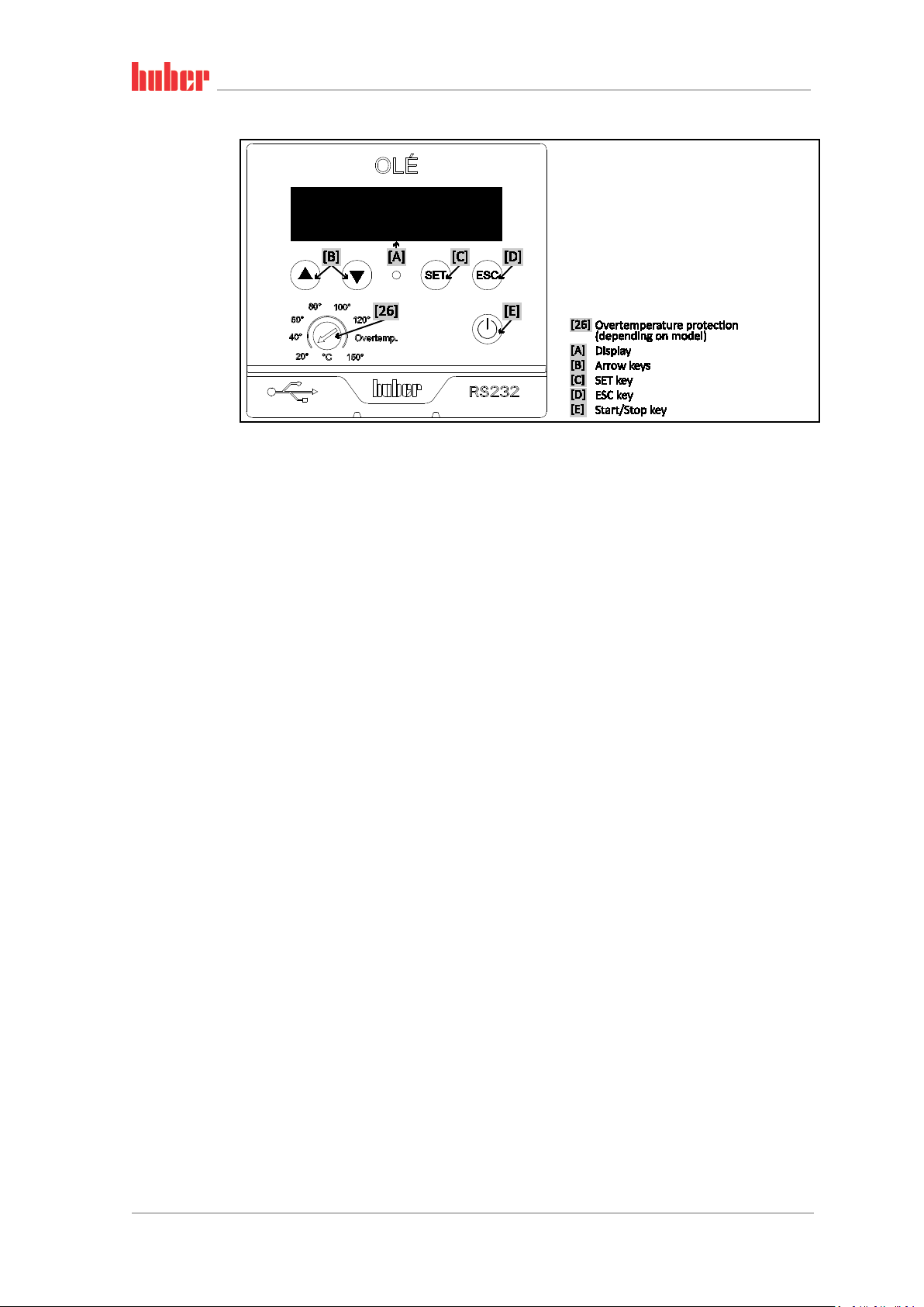
The control panel:
Displays and keys
Minichiller® OLÉ, Unichiller® OLÉ V1.2.0en/12.01.18//1.0.0

7
OPERATION MANUAL
Table of contents
V1.2.0en/12.01.18//1.0.0
1 Introduction 12
1.1 Details on the declaration of conformity ....................................................... 12
1.2 Safety .......................................................................................................... 12
1.2.1 Symbols used for Safety Instructions .............................................................. 12
1.2.2 Proper operation ............................................................................................. 13
1.2.3 Reasonably foreseeable misuse ...................................................................... 13
1.3 Responsible bodies and operators – Obligations and requirements............... 14
1.3.1 Obligations of the responsible body ............................................................... 14
1.3.1.1 Proper disposal of resources and consumables ......................................... 14
1.3.1.2 Temperature control unit with natural refrigerants (NR) .......................... 15
1.3.1.3 Temperature control units with fluorinated greenhouse gases/refrigerants17
1.3.2 Requirements for operators ........................................................................... 17
1.3.3 Obligations of the operators ........................................................................... 17
1.4 General information ..................................................................................... 17
1.4.1 Description of workstation ............................................................................. 17
1.4.2 Safety devices to DIN 12876 ........................................................................... 18
1.4.2.1 Mechanical overtemperature protection ................................................... 18
1.4.2.2 Low level protection ................................................................................... 18
1.4.3 Further protective devices .............................................................................. 19
1.4.3.1 Power interruption ..................................................................................... 19
1.5 Exemplary illustrations of the cooling variants .............................................. 19
1.5.1 Air cooling ....................................................................................................... 19
1.5.2 Water cooling .................................................................................................. 20
1.5.3 Consequence of inadequate energy dissipation ............................................. 20
2 Commissioning 21
2.1 In-plant transport ......................................................................................... 21
2.1.1 Lifting and transporting the temperature control unit ................................... 21
2.1.1.1 Temperature control unit with lifting eyes ................................................ 21
2.1.1.2 Temperature control unit without lifting eyes ........................................... 22
2.1.2 Positioning the temperature control unit ....................................................... 22
2.1.2.1 Temperature control unit with casters ...................................................... 22
2.1.2.2 Temperature control unit without casters ................................................. 22
2.2 Unpacking .................................................................................................... 22
2.3 Ambient conditions ...................................................................................... 23
2.3.1 EMC-specific notes .......................................................................................... 24
2.4 Installation conditions .................................................................................. 24
2.5 Recommended temperature control and cooling water hoses ...................... 25
2.6 Wrench sizes and torques ............................................................................. 25
2.7 Temperature control units with water cooling .............................................. 25
2.8 Preparations for operation ........................................................................... 27
2.8.1 Unscrewing/activating the leveling feet (if any) ............................................. 27
2.8.2 Opening/closing the bypass valve ................................................................... 27
2.8.3 Enable / Disable silent operation (optional) ................................................... 28
2.9 Connecting externally closed application ...................................................... 28
2.9.1 Connecting an externally closed application .................................................. 28
2.10 Connecting to the power supply ................................................................... 29
V1.2.0en/12.01.18//1.0.0 Minichiller® OLÉ, Unichiller® OLÉ

OPERATION MANUAL
8
2.10.1 Connection using socket with protective earth (PE) ....................................... 29
2.10.2 Connection via hard wiring ............................................................................. 30
3 Function description 31
3.1 Function description of the temperature control unit ................................... 31
3.1.1 General functions ............................................................................................ 31
3.1.2 Other functions ............................................................................................... 31
3.2 Information on the thermal fluids ................................................................ 31
3.3 To be noted when planning the test ............................................................. 32
3.4 Display and control instruments ................................................................... 33
3.4.1 Display ............................................................................................................. 33
3.4.2 Control instruments ........................................................................................ 34
3.4.2.1 Arrow keys .................................................................................................. 34
3.4.2.2 SET key ........................................................................................................ 34
3.4.2.3 ESC key ....................................................................................................... 35
3.4.2.4 Start/Stop key ............................................................................................. 35
3.4.3 Adjusting settings ............................................................................................ 35
3.5 Menu function ............................................................................................. 36
3.6 Functional examples .................................................................................... 37
3.6.1 Selecting a language ....................................................................................... 37
3.6.2 Setting the setpoint ........................................................................................ 37
3.6.3 Changing the Auto-Start function ................................................................... 37
4 Setup mode 38
4.1 Setup mode ................................................................................................. 38
4.1.1 Turning on the temperature control unit ....................................................... 38
4.1.2 Setting the overtemperature (OT) protection ................................................ 38
4.1.2.1 General information on the overtemperature protection ......................... 38
4.1.2.2 Setting the overtemperature protection .................................................... 39
4.1.3 Testing the overtemperature protection for functionality ............................. 39
4.2 Filling, venting, degassing and draining ......................................................... 40
4.2.1 Filling and venting externally closed application ............................................ 40
4.2.1.1 Filling and venting with >Sight glass< [23] ................................................. 41
4.2.1.2 Filling and venting with >Level indicator and drain< [38] .......................... 42
4.2.2 Draining externally closed applications .......................................................... 43
4.2.2.1 Draining with >Sight glass< [23] ................................................................. 43
4.2.2.2 Draining with >Level indicator and drain< [38] .......................................... 44
5 Normal operation 45
5.1 Automatic operation .................................................................................... 45
5.1.1 Temperature control ....................................................................................... 45
5.1.1.1 Starting the temperature control process .................................................. 45
5.1.1.2 Ending the temperature control process ................................................... 45
6 Interfaces and data communication 46
6.1 Controller interfaces .................................................................................... 46
6.1.1 USB-2.0 interface ............................................................................................ 46
6.1.1.1 USB-2.0 interface, device ........................................................................... 46
6.1.2 RS232 jack ....................................................................................................... 46
6.2 Interfaces on the temperature control unit (optional) ................................... 46
6.2.1 RS232 jack ....................................................................................................... 47
6.2.2 Connection jack for Pt100 process display sensor .......................................... 47
6.2.3 Jack ECS (External Control Signal) standby ..................................................... 47
Minichiller® OLÉ, Unichiller® OLÉ V1.2.0en/12.01.18//1.0.0

9
OPERATION MANUAL
6.2.4 Connector POKO (floating contact) alarm ...................................................... 48
6.3 Data communication .................................................................................... 48
6.3.1 LAI commands ................................................................................................. 49
6.3.1.1 Command “V” (Verify) ................................................................................ 49
6.3.1.2 Command “L” (Limit) .................................................................................. 50
6.3.1.3 Command “G” (General) ............................................................................ 50
6.3.2 PP commands .................................................................................................. 52
7 Service/maintenance 53
7.1 Displays in the event of faults ....................................................................... 53
7.2 Maintenance ................................................................................................ 54
7.2.1 Function check and visual inspection ............................................................. 54
7.2.2 Replacing temperature control or coolant hoses ........................................... 55
7.2.2.1 Replacing temperature control hoses ........................................................ 55
7.2.2.2 Replacing coolant hoses ............................................................................. 55
7.2.3 Clean liquefier fins (air-cooled temperature control unit) ............................. 56
7.2.4 Clean hat-type strainer (dirt trap) (water-cooled temperature control unit) . 57
7.3 Thermal fluid inspection, replacement and circuit cleaning ........................... 57
7.3.1 Thermal fluid replacement ............................................................................. 58
7.3.1.1 Externally closed application ...................................................................... 58
7.3.2 Rinsing the thermal fluid circuit ...................................................................... 58
7.3.2.1 Rinsing a thermofluid circuit with >Sight glass< [23] ................................. 58
7.3.2.2 Rinsing the thermofluid circuit with >Level indicator and drain< [38] ....... 59
7.4 Cleaning the surfaces ................................................................................... 60
7.5 Inspect the mechanical seal .......................................................................... 60
7.6 Plug contacts ................................................................................................ 61
7.7 Decontamination/repairs ............................................................................. 61
8 Shutting down 62
8.1 Safety instructions and basic principles ........................................................ 62
8.2 Switch-off .................................................................................................... 62
8.3 Draining the cooling water ........................................................................... 63
8.3.1 Draining process ............................................................................................. 63
8.4 Packing ........................................................................................................ 63
8.5 Shipping ....................................................................................................... 63
8.6 Disposal ....................................................................................................... 64
8.7 Phone number and company address ........................................................... 65
8.7.1 Telephone number: Customer Support .......................................................... 65
8.7.2 Telephone number: Sales ............................................................................... 65
8.7.3 Email address: Customer Support ................................................................... 65
8.7.4 Service/return address .................................................................................... 65
8.8 Certificate of Compliance ............................................................................. 65
9 Annex 66
V1.2.0en/12.01.18//1.0.0 Minichiller® OLÉ, Unichiller® OLÉ

OPERATION MANUAL
10
Minichiller® OLÉ, Unichiller® OLÉ V1.2.0en/12.01.18//1.0.0

OPERATION MANUAL
11
Foreword
Dear Customer,
Thank you for choosing a temperature control unit from Peter Huber Kältemaschinenbau AG. You
have made a good choice. Thank you for your trust.
Please read the operation manual carefully before putting the unit into operation. Strictly follow all
notes and safety instructions.
Follow the operation manual with regard to transport, start-up, operation, maintenance, repair,
storage and disposal of the temperature control unit.
We fully warrant the temperature control unit for the specified normal operation.
The models listed on page 5 are referred to in this operation manual as temperature control units
and Peter Huber Kältemaschinenbau AG as Huber company or Huber.
Liability for errors and misprints excluded.
The following trademarks and the Huber logo are registered trademarks of Peter Huber Kältemaschinenbau AG
in Germany and/or other countries worldwide: BFT®, CC®, CC-Pilot®, Com.G@te®, Compatible Control®,
CoolNet®, DC®, E-grade®, Grande Fleur®, KISS®, Minichiller®, Ministat®, MP®, MPC®, Peter Huber Minichiller®,
Petite Fleur®, Pilot ONE®, RotaCool®, Rotostat®, SpyControl®, SpyLight®, Tango®, TC®, UC®, Unical®, Unichiller®,
Unipump®, Unistat®, Unistat-Pilot®, Unistat Tango®, Variostat®, Web.G@te®. The following trademarks are
registered in Germany to DWS Synthesetechnik: DW-Therm®, DW-Therm HT®
V1.2.0en/12.01.18//1.0.0 Minichiller® OLÉ, Unichiller® OLÉ
Introduction
12
OPERATION MANUAL Chapter 1
1 Introduction
1.1 Details on the declaration of conformity
The equipment complies with the basic health and safety requirements of the European Directives
listed below:
▪ Machinery Directive 2006/42/EC
▪ Low Voltage Directive 2006/95/EC
▪ EMC Directive 2004/108/EC
1.2 Safety
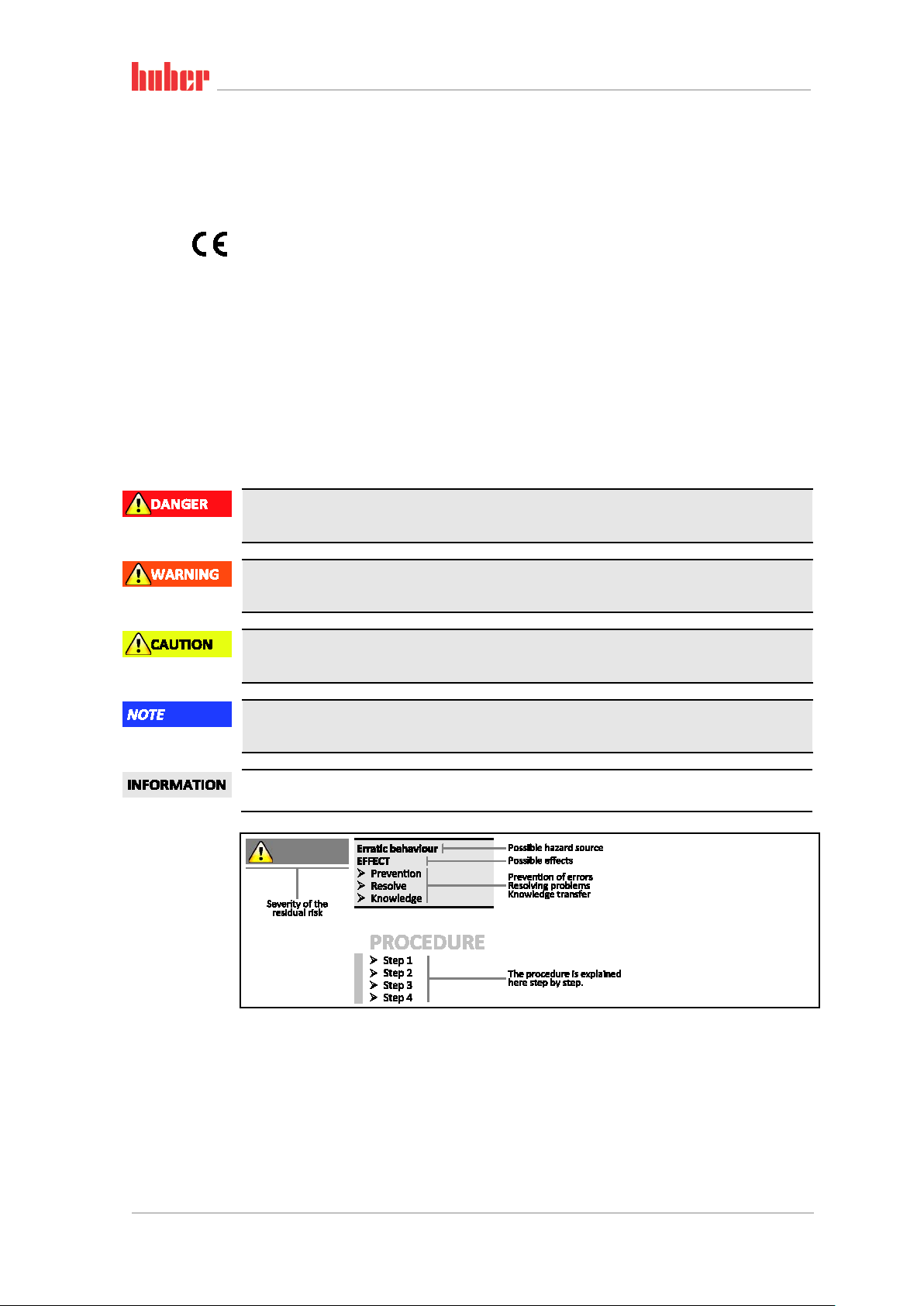
1.2.1 Symbols used for Safety Instructions
Safety instructions are marked by the below combinations of pictograms and signal words. The
signal word describes the classification of the residual risk when disregarding the operation manual.
Denotes an immediate hazardous situation that will result in death or serious injuries.
Safety information and
procedure
Denotes a general hazardous situation that may result in death or serious injuries.
Denotes a hazardous situation that can result in injury.
Denotes a situation that can result in property material damage.
Denotes important notes and usable hints.
The safety information in this operation manual is designed to protect the responsible body, operator and the equipment from damage. Safety information must always appear BEFORE instructions
and at the beginning of each chapter. You should be first informed about the residual risks due to
misuse before you begin an operation.
Minichiller® OLÉ, Unichiller® OLÉ V1.2.0en/12.01.18//1.0.0

Introduction
13
Do NOT install or start up the temperature control unit within an ATEX zone.
ages!
Do not ignore, bypass, dismantle or disconnect any safety devices!
Chapter 1 OPERATION MANUAL
1.2.2 Proper operation
Operating the temperature control unit in a potentially explosive area
DEATH THROUGH EXPLOSION
Improper use
SERIOUS INJURY AND PROPERTY DAMAGE
Store the operation manual where it is easy to access in close proximity to the temperature
control unit.
Only adequately qualified operators may work with the temperature control unit.
Operators must be trained before handling the temperature control unit.
Check that the operators have read and understood the operation manual.
Define precise responsibilities of the operators.
Personal protective equipment must be provided to the operators.
Be sure to follow the responsible body’s safety rules to protect life and limb and to limit dam-
Modifications to the temperature control unit by third-parties
DAMAGE TO THE TEMPERATURE CONTROL UNIT
Do not allow third parties to make technical modifications to the temperature control unit.
In case of any modification of the temperature control unit not approved by the manufacturer,
the CE declaration of conformity becomes invalid.
Only specialists trained by the manufacturer may carry out modifications, repairs or mainte-
nance work.
The following must be observed without fail:
Only use the temperature control unit in a fault-free condition!
Have start-up and repairs carried out only by specialists!
The temperature control unit must not be used for any purposes other than temperature control in
accordance with the operation manual.
The temperature control unit is manufactured for industrial use. The temperature control unit maintains the temperature of certain applications, including glass or metal reactors or other expedient
items in laboratories and industry. Flow-through coolers and calibration baths must be used only in
combination with Huber temperature control units. Thermal fluids suitable for the overall system
are used. The chilling and heating capacity is provisioned at the pump connections or - where present - in the tempering bath. The technical specification of the temperature control unit is given in
the data sheet (from page 66 in section »Annex«). The temperature control unit must be installed,
configured and operated according to the handling instructions in this operating manual. Failure to
comply with the operation manual is deemed improper use. The temperature control unit conforms
to state-of-the-art technology and the recognized safety regulations. Safety devices are built into
your temperature control unit.
1.2.3 Reasonably foreseeable misuse
Use with medical devices (e.g. in Vitro diagnostic procedure) or for direct foodstuff temperature
control is NOT permissible.
The temperature control unit must NOT be used for any purposes other than temperature control in
accordance with the operation manual.
The manufacturer accepts NO liability for damage caused by technical modifications to the temper-
ature control unit, improper handling or use of the temperature control unit if the operation manual is not observed.
V1.2.0en/12.01.18//1.0.0 Minichiller® OLÉ, Unichiller® OLÉ
Introduction
14
OPERATION MANUAL Chapter 1
1.3 Responsible bodies and operators – Obligations and
requirements
1.3.1 Obligations of the responsible body
The operation manual is to be stored where it is easy to access in close proximity to the temperature
control unit. Only adequately qualified operators (e.g. chemists, CTA, physicists etc.) are permitted
to work with the temperature control unit. Operators must be trained before handling the temperature control unit. Check that the operators have read and understood the operation manual. Define
precise responsibilities of the operators. Personal protective equipment must be provided to the
operators.
▪ The responsible body must install a condensation water / thermofluid drip tray below the tem-
perature control unit.
▪ The responsible body must check whether national regulations require the mandatory installation
of a drain tray for the installation area of the temperature control unit/the entire system.
▪ Our temperature control unit complies with all applicable safety standards.
▪ Your system, which uses our temperature control unit, must be as safe.
▪ The responsible body must design the system so as to ensure it is safe.
▪ Huber is not responsible for the safety of your system. The responsible body is responsible for the
safety of the system.
▪ Whilst the temperature control unit provided by Huber meets all the applicable safety standards,
integration into a system may give rise to hazards that are characteristic of the other system’s design and beyond the control of Huber.
▪ It is the responsibility of the system integrator to ensure that the overall system, into which this
temperature control unit is integrated, is safe.
▪ The >Mains isolator< [36] (if present) may be provided with a facility to lock the main isolator in
the off position to facilitate safe system installation and maintenance of the temperature control
unit. It is the responsibility of the responsible body to develop any lock-out/tag-out procedure in
accordance with local regulations (e.g. CFR 1910.147 for the US).
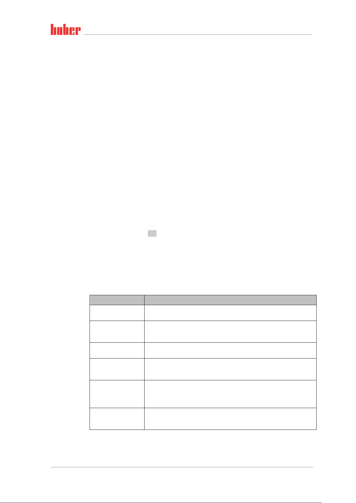
1.3.1.1 Proper disposal of resources and consumables
Do comply with all national disposal regulations applicable for you. Contact your local waste management company for any questions concerning disposal.
Overview
Material / Aids Disposal / Cleaning
Temperature control
unit packaging material
Thermal fluid
Filling accessories, e.g.
beaker
Aids such as towels,
cleaning cloths
Cleaning agents such as
stainless steel cleaning
agents, sensitive-fabrics
detergents
Consumables such as air
filter mats, temperature
control hoses
Keep the packaging material for future use (e.g. transport).
Please refer to the safety data sheet of the thermal fluid used for information on its
proper disposal.
Use the original thermal fluid container when disposing it.
Clean the filling accessories for reuse. Make sure that the materials and cleaning
agents used are properly disposed of.
Tools used to take up spilled thermal fluid must be disposed of in the same fashion
as the thermal fluid itself.
Tools used for cleaning must be disposed of depending on the cleaning agent used.
Please refer to the safety data sheet of the cleaning agent used for information on its
proper disposal.
Use the original containers when disposing of large quantities of cleaning agents.
Please refer to the safety data sheet of the consumables used for information on
their proper disposal.
Minichiller® OLÉ, Unichiller® OLÉ V1.2.0en/12.01.18//1.0.0
Introduction
15
The temperature control unit is not approved for operation in an ATEX zone.
Chapter 1 OPERATION MANUAL
1.3.1.2 Temperature control unit with natural refrigerants (NR)
Over 8 g refrigerant per m³ room air
DEATH OR SERIOUS INJURY DUE TO EXPLOSION
Observe the rating plate (amount of natural refrigerant contained) and the room size (maxi-
mum room concentration of natural refrigerant in case of leakage) when installing the temperature control unit.
Over 8 g refrigerant per m³ room air: A gas warning sensor must be fitted and functioning.
The gas warning sensor must be calibrated and maintained at regular intervals (between 6 and
12 months).
Huber products with natural refrigerants work with numerous proven, safe and highly-sustainable
technologies. The relevant standards and regulations for temperature control units with natural
refrigerants contain a number of stipulations, the importance of complying with which is set out
below. Also observe on page 13 the section »Proper operation«.
Huber temperature control units are constructed to be permanently sealed and are carefully
checked for leak tightness. Temperature control units with more than 150 g natural refrigerant are
equipped with an additional gas warning sensor. To find out whether your temperature control unit
is equipped with a gas warning sensor, refer to the data sheet from page 66 in section »Annex«.
The fill quantity of your temperature control unit is stated on the data sheet (from page 66 in section »Annex«) or on the rating plate on the rear of the temperature control unit. Observe page 23,
section »Ambient conditions« and page 24, section »Installation conditions«.
Classifying the applica-
tion field
Class of
application
field
A General
B Monitored Laboratories 2.5 kg
C
Temperature control units with more than 1 kg refrigerant must not be installed below ground level (GL).
Application field
Access only for
authorized
persons
Example of the installation
location
Publicly accessible area in a
public building
Production equipment 10.0 kg
Max.
quantity of
refrigerant
3
8 g/m
ambient air
Max. permissible
quantity above
ground level (GL)
1.5 kg
AND
Temperature control units with up to 150 g natural refrigerant
▪ The temperature control unit has been constructed to the requirements of EU and EFTA coun-
tries.
▪ Use the table as guidance for classifying the application field. Respect the max. refrigerant quanti-
ty stated therein.
Temperature control units WITH pre-installed gas warning sensor and > 150 g natural refrigerant
▪ The temperature control unit has been constructed to the requirements of EU and EFTA coun-
tries.
▪ Use the table as guidance for classifying the application field. Respect the max. refrigerant quanti-
ty or the permissible highest quantity above ground level (GL) stated therein.
▪ Ventilation with optional supply and exhaust air connection: Use the temperature control unit’s
supply and exhaust air connection to connect it to the building’s exhaust system (see wiring diagram from page 66 in Section »Annex«). First, remove the cover to the air inlet connection; an air
filter mat is installed behind it. This air filter mat must be checked / replaced at regular intervals
so that the air flowing into the temperature control unit is not reduced (see page 54, Section
»Function check and visual inspection«). Connect the building’s exhaust system with the temperature control unit’s exhaust air port. The cover of the supply air port mustnot be removed if the
exhaust system provided in a building is not used.
V1.2.0en/12.01.18//1.0.0 Minichiller® OLÉ, Unichiller® OLÉ

Introduction
16
The temperature control unit is not approved for operation in an ATEX zone.
OPERATION MANUAL Chapter 1
▪ The mounting plate for mounting a gas warning sensor is located inside the temperature control
unit in the vicinity of the >Cable entry gas warning sensor<[100].
▪ For the position of the >Cable entry gas warning sensor< [100], please refer to the wiring diagram
from page
▪ Additional information on the pre-installed gas detection sensor:
- The built-in gas detection sensor enables a safety shutdown at 20% of the lower explosive
- A 24 V DC external power supply must be available for the pre-installed gas warning sen-
- The responsible body is responsible for the calibration of the gas detection sensor prior to
Temperature control units WITHOUT pre-installed gas warning sensor and > 150 g natural refrigerant
Over 8 g refrigerant per m³ room air
DEATH OR SERIOUS INJURY DUE TO EXPLOSION
Observe the rating plate (amount of natural refrigerant contained) and the room size (maxi-
mum room concentration of natural refrigerant in case of leakage) when installing the temperature control unit.
Over 8 g refrigerant per m³ room air: A gas warning sensor must be fitted and functioning.
The gas warning sensor must be calibrated and maintained at regular intervals (between 6 and
12 months).
66 in Section »Annex«.
limit via a power disconnect relay that is to be installed by the responsible body. The
temperature control unit is thus switched off early and safely in case of fault.
sor. The alarm output of the gas warning sensor uses a 4 - 20 mA signal. Please refer to the
data sheet of the gas warning sensor for further technical information. A separate pro-
cessing unit is available as an accessory for the control of the power disconnect relay. The
processing unit provides a potential-free switching contact and simultaneously supplies
power to and analyzes the gas warning sensor. Both variants require the responsible body
to provide the necessary dimensioning and installation. Please refer to the data sheet of
the gas warning sensor for the technical installation information. The alarm of the gas detection system can be connected to the responsible body’s alarm control unit. The responsible body is responsible for this and other measures.
initial operation and the observance of calibration and maintenance intervals specified in
the operating manual. We recommend to set calibration and maintenance intervals between 6 and 12 months if no information is provided. For increased safety requirements,
shorter intervals can be specified. On request, we will recommend a specialist company to
carry out calibration and maintenance.
▪ The temperature control unit has been constructed to the requirements of EU and EFTA coun-
tries.
▪ Use the table as guidance for classifying the application field. Respect the max. refrigerant quanti-
ty or the permissible highest quantity above ground level (GL) stated therein.
▪ Ventilation with optional supply and exhaust air connection: Use the temperature control unit’s
supply and exhaust air connection to connect it to the building’s exhaust system (see wiring diagram from page 66 in Section »Annex«). First, remove the cover to the air inlet connection; an air
filter mat is installed behind it. This air filter mat must be checked / replaced at regular intervals
so that the air flowing into the temperature control unit is not reduced (see page 54, Section
»Function check and visual inspection«). Connect the building’s exhaust system with the temperature control unit’s exhaust air port. The cover of the supply air port mustnot be removed if the
exhaust system provided in a building is not used.
▪ NO gas warning sensor is installed in this temperature control unit! Make sure that the installa-
tion site of the temperature control unit is sufficiently protected in the event of malfunction.
These include:
- Installation of a gas warning sensor for the building (room monitoring).
- Permanent ventilation of the temperature control unit and/or the installation site.
- All-pole disconnection in the event of malfunction of the temperature control unit.
Minichiller® OLÉ, Unichiller® OLÉ V1.2.0en/12.01.18//1.0.0

Introduction
17
Chapter 1 OPERATION MANUAL
1.3.1.3 Temperature control units with fluorinated greenhouse gases/refrigerants
F gases regulation (EC) No. 517/2014 of April 16, 2014, on fluorinated greenhouse gases, and re-
pealing Regulation (EC) No. 842/2006.
These regulations deal with all systems that contain fluorinated refrigerants. The substances dealt
with in Directive (EC) No. 1005/2009 of the European Parliament and of the Council of 16 September
2009 that deplete the ozone layer are excluded (CFC/HCFC).
The directive regulates the reduction of the emission, utilization, recovery, and destruction of certain fluorinated greenhouse gases. It also regulates the identification and disposal of products and
devices that contain these gases. Since July 4, 2007, responsible bodies must check their stationary
refrigeration systems for leaks at regular intervals, and have any leaks eliminated immediately.
Directive (EC) No. 303/2008 contains stipulations on the training and certification of companies and
personnel that are permitted to execute the specified activities.
Obligations of the responsible bodies:
▪ Directive (EC) No. 842/2006 already imposed a number of obligations upon responsible bodies
regarding certain fluorinated greenhouse gases. The new Ordinance on Fluorinated Greenhouse
Gases upholds these to a large extent. Some duties are added while others are designed differently by this new ordinance. Please refer to the text of this ordinance for a complete overview of the
individual responsibilities of responsible bodies.
▪ General obligation to reduce emissions.
▪ Only certified companies may maintain, repair or decommission refrigeration systems. The re-
sponsible bodies must verify that these companies are certified.
▪ Regular leak tests of stationary refrigeration systems by certified personnel (such as Huber service
engineers). The required test interval is based on the refrigerant filling capacity and the type of
refrigerant, converted to CO
▪ Responsibility of responsible bodies operating a plant to recover F-gases by certified personnel.
▪ Obligatory documentation requirement in the refrigeration system’s operation manual, specifying
type and volume of refrigerant used or recovered. The responsible body must keep the records
for at least 5 years after their creation and present it to the responsible authority upon request.
▪ Temperature control units with natural refrigerants (NR) are exempt from this Directive.
▪ Please refer to the data sheet or name plate of your temperature control unit for the quantity and
type of refrigerant.
▪ Additional information about the definition of the inspection interval can be found on our web-
site.
2 equivalent.
2
1.3.2 Requirements for operators
Work on the temperature control unit is reserved for appropriately qualified specialists, who have
been assigned and trained by the responsible body to do so. Operators must be at least 18 years old.
Under 18-year olds may operate the temperature control unit only under the supervision of a qualified specialist. The operator is responsible vis-a-vis third-parties in the work area.
1.3.3 Obligations of the operators
Carefully read the operation manual before operating the temperature control unit. Please observe
the safety instructions. When operating the temperature control unit, wear appropriate personal
protective equipment (e.g. safety goggles, protective gloves, non-slip shoes).
1.4 General information
1.4.1 Description of workstation
The workstation is located at the control panel in front of the temperature control unit. The workstation is determined by the customer's connected peripheries. Accordingly, it must be designed
safe by the responsible body. The workstation design also depends on the applicable requirements
of the German occupational health and safety regulations [BetrSichV] and the risk analysis for the
workstation.
V1.2.0en/12.01.18//1.0.0 Minichiller® OLÉ, Unichiller® OLÉ
Introduction
18
OPERATION MANUAL Chapter 1
1.4.2 Safety devices to DIN 12876
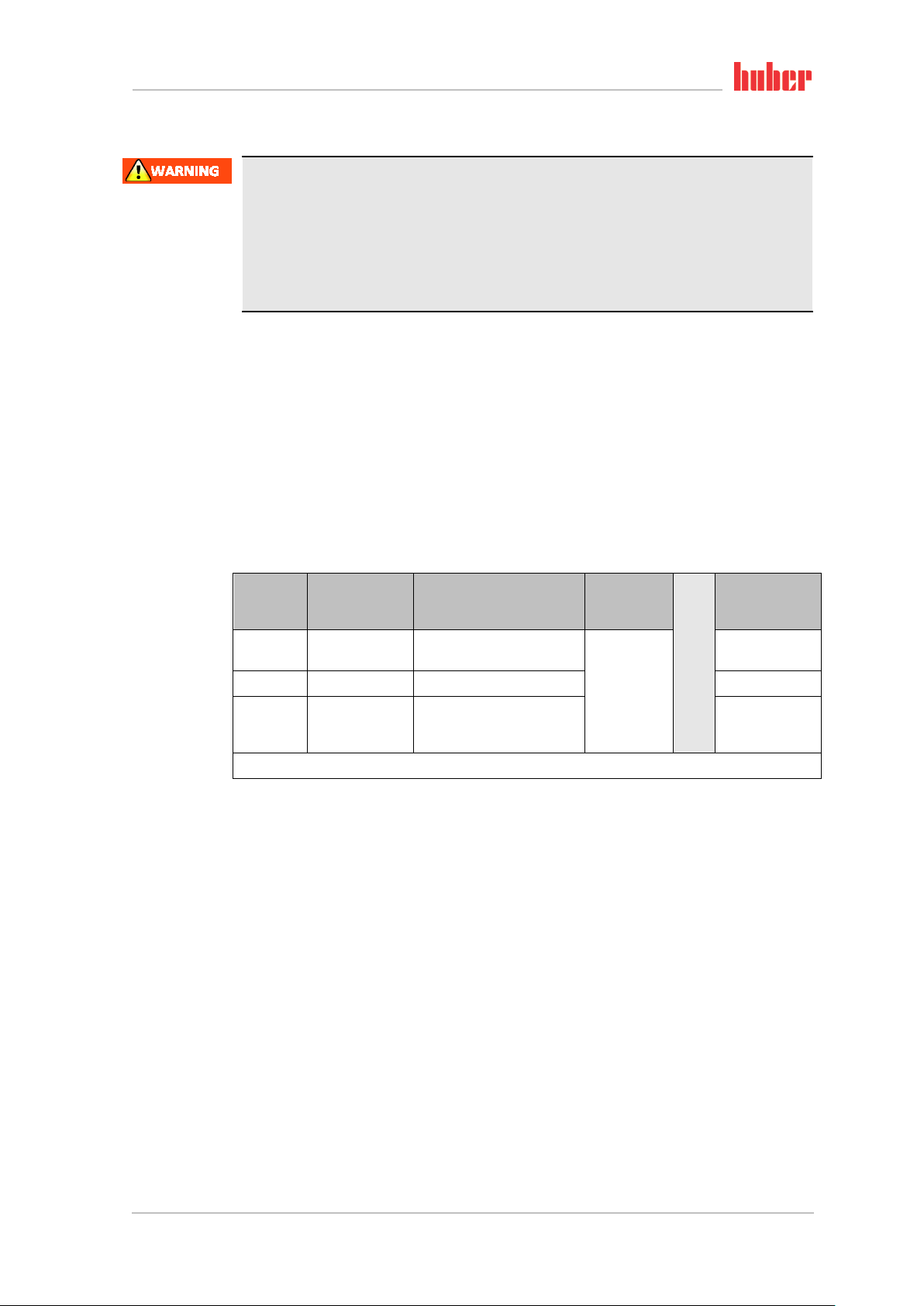
The rating of your temperature control unit is stated on the data sheet in the appendix.
Rating of laboratory
thermostats and
laboratory baths
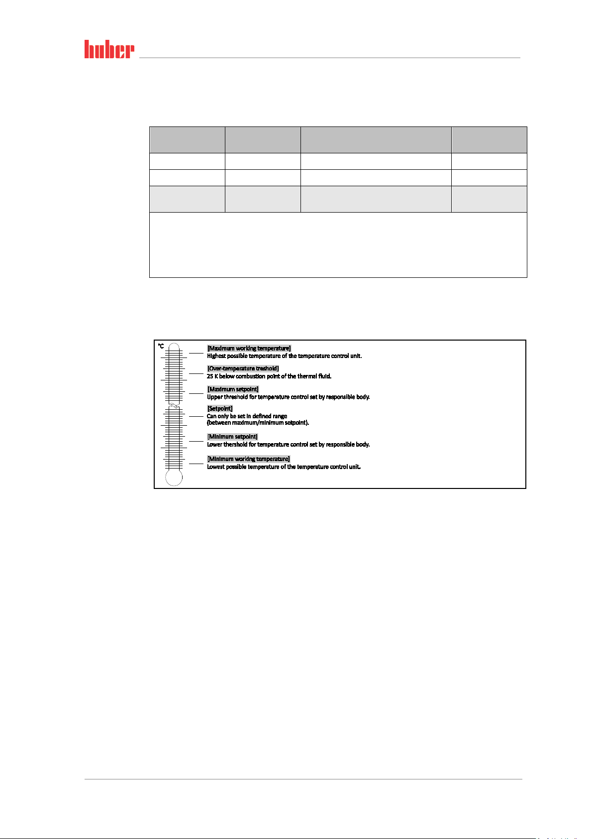
Overview of the tem-
perature thresholds
Classification
I Non-combustible a) Overheat protection c) NFL
II Combustible b) Adjustable overheat protection FL
III Combustible b)
a)
Usually water; other fluids only if non-combustible even within the temperature range of an individual fault.
b)
The temperature control media must have a combustion point of ≥ 65 °C.
c)
The overheat protection can, for instance, can be realized using a suitable fill level sensor or a suitable temper-
ature limiter.
d)
Optional at the choice of the manufacturer.
▪ Temperature control units with heating correspond to class number III/FL. These temperature
control units are characterized by an “H” in the device name.
▪ Temperature control units without heating correspond to class number I/NFL.
Temperature
control medium
Technical requirements Identification d)
Adjustable overtemperature protection
and additional low-level protection
FL
1.4.2.1 Mechanical overtemperature protection
Only temperature control units with a heater are fitted with a mechanical overtemperature protection. Set the overtemperature protection as described on page 38 in section »Setting the overtem-
perature (OT) protection«.
1.4.2.2 Low level protection
Minichiller with heater: A mechanical float is used for level monitoring. A floating body, which is
guided in a device, floats on the surface of the thermal fluid. Depending on the level of the thermal
fluid, the float device signals the electronics a state of good (in case of sufficient filling) or a state of
bad (in case of insufficient filling).The functionality of the float is checked at regular intervals during
continuous operation.
Unichiller with heater: The low level protection operates via a pressure sensor in the thermal fluid
circuit. The pump and the thermal fluid provide the required pressure at the pressure sensor. Air in
the system (fill level too low, inadequately vented) prevents the pressure from reaching the value
specified at the pressure sensor. Temperature control and circulation are interrupted.
Minichiller® OLÉ, Unichiller® OLÉ V1.2.0en/12.01.18//1.0.0
Introduction
19
Chapter 1 OPERATION MANUAL
1.4.3 Further protective devices
Emergency strategy – isolate the power supply!
Disconnect the temperature control unit from the power supply!
1.4.3.1 Power interruption
Following a power outage (or when switching on the temperature control unit), this function can be
used to determine how the temperature control unit is supposed to respond.
Auto-Start function is turned off
The temperature control is started only by manual input when the temperature control unit is
turned on.
Auto-Start function is turned on
The temperature control unit is set to the same state it was in before the power outage. For example, before the power outage: Thermoregulation is off; after power outage: Thermoregulation is off.
If temperature control is active during a power outage, the process will automatically continue after
the power outage.
Further information can be found on page 37 in section »Changing the Auto-Start function«.
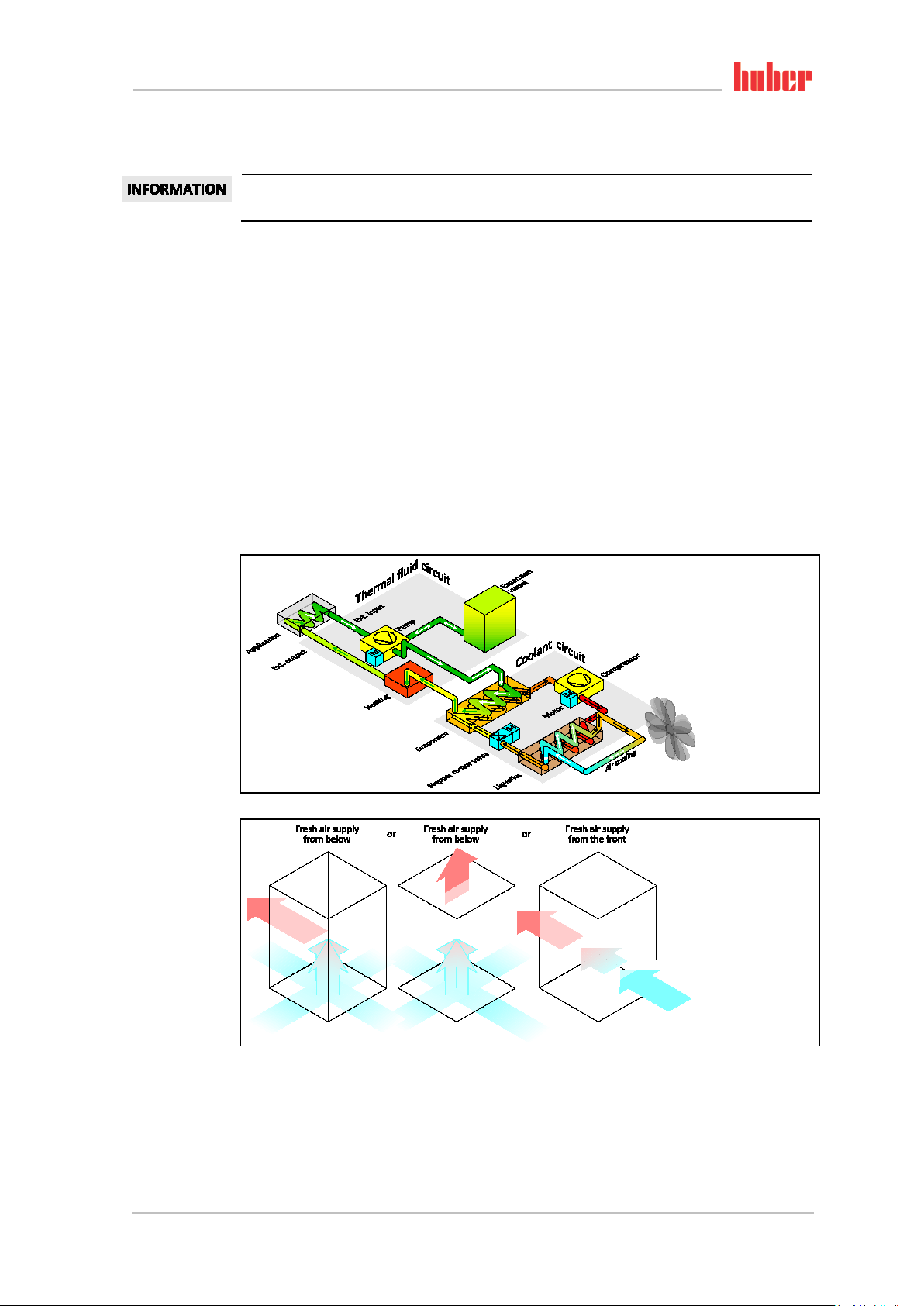
1.5 Exemplary illustrations of the cooling variants
1.5.1 Air cooling
Example: Air cooling
Air inlet
V1.2.0en/12.01.18//1.0.0 Minichiller® OLÉ, Unichiller® OLÉ
Introduction
20
OPERATION MANUAL Chapter 1
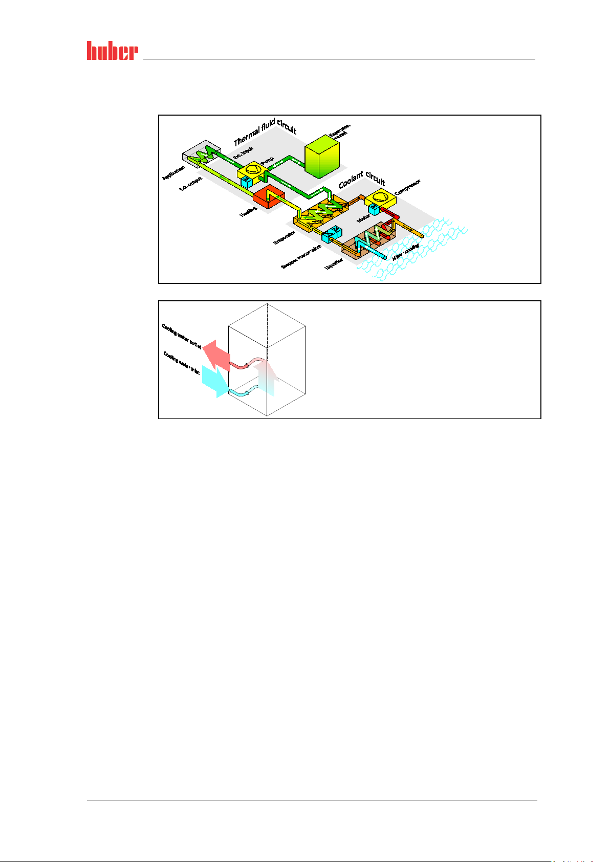
1.5.2 Water cooling
Example: Water cool-
ing
Water connection
1.5.3 Consequence of inadequate energy dissipation
Room air/cooling water
Consequences of, for instance, contamination of the liquefier fins, inadequate clearance between
temperature control unit to wall/bath wall, room air/cooling water too warm, cooling water differential pressure too low, suction strainer contamination: The refrigerant in the coolant circuit can no
longer fully discharge the admitted energy to the room air/cooling water. Thus there is not sufficient
liquefied refrigerant available, the condensation temperature and the energy consumption to rise.
Coolant circuit
Consequences of inadequate refrigerant quantity/rising condensation temperature: Not all the
cooling capacity from the coolant circuit is available at the evaporator. This means reduced energy
transmission from the thermal fluid circuit.
Thermal fluid circuit
Consequence of inadequate energy dissipation from the thermal fluid: The thermal fluid can only
dissipate the energy from your application to a limited extent.
Application
Consequences of inadequate energy dissipation from the application: The energy created (exothermic) in the application can no longer be fully dissipated.
Temperature control unit
An electronically-controlled expansion valve is used in the temperature control unit to optimize the
power adjustment. The expansion valve always provisions the maximum possible cooling capacity
within the permissible ambient temperature range. The temperature control unit switches off when
the upper range is reached (maximum permissible ambient temperature).
Minichiller® OLÉ, Unichiller® OLÉ V1.2.0en/12.01.18//1.0.0

Commissioning
21
activated parking brake!
Only transport the temperature control unit in an upright position.
weight of the temperature control unit into account.
Chapter 2 OPERATION MANUAL
2 Commissioning
2.1 In-plant transport
Temperature control unit is not transported / moved according to the specifications in this operation manual
DEATH OR SERIOUS INJURY DUE TO CRUSHING
Always transport / move the temperature control unit according to the specifications in this
operation manual.
Wear personal protective equipment during transport.
Always work with the specified number of persons when moving the temperature control unit
on casters (if any).
If the temperature control unit is equipped with casters and parking brakes:
2 parking brakes are always freely accessible when moving the temperature control unit. Activate the 2 parking brakes in an emergency!
If only one parking brake is activated on the casters in an emergency:
The temperature control unit is not stopped but rotates around the axis of the caster with the
Temperature control unit transported in a horizontal position
DAMAGE TO THE COMPRESSOR
▪ If available, use the lugs on the top side of the temperature control unit for transportation.
▪ Use an industrial truck for transport.
▪ The casters on the temperature control unit are not suitable for transport. The casters are sym-
metrically loaded with 25% of the total mass of the temperature control unit.
▪ Remove the packing material (e.g. the palette) only at the place of installation.
▪ Protect the temperature control unit from transport damage.
▪ Do not transport the temperature control unit alone and without aids.
▪ Check the load bearing capacity of the transportation route and the place of installation.
▪ The parking brakes must be activated at the casters (if any) and/or the leveling feet (if any) must
be unscrewed/activated before the temperature control unit is put into operation (see page 27,
section »Unscrewing/activating the leveling feet (if any)«).
2.1.1 Lifting and transporting the temperature control unit
2.1.1.1 Temperature control unit with lifting eyes
The temperature control unit is raised at the lifting eyes without load handling attachments
DAMAGE TO THE TEMPERATURE CONTROL UNIT
Always use load handling attachments when lifting and transporting the temperature control
unit.
The lifting eyes are only designed for a load without inclination (0°).
The load handling attachment used must be adequately dimensioned. Take the dimensions and
▪ Do not lift and transport the temperature control unit at the lifting eyes alone and without aids.
▪ Lift and transport the temperature control unit at the lifting eyes only with a crane or an industrial
truck.
▪ The crane or industrial truck must have a lifting force equal to or greater than the weight of the
temperature control unit. See the data sheet (from page 66 in section »Annex«) for the weight of
the temperature control unit.
V1.2.0en/12.01.18//1.0.0 Minichiller® OLÉ, Unichiller® OLÉ
 Loading...