

Page 1
SSSSEEEERRRRIIIIEEEESSSSSSSSMMMMAAAA
SSSSUUUUBBBBMMMMIIIINNNNIIIIAAAATTTTUUUURRRREEEECCCCOOOONNNNNNNNEEEECCCCTTTTOOOORRRRSSSS
Description
SUHNER SMA connectors are precision connectors for microwave applications up to 18 GHz/
26.5 GHz. They distinguish themselves through
their high mechanical strength, high durability,
high reliability and low VSWR.
SMA launchers are the preferred connection elementforvariedmicrowavecircuits.Thereisahuge
variety of applications for SUHNER SMA connectors, such as mobile communication, test & measurement, instruments, avionics, etc.
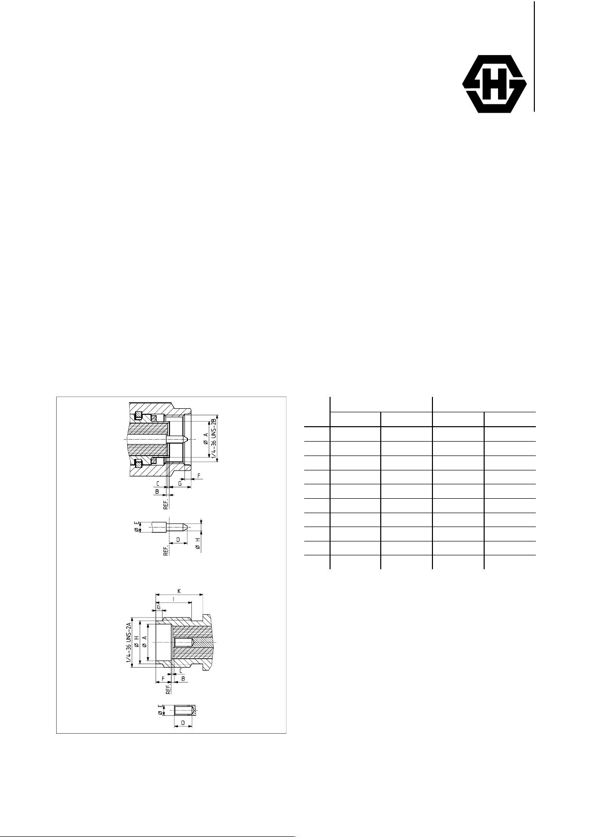
Interface Dimensions
Plug (male)
Jack (female)
Interface Dimensions in mm /
Plug Jack
min. max. min. max.
A --- 4.59/.
B 0.00/.
C 0.00/.
D --- 2.54/.
E 1.24/.
F 0.38/.
G --- 3.43/.
H 0.90/.
I --- --- 4.32/.
K --- --- 5.54/.
000
000
049
015
036
0.25/.
0.25/.
1.29/.
1.14/.
0.94/.
181
010
010
100
051
045
135
037
4.59/.
0.00/.
0.00/.
2.67/.
1.24/.
1.88/.
0.38/.
5.28/.
181
000
000
105
049
074
015
208
170
218
inches
---
0.25/.
010
0.25/.
010
---
1.29/.
051
1.98/.
078
1.14/.
045
5.49/.
216
---
---
SU HNERâ SMA
Page 2
Interface dimensions conformable to
the Standards:
International: IEC 169-15
Europe: CECC 22110
USA: MIL-C-39012, SMA
Interface MIL-STD-348a/310
GB: BS 9210 N 0006
F: NF-C-93563 (KMR)
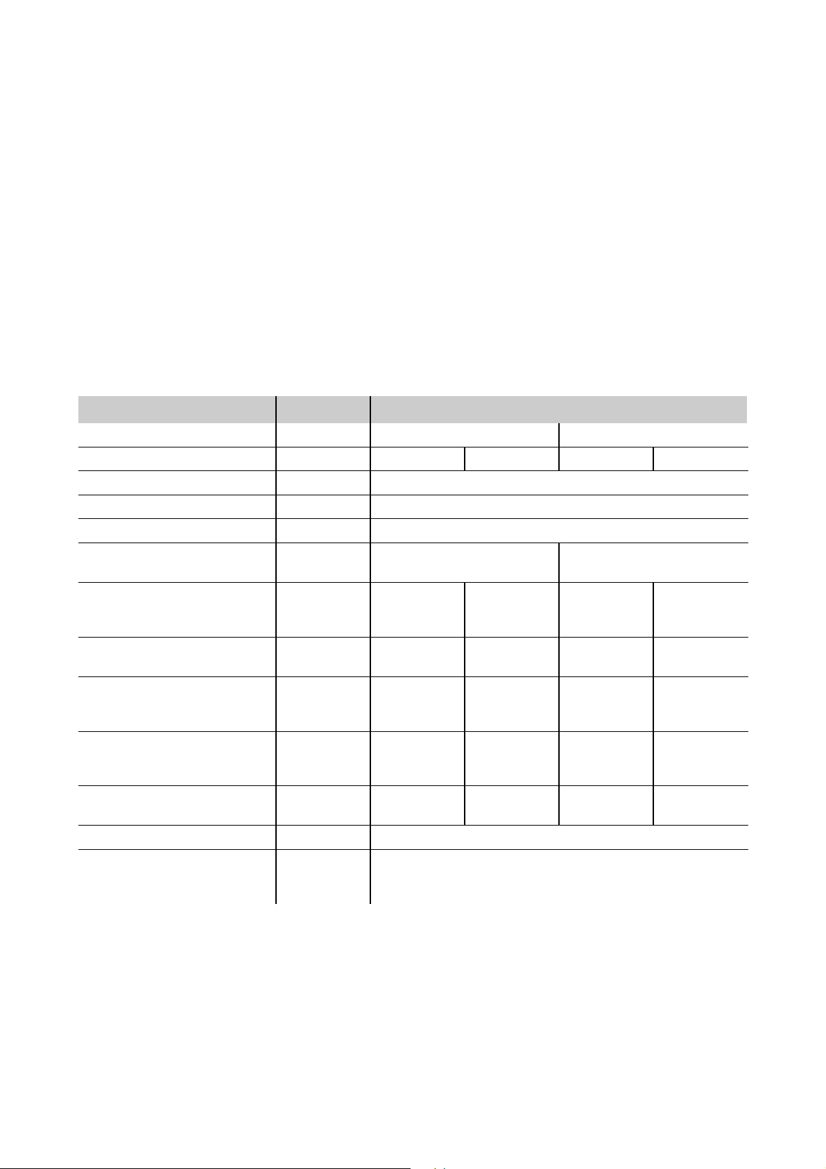
Technical Data
ELECTRICAL DATA
Cable type semi-rigid flexible
Cable dielectric diameter (mm/
Impedance 50 Ω
Frequency range for interface DC ... 18 GHz
VSWR (typical value) see table next page
RF-leakage measured
at 3 GHz (f in GHz)
Dielectric withstanding
voltage (at sea level,
in V rms, 50 Hz)
Working voltage (at sea level,
in V rms, 50 Hz)
Corona extinction voltage
(at 21 000 m/
in V rms, 50 Hz)
Working v ol tage
(at 21 000 m/
in V rms, 50 Hz)
RF withstanding voltage
at 5 MHz (V rms)
70 000 ft
70 000 ft
.,
.,
MIL-C-39012
in.
) 1.5 /
3.26 ≥ 100 dB-f ≥ 60 dB
3.17 1000 1500 750 1000
3.22 250 375 190 250
3.23 670 1000 500 670
.066
≤335 ≤500 ≤250 ≤335
≤85 ≤125 ≤65 ≤85
3/
.117
1.5 /
.066
3/
.117
Insulation resistance 3.11 ≥ 5·103MΩ
Contact resistance
- centre contact
-outercontact
3.16
≤ 3mΩ
≤ 2.5 mΩ
SU HNERâ SMA
Page 3

TYPICAL VSWR
CONNECTOR TYPE 1GHz 2.5 GHz 5GHz 12.4 GHz 18 GHz CABLE GROUP
straight connectors 1.03 1.03 1.03 1.07 1.08 Y3, Y11
1.03 1.03 1.04 1.07 1.15 Y5, Y12
1.05 1.07 1.08 U2, U4
1.04 1.05 1.07 U7, U9
right angle connectors 1.03 1.05 1.10 1.25 Y3, Y11
1.03 1.05 1.08 1.17 Y5, Y12
1.05 1.07 1.11 U2, U4
1.03 1.05 1.07 U7, U9
FREQUENCY RANGE
MECHANICAL DATA
Recommended coupling
nut torque
Coupling nut retention force 3.25 ≥ 270 N /
Contact captivation
-axial
2) While fastening the plug coupling nut, prevent the interface from rotating by holding the plug housing by hand.
MIL-C-39012 Gold/CuBe and stainless steel SUCOPLATEâ/brass
0.8 Nm ... 1.1 Nm /
7.1 in. lbs. ... 9.7 in. lbs
(max. 500 matings)
3.12 ≥ 27 N /
60.7 lbs
6.1 lbs
0.45 Nm /
0.70 Nm /
1.00 Nm /
≥ 270 N /
≥ 27 N /
4.0 in. lbs
6.0 in. lbs
8.8 in. lbs
60.7 lbs
6.1 lbs
ENVIRONMENTAL DATA
Temperature range –65°C ... +165°C/–85°
Climatic category IEC ! 55 / 155 / 21
Thermal shock 3.20 MIL-STD-202, Method 107, Condition B
Moisture resistance 3.21 MIL-STD-202, Method 106
MIL-C-39012
F ... +329°F
(max. 500 matings)
(max. 200 matings)
(max. 20 matings)
2)
Corrosion 3.13 Saltspray test acc. to MIL-STD-202, Method 101, Condition B
Vibration 3.18 MIL-STD-202, Method 204, Condition D
Shock 3.19 MIL-STD-202, Method 213, Condition I
SUHNERâSMA
Page 4

MATERIAL DATA
CONNECTOR PART STANDARDS MATERIAL PLATING
QQ-C-530
Bodies, outer contacts
Pin contact
Crimp ferrules
Socket contact
Insulators PTFE or PFA
Gaskets silicone rubber
ISO CuNi1Pb1P
QQ-S-763
QQ-B-626
QQ-C-530
QQ-B-626
SUHNERâspecification
QQ-B-626
QQ-C-530
ISO CuNi1Pb1P
beryllium-copper, hardened
copper (spring)
stainless steel
brass
beryllium-copper, hardened
brass
copper
brass
beryllium-copper, hardened
copper (spring)
gold
passivated
SUCOPLATE
gold
gold
gold
Material selection
Requirements
The pressure applied to the SMA outer contact area is extremely high:
â
Coupling nut torque Contact pressure
1.0 Nm /
1.7 Nm /
8.9 in. lbs
15.0 in. lbs
recommended torque 550 N/mm2/
coupling proof torque 980 N/mm2/
7.98 · 104psi
1.42 · 105psi
Inadequate strength of connector body material will result in a slight deformation of the outer contact.
Excessive reflections will occur as a result, above approximately 2 GHz.
SELECTION GUIDE
BERYLLIUM STAINLESS STEEL BRASS
Material beryllium-copper stainless steel brass
Plating gold SUCOPLATE
Features, applications
Recommended coupling nut torque
D highest quality and
reliability
D suitable for almost any
application
D outperforms gold plated
stainless steel
0.8 Nm ... 1.1 Nm /
7.1 in. lbs. ... 9.7 in. lbs
(max. 500 matings)
D suitable for direct mounting
on aluminium panels
0.8 Nm ... 1.1 Nm /
7.1 in. lbs. ... 9.7 in. lbs
(max. 500 matings)
D best price/performance ratio
D for commercial
applications only
0.45 Nm /
(max. 500 matings)
0.70 Nm /
(max. 200 matings)
1.00 Nm /
(max. 20 matings)
â
4.0 in. lbs
6.0 in. lbs
8.8 in. lbs
Some connectors may have a specification th at differs from the above mentioned data.
SU HNERâ SMA
 Loading...