

Page 1
SERIES QN, COAXIAL CONNECTORS
DESCRIPTION
HUBER+SUHNER QN coaxial connectors are available with 50 8 impedance. The frequency range extends to 11 GHz, depending on the connector and
cable type, however most of the QN connectors are Return Loss optimised for frequencies up to 6 GH z. The i nterface is based on the inner dimensions of the N connector, but, instead of a threaded coupling mechanism,
a new snap-lock mechanism is used.
The QN interface has a very similar performance to the
N, but in addition it offers an easier, faster and saver
couplingoperation, helpingthe customers to savesignificantly time during production of their systems.
The packaging density of QN increased compared to
N thanks to the fact that no torque spanner is required
to fasten the coupling nut. Additionally the outer dimensions of QN are smaller than N, leading to the advantage that TNC-size flanges can be used at QN connectors.
CONTENT PAGE
Description 191.............................
Int er fa ce dime ns ion s 191......................
Features of QN connectors 191.................
Technical data 192..........................
Cable connectors 194........................
Receptacles with solder end 197................
QN-calibration 198.........................
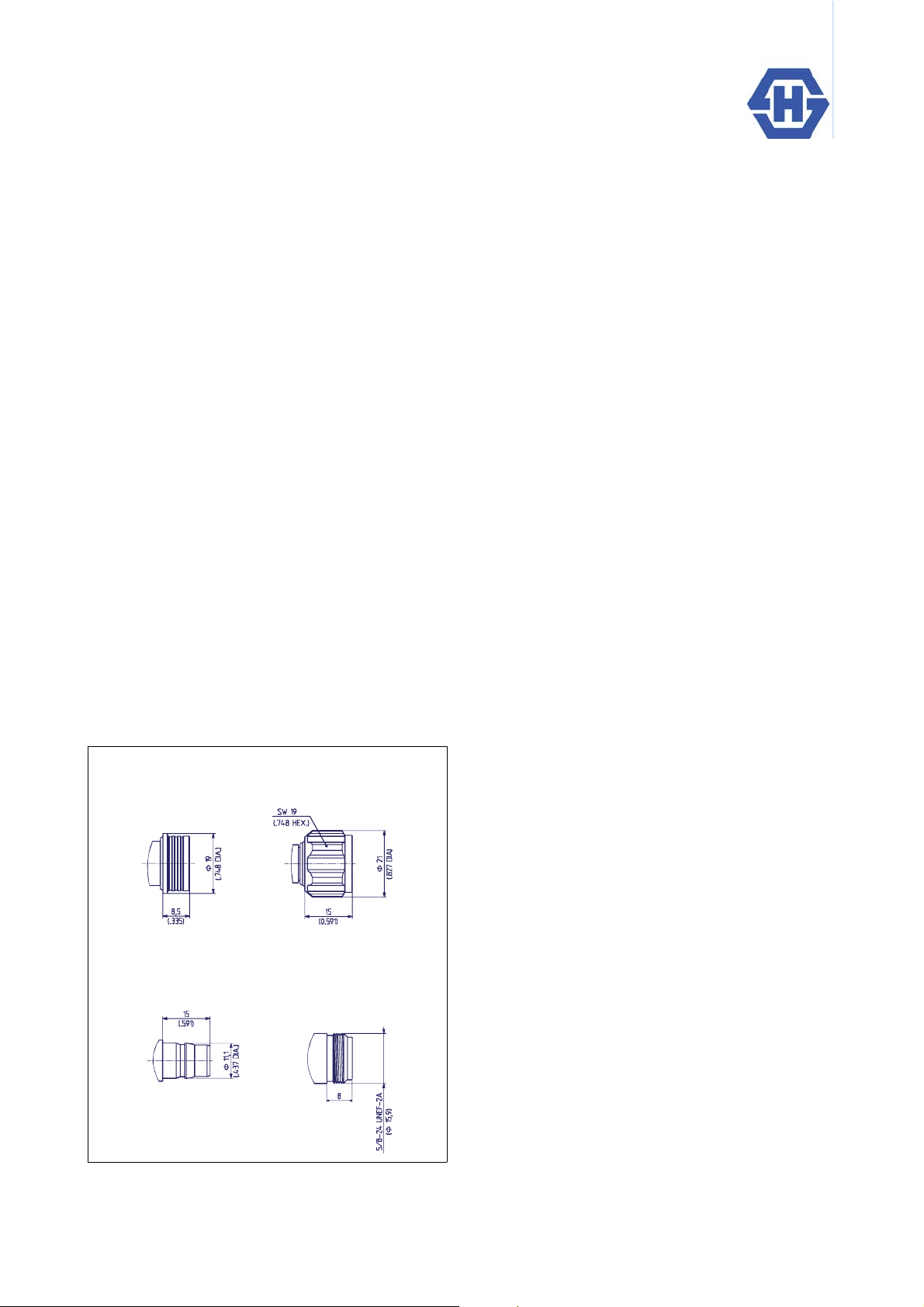
INTERFACE DIMENSIONS (COMPARED TO N)
Plug (male)
QN N
Jack (female)
QN N
FEATURES OF QN CONNECTORS
> Cycle time improvement for making RF connections
(10 times faster to mount than threaded connectors)
>Notorquerequired
> Higher packaging density
> Free-rotating connection when mated
> Eliminates loosening problems associated with
threaded connectors
> Same performance as N
> Best intermodulation performance thanks to the
unique inter face design
HUBER+SUHNER QN - the cost effective
solution for advanced RF interconnections !
IP rating (interface, mated) IP68
QN
191HUBER+SUHNER£QN – a QLF connector
Page 2
TECHNICAL DATA
ELECTRICAL DATA
Impedance 50 8
Frequency range DC to 6 GHz (optimized) DC to 11 GHz (working range)
Dielectric withstanding voltage
(at sea level, in V rms, 50 Hz))
Wor king volta ge
(at sea level, in V rms, 50 Hz)
Insulation resistance 5 ¡ 103M8
Contact resistance
- centre contact
-outercontact
RF-leakage 100MHzto3GHz –90 dB
Return loss (typical) DC–3GHz 32 dB; 3 to 6 GHz 25 dB; 6 to 11 GHz 20 dB
Intermodulation better–155dBc(2x43dBmcarrier)
MECHANICAL DATA
Durability (matings) t 100
Engagement force (typical) 30 N
Disengagement force (typical) 30 N
Retention force for interface t 450 N
Bending moment admissible (interface) d 10 Nm
Contact captivation t 28 N
1) Value considers maximum load of the cables without irreversible variations of specifications.
REQUIREMENTS
2500
$1000
$ 1.5 m8
$ 1.5 m8
REQUIREMENTS
ENVIRONMENTAL DATA
Temperature range – 40qC ... + 125qC/–40qF ... + 257qF
Climatic category 40 / 125 / 21 (IEC 60169_1 16.2)
Moisture resistance MIL–STD–202 F, Method 106 F
Corrosion Saltspray test acc. to MIL-STD-202 F, Method 101 D, Condition B
Vibration IEC-1169-1 paragraph 9.3.3. (10-500 Hz; 5g)
Shock MIL-STD-202 F, Method 213, Condition I
Rapid change of temperature IEC 60169-1 16.4 ( –40q C ... + 125q C/–40qF ... + 257qF )
TEST CONDITIONS
192 HUBER+SUHNER£QN – a QLF connector
Page 3
MATERIAL DATA
CONNECTOR PART MATERIAL PLATING
Bodies brass SUCOPLATE
Pin contacts brass SUCOPRO
Socket contacts spring bronze SUCOPRO
Insulators typ.: PTFE or PFA
Contact washer spring bronze or copper beryllium SUCOPRO
£
Some connectors may have a specification that differs from the above mentioned data.
The products are designed and guaranteed to pass the above mentioned test procedures. Any
additional or different requirement arising from specific applications or environmental conditions
which is not covered by these test procedures is subject to request.
QN
193HUBER+SUHNER£QN – a QLF connector
Page 4

CABLE CONNECTORS
Straight cable plugs (male)
> for semi-rigid cables, SUCOFORM and MULTIFLEX cables
> cable entry soldered
> centre contact plugged-in
Assembly
HUBER+SUHNER type Item no. Cable group (example) Packaging
11_QN -50-3-3/113_NE 23033393 Y5 , Y12 (SM 141 ) single 27502
>forflexiblecables
£
> HUBER+SUHNER
full crimp
instruction
Notes
Assembly
HUBER+SUHNER type Item no. Cable group (example) Packaging
11_QN -50-3-1/133_NE 23033391 U9 (EF 142) single 27500 2B
11_QN -50-3-2/133_NE 23033392 U7 (RG 58 C/U) single 27501 2B
instruction
Crimp insert
>forflexiblecables
£
> HUBER+SUHNER
HUBER+SUHNER type Item no. Cable group (example) Packaging
11_QN -50-7-1/133_NE 23033394 U32 (RG 21 4/U) single 27503 3D
11_QN -50-7-2/133_NE 23033395 U33 (EF 393) single 27504 2.5D
11_QN -50-7-3/133_NE 23033396 U2 9 ( R G 213/U) single 27505 3D
full crimp
Assembly
instruction
Crimp insert
Cable groups see page 28 Assembly tools see page 385 Mounting holes see page 412
194 HUBER+SUHNER£QN – a QLF connector
Page 5

Right angle cable plugs (male)
> for semi-rigid cables, SUCOFORM and MULTIFLEX cables
> cable entry soldered
> centre contact soldered
Assembly
HUBER+SUHNER type Item no. Cable group (example) Packaging
16_QN -50-3-3/13-_ NE 23033268 Y5 , Y12 (SM 141 ) single 27508
>forflexiblecables
> cable entry crimp
> centre contact soldered
instruction
Notes
Assembly
HUBER+SUHNER type Item no. Cable group (example) Packaging
16_QN-50-3-1/133_NE 23033267 U11 (EF 400) single 27506 B
16_QN-50-3-2/133_NE 23033398 U7 (RG 58 C/U) single 27507 B
16_QN-50-4-1/133_NE 23033078 S16 (S 04262 D) single 27509 C
instruction
>forflexiblecables
> cable entry crimp
> centre contact soldered
Assembly
HUBER+SUHNER type Item no. Cable group (example) Packaging
16_QN-50-7-1/133_NE 23032410 U32,U33 (EF 393) single 27510 D
16_QN-50-7-2/133_NE 23033399 U2 9 ( R G 213/U) single 27511 D
instruction
QN
Crimp insert
Crimp insert
Cable groups see page 28 Assembly tools see page 385 Mounting holes see page 412
195HUBER+SUHNER£QN – a QLF connector
Page 6

Straight bulkhead cable jacks (female)
> for semi-rigid cables, SUCOFORM and MULTIFLEX cables
> cable entry soldered
> centre contact plugged-in
Assembly
HUBER+SUHNER type Item no. Cable group (example) Packaging
24_QN-50-3-3/13-_NE 23033423 Y 5 , Y 12 (S M 141) single 27514 ML 112
>forflexiblecables
£
> HUBER+SUHNER
full crimp
instruction
Mounting hole
Assembly instruction/
HUBER+SUHNER type Item no. Cable group (example) Packaging
24_QN-50-3-1/133_NE 23033400 U9 (EF 142) single 27512 / ML 11 2 2B
24_QN-50-3-2/133_NE 23033402 U7 (RG 58 C/U) single 27513 / ML 11 2 2B
Mounting hole
Crimp insert
>forflexiblecables
£
> HUBER+SUHNER
HUBER+SUHNER type Item no. Cable group (example) Packaging
24_QN-50-7-1/133_NE 23033403 U33 (EF 393) single 27515 / ML 112 2.5D
24_QN-50-7-2/133_NE 23033404 U32 (RG 214/U) single 27516 / ML 11 2 3D
24_QN-50-7-3/133_NE 23033405 U2 9 ( R G 213/U) single 27517 / ML 112 3D
full crimp
Assembly instruction/
Mounting hole
Crimp insert
Cable groups see page 28 Assembly tools see page 385 Mounting holes see page 412
196 HUBER+SUHNER£QN – a QLF connector
Page 7

RECEPTACLES WITH SOLDER END
Receptacles, jacks (female)
> bulkhead mounted
> press-in chassis mount
HUBER+SUHNER type Item no. Packaging Notes
22_QN-50-0-1/133_NE 23033237 single press -in
22_QN-50-0-1/133_NY 23033904 bulk 100 pcs. press-in
> panel mounted
HUBER+SUHNER type Item no. Packaging Notes
23_QN-50-0-1/133_NE 23033251 single flange with same dimensions as TNC
23_QN-50-0-1/133_NY 23033252 bulk 100 pcs. flange with same dimensions as TNC
QN
Cable groups see page 28 Assembly tools see page 385 Mounting holes see page 412
197HUBER+SUHNER£QN – a QLF connector
Page 8

QN-CALIBRATION WITH ADAPTOR SWAPPING METHOD
For return Loss/VSWR measurement of QN connectors, HUBER+SUHNER recommends the following calibration
method:
1. Calibration with PC7 to PC7 calibration adaptors (PC7calibration)
Adaptors: 32_PC7-U50-0-1/1--_NE (Item no. 23032719) and
33_PC7-U50-0-1/1--_NE (Item no. 23032721)
Calibration Kit
for PC7
to NWA calibration adaptor calibration adaptor to NWA
Alternative calibration with N to PC7 calibration adaptors (N calibration)
Adaptors: 32_N-PC7-50-6/1--_NE (Item no. 23032917) see page 373 or
33_PC7-N-50-6/1--_NE (Item no. 23032916) see page 374
Calibration Kit
for N
to NWA calibration adaptor calibration adaptor to NWA
2. Exchanging of the calibration adaptors with the required QN adaptors
32_PC7-QN-50-1/1--_NE (Item no. 23032720) see page 377 or
33_PC7-QN-50-1/1--_NE (Item no. 23032722) see page 377
DUT
Thanks to the same electrical length and the same return loss behaviour of all these adaptors, the adaptor swapping
method can be used (same dimensions of all electrical relevant piece parts in these adaptors).
Cable groups see page 28 Assembly tools see page 385 Mounting holes see page 412
198 HUBER+SUHNER£QN – a QLF connector
 Loading...