

Huber K12-cc-NR, K6-cc, K20-cc-NR, K25-cc-NR, K6s-cc-NR Operating Manual
...
Operating manual
CC
27.09.2011
Also for models with natural refrigerants
Valid for:
K12-cc-NR, K15-cc-NR, K20-cc-NR, K25-cc-NR, K6-cc, K6s-cc-NR
variostat cc
ministat 125-cc, ministat 125w-cc
ministat 230-cc, ministat 230w-cc
ministat 240-cc, ministat 240w-cc
CC-405, CC-405w, CC-410wl, CC-415, CC-415wl
CC-505, CC-505wl, CC508, CC-510, CC-510w, CC-515, CC-515w
CC-520w, CC-525w
CC-805, CC-820, CC-820w, CC902, CC-905, CC-905w, CC-906w

2
Contents V2.2/09.11 // software V06.10.001
Foreword ............................................................................................................4
Quick guide for CC-thermostats.............................................................................5
Chapter 1: Safety ................................................................................................7
Description of Safety and Information symbols ........................................................ 8
Intended Use and General Safety Instructions..........................................................9
Description .......................................................................................................10
Duties of responsible person ...............................................................................11
Operator requirements........................................................................................ 11
Machine operator duties .....................................................................................11
Work area......................................................................................................... 11
Safety Devices to DIN12876...............................................................................12
Additional Protection Devices .............................................................................. 14
Environmental Conditions.................................................................................... 14
Operating conditions .......................................................................................... 15
Location ...........................................................................................................16
Thermal fluids ...................................................................................................17
Chapter 2: Electronics and operation .................................................................... 18
CC-Pilot............................................................................................................ 19
Information Displays CC .....................................................................................20
Real-time clock .................................................................................................. 23
Rechargeable Battery ...................................................................................... 23
Event Function ............................................................................................... 23
Operation CC ....................................................................................................24
CC Operation using the rotary knob ..................................................................... 25
CC Operation using the simulated Number Pad ......................................................26
Main menu........................................................................................................27
Compact menu .................................................................................................. 28
Comfort menu ................................................................................................... 36
Com.G@te menu ............................................................................................... 43
Function Numbers and their meaning....................................................................50
User menu – config............................................................................................ 56
User menu - select ............................................................................................. 57
Chapter 3: Connect the machine, fill and prepare for the required application ............58
Power connection .............................................................................................. 59
Safety instructions............................................................................................. 59
Start up............................................................................................................ 59
Freeze protection (only valid for temperature control units with the option Freeze
Protection) ........................................................................................................ 59
Water-cooling (valid for units with water cooling) .................................................. 60
Operation as bath thermostat (valid for temperature control units with baths)............ 61
Connecting an externally closed application (reactor).............................................. 62
Switching on the temperature control unit ............................................................ 63
Setting the over-temperature (OT) switch .............................................................63
Setting the set-point limits .................................................................................. 66
Entering a set-point ............................................................................................ 66
Starting CC Temperature control.......................................................................... 66

3
Ending CC Temperature control ...........................................................................67
Filling and air purging an externally closed system ................................................. 68
Draining the machine and an externally closed application....................................... 69
Changing thermal fluid / internal cleaning .............................................................. 69
Chapter 4: Interfaces ......................................................................................... 70
Interface modules (RS232/SERIAL, Com.G@te and Web.G@te) and Interface menus . 71
RS232/SERIAL .................................................................................................. 73
Mutual functions Com.G@te/Web.G@te............................................................... 74
Specific functions Com.G@te..............................................................................76
Specific functions Web.G@te.............................................................................. 77
Chapter 5: First aid for a fault condition................................................................ 82
Messages .........................................................................................................83
Display Error Messages....................................................................................... 84
Alarms and Warnings ......................................................................................84
System Messages........................................................................................... 84
Alarm and Warning codes ................................................................................... 85
Hard Alarms (not resettable)............................................................................. 85
Exchange of the CC Electronics / Remote Control ..................................................88
Remote Control: .............................................................................................88
Maintenance .....................................................................................................89
Decontamination / Repair .................................................................................... 90
Cleaning the surfaces ......................................................................................... 90
Plug contacts ....................................................................................................90
Chapter 6: Taking the machine out of service........................................................ 91
Decommissioning...............................................................................................92
Transport..........................................................................................................93
Disposal ...........................................................................................................93
Appendix

4
Foreword
Dear Customer,
The Huber team would like to thank you for ordering this product. You have made a
good choice. We thank you for your trust!
Please read and understand the instruction manual thoroughly before operating the unit.
All instructions and safety information must be complied with.
Please read this manual before transporting, commissioning, operating, maintaining,
repairing, storing or disposing of this unit.
Failure to comply with the instructions within this manual may invalidate any warranty
for this unit.
5
Quick guide for CC-thermostats
Checklist for initial operation:
1. Make sure that the machine is connected correctly and enough thermal fluid is
inside.
2. Switch on the unit via the mains switch!
3. Make sure that the over-temperature is set correctly.
4. Make sure that the set-point limits (min and max) are set correctly.
5. Enter e.g. a new set-point!
6. Make sure that you have set the correct temperature control mode (e.g.process)!
7. Start temperature control!
Operation:
Setting the over-temperature protection:
1. Select the function over-temperature from the compact menu!
2. Select the menu point, setting the over-temperature protection!
3. To adjust the over-temperature a code is being given out via the display for
several seconds.
4. You are being requested to enter a code!
5. Enter the code which has been displayed previously!
6. The over-temperature can be adjusted if the code has been entered correctly!
7. The new over-temperature value will be now displayed!
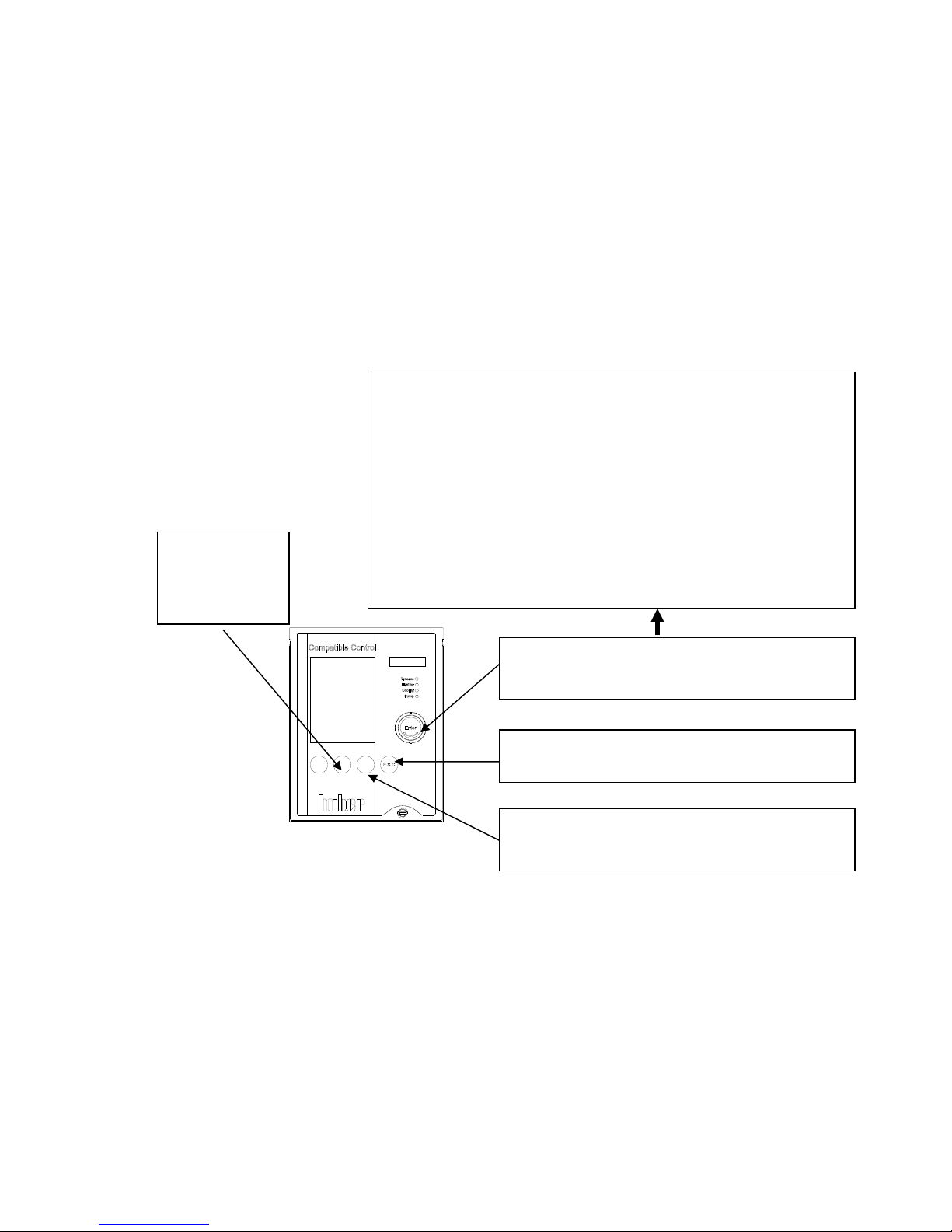
Button for main menu and menu selection.
By pressing the rotary knob / encoder you can reach the
compact menu with above mentioned functions.
T-set button
Press this button to
enter a new setpoint.
ESCAPE-Button
To cancel a process (entry), press the ESC button.
START / STOP-Button
Here you can start / stop circulation, air-purge and
thermoregulation.
Compact menu:
Display modes Here you can select the graphic display.
Comfort menu Here one can have displayed the whole menu function.
Program edit Here you can edit a temperature program.
Program start & stop Here you can start / stop a temperature program.
Pump settings Here you can predefine a pump speed.
Start ramp Here you can predefine a temperature ramp.
Control parameters Here you can select/predefine control parameters.
Set-point Here you can predefine a set-point.
Set-point limits Here you can set set-point limits.
Start&Stop Here you can start / stop temperature control.
Temperature control mode Here you can select between jacket / process control
Over-temp. Protection Here you can set the over-temperature protection.
Select user menu Here you can select an individual menu.
Exit
6
COM.G@TE allocation and setting (quick guide)
1
2
3
6
5
4
3
2
1
3
2
1
1
5
96
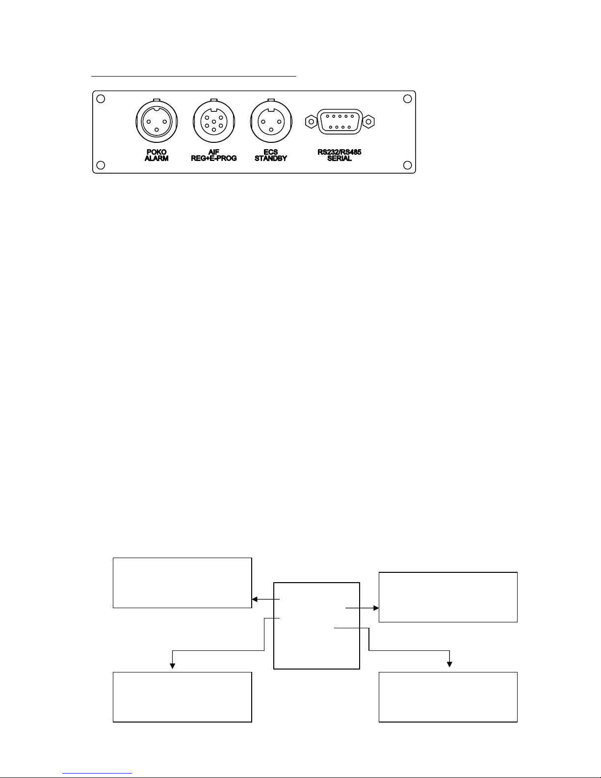
POCO (potential free contact) Alarm plug-in connector
Signal contact for external monitoring.
The connection is designed as a potential free changeover contact.
Normally open contact between pin 1 and pin 2. Normally closed contact between pin 2 and pin 3.
Contact load: 1A at 24V DC Only use screened lines!
AIF Reg-E-Prog Socket
Analogue interface, one input channel (programmable) and 3 output channels.
Pin Signal
1. Current output, T extern 0/4-20mA or 0-10V
2. Current output, set-point 0/4-20mA or 0-10V
3. GND for analogue outputs GND
4. Analogue input (programmable) 0/4-20mA or 0-10V
5. Current output, free programmable 0/4-20mA or 0-10V
6. GND for analogue input GND
ECS Socket (External Control Signal) Standby
Release signal ECS (External Control Signal), for starting / stopping temperature control.
The following variants are offered:
Pin Signal
1,3 E2
2 E1
RS232 / RS485 Serial Socket
Wiring RS232: Wiring RS485
Pin2 RxD Receive Data Pin6 A with 120 Ohm load resistance
Pin3 TxD Transmit Data Pin7 A
Pin5 GND Signal GND Pin8 B
Functions in connection with PLS
Settings for analogue interface, release signal, signal contact and digital interface RS232 / RS485 can be made via the
functions Analogue Interface, RS232 / RS485, ECS Standby and POCO Alarm in the COM.G@TE menu.
Standard settings are:
Analogue interface: analogue input OFF and analogue output OFF
RS232 / RS485: RS232 with Baudrate 9600
ECS Standby: no action
POCO Alarm: no alarm
Here you can determine e.g. the
dig. Interface, as well as baudrate
and slave address with RS485!
Here you can determine whether
the unit reports a contact condition
in case of a disturbance (alarm).
Here you can determine a
temperature / current range and
predefine the current input value as
set-point or speed of rotation!
Here you can determine whether
the temperature control unit is
switched OFF/ON via an external
switch contact!
COM.G@TE:
Analogue-Interface
RS232/RS485
ECS Standby
POCO Alarm
Return to main m...

7
Chapter 1: Safety
In this chapter is to be found the following sections:
- Description of safety and information symbols
- Intended use and General Safety Information
- Description
- Duties of the responsible person
- Operator requirements
- Machine operator duties
- Work area
- Safety Devices to DIN 12876 (applicable for units with heating)
- Additional Protection Devices (if provided)
- Environmental conditions
- Operating conditions
- Location
- Thermal fluids
8
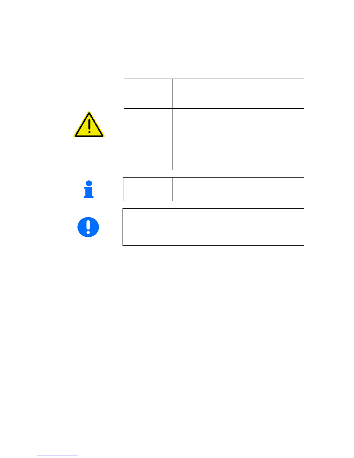
Description of Safety and Information symbols
Safety information is shown with a pictogram and keyword.
The keyword indicates the level of the corresponding danger.
Danger!
Immediate risk to the life and health of
personnel (Serious injury or death).
Warning!
Possible risk to the life and health of
personnel (Serious injury or death).
Caution!
Possible dangerous situation (possible injury
to personnel or damage to property).
Information!
User-tips and other useful information.
Requirement!
Requirement to carry out a specific
method, or action, for safe machine
operation.

9
Intended Use and General Safety Instructions
Danger!
Non-intended use can result in considerable personal injuries and material damage.
No third persons are authorized to make any changes to the machine. The device
declaration becomes void, if any modification is carried out without manufacturers
consent. Only personnel trained by the manufacturer may carry out modifications,
repairs or maintenance work.
The following must be observed:
Always use the machine in a perfect working condition!
Only expert personnel may initially start-up and repair the device!
Do not bypass, bridge-over, dismantle or switch off the safety mechanisms!
The manufacturer is not liable for damages caused by technical changes
to the temperature control device, inappropriate handling and / or use of the
temperature control device without regard to the operating instructions.
The temperature control device is manufactured for commercial use only and may only
be used to maintain the temperature within the internal bath (does not apply for chillers)
and to maintain the temperature of reactors or other professionally expedient objects in
laboratories and industry. Suitable thermal fluids are used throughout the entire system.
The cooling or heating power is provided at the pump connections and in the bath itself
(does not apply for chillers). The technical specifications of the temperature control
device are determined in the data sheet. Operation must be prepared and carried out
according to the operating instructions. Any non-observance of the operating
instructions is considered as non-intended use.
The temperature control device corresponds to the state-of-the-art and the recognized
safety-related regulations. Safety devices are built into your temperature control device.
The device is NOT approved for use as a medical product!
This temperature control unit is NOT built as explosion-proof and is NOT
suitable for use in "ATEX" areas!
Foreseeable non-intended use:
- Activate the brakes for machines with rollers or roller support.

10
Description
These temperature control machines have been designed to be used with either external
closed systems (e.g. jacketed reactors) or the internal bath.
For temperature control devices with compressor cooling, the low internal volume
combined with high performance refrigeration and heating technology, gives a very
short cooling and heating time compared with conventional bath technology.
With the integrated speed controlled pump fitted in the table models and some floor
standing models, it is possible to control flow and / or pressure of the thermal fluid and
thus can be exactly adapted for the required application.
With help of the self optimising cascade controller, you obtain the optimum control
results under steady state conditions as well as by set point changes and with
exothermic reactions. One can choose between aperiodic or with a small overswing
(faster) control.
Information and temperature development can be easily read via the large graphic
display screen (with touch screen) as well as give command inputs.
A comfortable menu guidance eases the operation of the machine. The software
package Basic, Exclusive and Professional offer high functionality and comfort in usage
for users with simple temperature control tasks up to demanding temperature control
tasks. For a small extra charge the functionality can be extended by E-Grade. Here you
have the possibility to upgrade your package from Basic to Professional via an
activation key (please contact our Customer Support).
The optional Com.G@te with the digital interfaces RS232, RS485, the analogue 0/4-
20mA or 0-10V interface as well as various digital in and output possibilities (all
according to the NAMUR), and fitted as standard, the machine (valid for Basic,
Exclusive and Professional) can be fitted without problem into many laboratory
automation systems.
The removable CC-Pilot can be used as a remote control.
External temperature control requirements can be easily met (requirement E-Grade
Exclusive or Professional) via the external Pt100 connection (NAMUR standard).
The integrated temperature-ramp function as well as the internal programmer
underline
the high level of operator comfort. The integrated programmer offers the possibility of 3
different temperature programs each with 5 program steps (E-Grade Exclusive) or 10
different temperature programs with a maximum of 100 steps (E-Grade Professional),
which can be made and then called up.
The thermostat uses an over-temperature protection in accordance with DIN EN 61010-
2-010, which is independent of the actual control circuits.

11
Duties of responsible person
The operating instruction is to be kept easily accessible and in immediate vicinity of the
unit. Only suitably qualified personnel should operate this unit. Personnel should be
properly trained before operating the unit. Make sure that the operators have read and
understood the instruction manual. Supply appropriate Personal Protective Equipment as
required.
Operator requirements
Only authorised personnel should operate this unit. Personnel should be properly trained
before operating the unit. The minimum age for operators is 18 years. Personnel under
18 years should only operate the unit under the direct supervision of qualified
personnel. The operator is responsible for third parties within the working area.
Machine operator duties
Make sure that the operators have read and understood the instruction manual. Please
observe the safety instructions. Appropriate Personal Protective Equipment (e.g. safety
goggles, safety gloves) should be worn when operating the unit.
Work area
Work area is defined as the area in front of the machines control panel. Work area is
determined by the peripheral equipment connected by the operator.
It is the customer’s responsibility to ensure a clear, safe working area around the
temperature control unit. The arrangement of the work area should be made after
considering access to, and risk assessment of, the area and application.

12
Safety Devices to DIN12876
- Low-liquid level protection
- Adjustable over-temperature protection
Table 2 – Classification of laboratory circulators and laboratory baths
Class
designation
Heat transfer
liquid
Technical requirement Marking
d
I non-flammable
a
overheating protection c NFL
II adjustable overheating protection
flammable b FL
III
adjustable over-temperature
protection and additional low-liquid
level protection
a
Usually water; other liquids only if they are non-flammable within the temperature range
in single fault condition
b
Bath liquids shall have a flash point ≥ 65 °C, this means if ethanol is used, only
supervised operation is possible.
c
Overheating protection can be by using for example a suitable liquid level sensor or
a suitable temperature limiting device.
d
Optional at the manufacturer`s discretion.
Your temperature control unit is designated a Class III FL.
The type and function of the over-temperature protection and low-level protection is
dependent on the temperature control unit.
Monitoring of the over-temperature is the same for all CC-Thermostats. As, there are
models with two sensors and models with only one sensor.
Two diferent types of low-level protection are available (depending on the model):
1. Temperature control machines with classical float (e.g. ministats)
2. Temperature control machines with an electronic low-level protection (e.g. K6-
cc-NR)

13
To 1. Temperature control machines with classcial float
The most common and known type of level monitoring is the mechanical float. The float
swims on the surface of the thermal fluid in the bath, and leads to a switching system.
Depending on the level of the thermal fluid, the electronics will either signalize an OK
state (with sufficient filling of the thermal fluid) or a non OK state (with insufficient
filling of the thermal fluid). The float system function should be checked from time to
time. In order to do this, whilst in standby mode, push the float in the bath downwards
with a tool (e.g. screw driver). The electronics should then trigger an alarm.
To 2. Temperature control machines with electronical low-level protection (ELO)
ELO: Electronic over-temperature and low-level protection in combination
Some temperature control machines (depending on the model) possess an electronic
over-temperature and low-level protection. Instead of a mechanical float switch
temperature sensors are mounted on the surface of the heating coils to monitor the
over-temperature at a potential ignition source and to ensure that the critical
temperature at the heating coils (burn point of the thermal fluid) is controlled by the
controller (not valid for chillers, liquid level is determined by electrical capacity) via the
graphical display (60) error message will be given out.
A mechanical tool is no longer required to change the over-temperature settings. The
over-temperature switch can only be adjusted after the user has re-entered a code
displayed on the CC-Pilot´s display (60). This procedure avoids unintentional changes
being made to the setting and replaces a mechanical tool by software.
A new feature is the Process Safety function. This function provides further protection
for the operators and application. A classic over-temperature device unit would trip and
cause a shutdown if over-temperature cut-off temperature was reached. This could
occur under circumstances where more heat was being generated by a process
(exothermic) than the unit could remove. Switching the temperature control unit off
would remove the only possible method of cooling the application down. Consequently,
the temperature would be able to further increase, creating a risk of injury to personnel
or damage to the application, for example by over-heating a liquid into pressurised
vapour.
Using the Process Safety function, the controller recognises when the over-temperature
cut-off is reached, and switches the cooling on. The compressor automatic is
automatically set to always on. Even if the temperature continues to rise, the
refrigeration machine will increase its cooling to maximum to minimise the heating.
Please also note chapter on Setting the over-temperature (OT) switch.

14
Additional Protection Devices
- Auto-Start function
- Alarm function
- Warning messages
- General unit messages
Danger!
Emergency Procedure: Disconnect Electrical Power!
Turn the Mains isolator (36) to “0”!
Dangerous liquid / vapours from temperature control unit or connected hoses (very hot,
very cold, dangerous chemicals) and / or fire / explosion / implosion:
Evacuate the area, following local regulations and procedures to prevent injury or loss
of life! Refer to the MSDS Safety information for the thermal fluid concerned!
Environmental Conditions
This unit, and operations, will comply with DIN EN 61010-1:2001, only when it is
located in suitable environmental conditions.
- for indoor use only;
- installation site ≤ 2000 m altitude;
- installed on a level, even, non flammable surface;
- maintain a clearance above and around the unit of 10 cm for water-cooled units,
and 20cm for air-cooled units, to allow air to circulate around the unit;
- for ambient temperature conditions please refer to the technical data sheet;
remaining within these ambient conditions is imperative in ensuring accurate
operation;
- maximum relative humidity of 80% up to 32°C, decreasing linearly to 50%
relative humidity at 40°C
- use only as long a power cord as necessary;
- the unit should be located so as not to restrict access to the mains power
switch;
- mains voltage should be ±10% of the rated value;
- avoid voltage spikes;
- transient voltage surges as they occur normally in the supply grid;
- clean rating 2;
- overvoltage category II

15
Operating conditions
Please make sure that the application and system performance is dependent upon the
temperature range, viscosity, and flow rate of the thermal fluid:
- Please ensure that the power supply connections are correctly dimensioned.
- The temperature control device should be located so, that sufficient fresh air
is available even when working with water cooled units.
- Please note that hose connections should be compatible with the thermal
fluid used and the working conditions.
- When choosing the thermal fluid, not only minimal and maximum
temperatures have to be complied with but also have to be suitable regarding
burn point, viscosity and / or freezing. Furthermore the thermal fluid has to be
compatible with all the materials used in the unit.
- Pressure changes with the length of hoses (keep as short as possible).
Choose as large a diameter of hoses as possible (the width of the pump
connections are considered as a point of reference) and may negatively affect
temperature control results. Flow restrictions may occur if a too narrow
connector is selected for corrugated hoses.
- The use of unsuitable hoses or hose connections may cause thermal and
toxic injury to personal and environment. Temperature control hoses and their
connections have to be insulated / secured against contact / mechanical
damage.
- Non-suitable thermal fluids can negatively affect temperature control and be
the cause of negative temperature results and damages. Therefore only use
the thermal fluids recommended by the manufacturer and only in the intended
temperature and pressure range. The application should be located on
approximately the same level or lower than the temperature control device, if
temperature control is to be carried out near to the boiling temperature of the
thermal fluid. The thermal fluid should have room temperature when filling.
Fill in the thermal fluid slowly, carefully and steadily. At the same time make
sure that no thermal fluid overflows (back pressure); it is thereby necessary
to wear personal protective equipment, e.g. safety goggles, thermally and
chemically resistant gloves, etc.
- After filling and setting all necessary parameters the thermoregulation circuit
has to be degassed. This is a requirement for proper operation of the device
and thus its application.
- In the case of pressure-sensitive applications, e.g. glass reactors, observe the
maximum inlet pressure of the temperature control device for cross section
reduction or shut-off (see data sheet). Take suitable precautions (e.g.
pressure limitation for temperature control devices with pressure control,
bypass).
- In order to avoid danger of overpressure in the system, which could damage
the temperature control device or the application, the thermal fluid must
always be adapted at room temperature before turning off and a possibly
available shut-off valve must be left open (pressure compensation).
- Temperature and dynamics within the reactor are determined by the outlet
temperature. A differential temperature is created (delta T) between outlet
temperature and the temperature within the reactor. This difference in

16
temperature has to be adapted, depending upon type of glass application. As
the differential temperature may exceed the admissible limit values and bursts
may occur. Delta T value has to be adapted to the corresponding application.
Therefore please see chapter Comfort menu.
- Do not kink the hoses.
- Check hoses in regular intervals for material fatigue (e.g. cracks).
With water cooled units please pay special attention to the maximum operating
temperature and differential pressure requirements for the cooling water. Therefore
please refer to the technical data sheet.
Danger!
If the cooling water contains high levels of minerals, e.g. chloride, bromide then suitable
water treatment chemicals should be used. Use only recommended materials to
maintain the unit warranty. Further information on corrosion, (appearance and
avoidance) can be found on our website www.huber-online.com
under "Download /
Safety data sheets thermal fluids / Characteristics of water".
Please refer to the sections on Intended use and general safety instructions.
Location
Caution!
- Transport the unit upright
- The unit should be mounted in an upright and secure position, on a solid, stable
surface
- Place on a non flammable surface
- Keep the area around the unit clean, to avoid slip and trip hazards
- Set the brakes on the castors once the unit is in position
- Place suitable absorbent material under the unit to catch any condensate and
thermal fluid spills
- Any spillage of thermal fluid should be immediately cleaned up
- For large units, check the weight / load capacity for the flooring

17
Thermal fluids
We recommend the thermal fluid shown in our catalogue. The name of a thermal fluid is
derived from the working temperature range and the viscosity at 25 °C.
Examples of thermal fluids in our catalogue:
M40.165.10:
Lower working limit -40 °C
Upper working limit 165 °C
Viscosity at 25 °C: 10 mm
2
/s
The data sheet for the thermal fluid used is of utmost importance, and must be read
before use. This data sheet should be followed.
Please note the classification of your machine according to DIN 12876
The chosen thermal fluid must be compatible with stainless steel 1.4301 (V2A)
and FKM!
The maximum viscosity of the thermal fluid may not exceed 50 mm²/s at the
lowest temperature reached!
The maximum density of the thermal fluid may not exceed 1kg / dm³
For chillers we recommend as thermal fluid a mixture of water and glycol (a
mixture is recommended that permits a temperature down to -25°C).
Information on water quality can be found on our website (www.huber-
online.com) under "Download / Safety data sheets thermal fluids /
Characteristics of water".

18
Chapter 2: Electronics and operation
The following sections are to be found in this chapter:
- CC-Pilot
- Information display
- Real time clock
- Operation
- Operation using the rotary knob
- Operation using the simulated Number Pad
- Main menu points
- Compact menu
- Comfort menu
- Com.G@te menu
- Function numbers and their meaning
- Configure user menus
- Select user menus
19
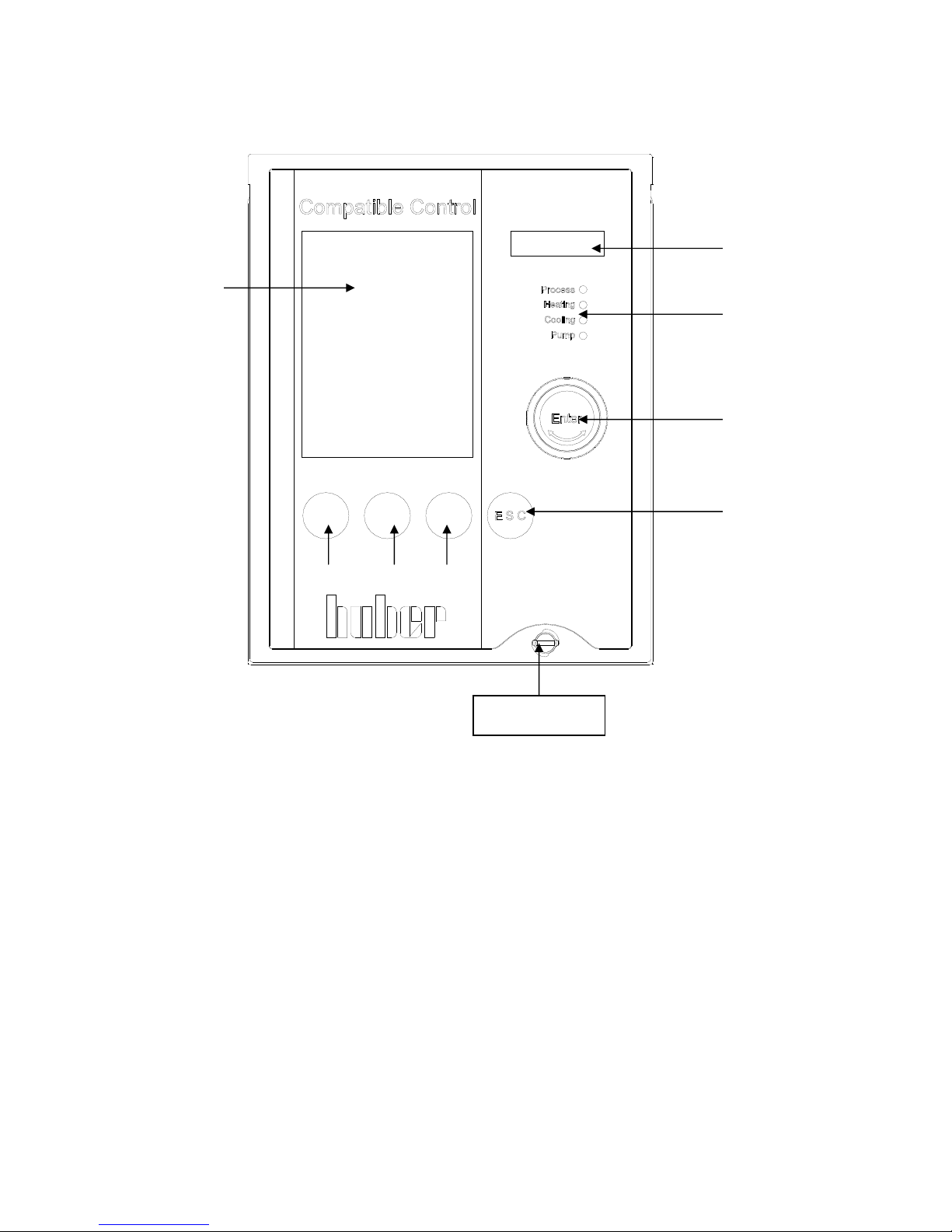
CC-Pilot
60) Touch screen and graphic display
61) Key and rotary knob
62) ESC key
63) Key 1 (Soft-key 1)
64) Key 2 (Soft-key 2)
65) Key 3 (Soft-key 3)
66) LED temperature display
68) LED status display
60
66
68
61
62
Locking
63 64 65
20
Information Displays CC
The following information displays are available:
1. Graphical display (60)
The most important display, giving details of standard parameters (set-point, current
temperature, set-point limits), as well as menu options and error messages.
2. LED temperature display (66)
The green LED display shows the current temperature.
Please note that in internal control mode the internal temperature (outlet temperature /
jacket temperature) will be shown, and with cascade control mode the process
temperature (reactor temperature) will be shown.
3. LED status display (68)
Information on the actual operating status of the temperature control unit (e.g.
circulation is active, cooling machine is active, heating is active, process control is
active).
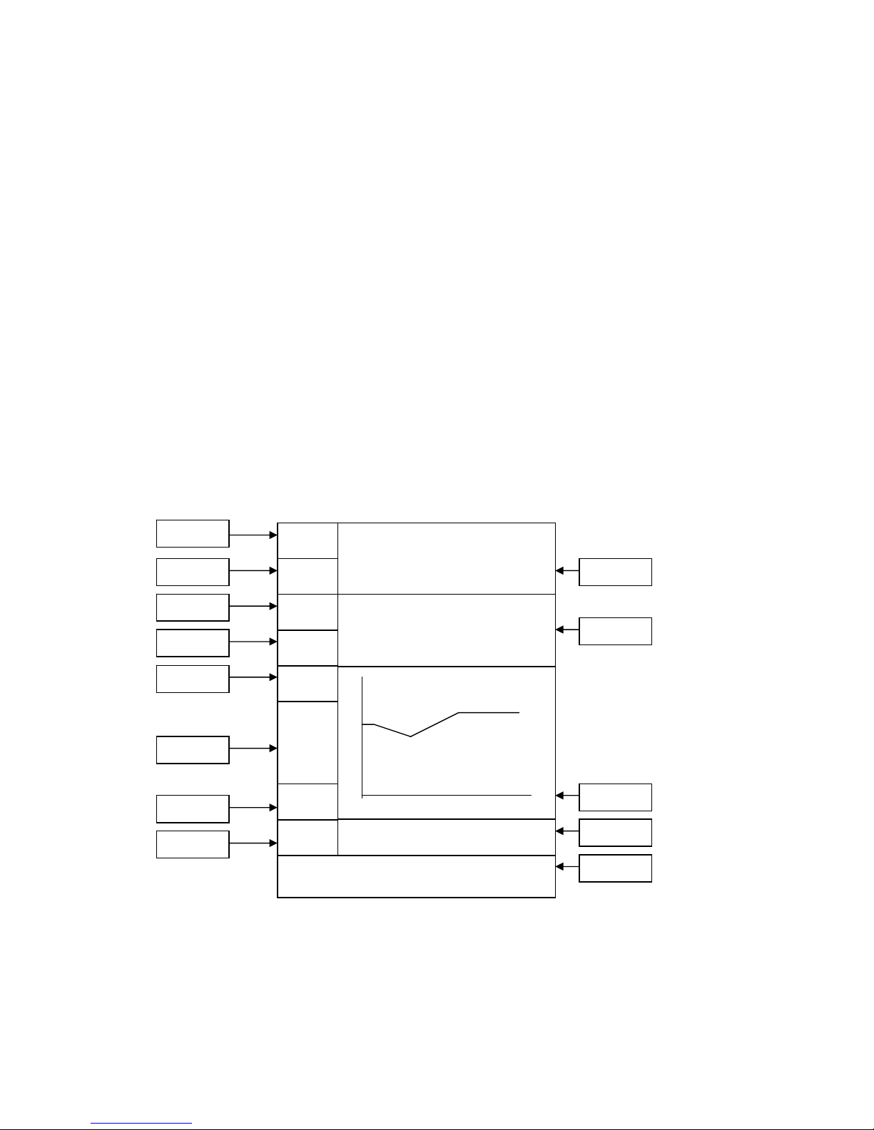
Screen display (this display is reached by selecting Main Menu / Display modes /
Graphic)
Please also note operating options described in chapter operation.
22.04.08
07:35.20
Funct.-no. Tset-point(F0) start
?
Tmin.
-35.0
Tmax.
150.0
delta T
100.0
OT
80.00
T process 20.00
T internal 19.50
T set-point 15.00
Field 13
Field 12
Field 11
Field 10
Field 9
Field 8
Field 7
Field 6
Field 5
Field 4
Field 3
Field 2
Field 1

21
Description of individual Fields
Field 1: Display Current value
This field shows the current internal temperature of the unit and, if an external sensor is
connected, the current process temperature.
Field 2: Display set-point
This field displays the current set-point.
Field 3: Display Graphic temperature
This field shows the internal and process temperatures in graphical format. The span of
the temperature axis is between the minimum (see field 7) and maximum set-point
limits (see also field 10).
Field 4: Display Status Field
This field shows useful information such as the current temperature control mode
(internal or process), unit operations (degassing, air-purging) and active control loops.
Field 5: Display Soft-keys operation
This field enables various functions. Please therefore note the soft keys (63, 64, 65)
located directly under the relevant touch screen buttons. The Function Number menu
can be displayed by lightly touching the soft key 63 Funct.-no area of the screen.
Please refer to the Function Numbers and Definitions chapter for more details.
Pressing the soft key (64) Tset F(0) area of the screen will bring up the option to enter
a new set-point. Pressing the soft key 65 Start of the screen will bring up the Start &
Stop menu. This menu allows the temperature control, air-purging, circulation and
degassing to be started as required. After an operation, the menu will return to the
standard screen. Instead of the function Start in field 5 the function stop is now
available. Pressing the soft key 65 Start of the screen will bring up the Start & Stop
menu again. By pressing the Start area again, any operations previously started may be
stopped.
Field 6: Display Help
Help (general information / trouble-shooting information) will be displayed.
Field 7: Display minimum set-point
This field displays the current minimum set-point limit (corresponds to Funct. no. F1).
The minimum set-point also serves as the lower temperature limit for the graphic
temperature display, in Field 3.
Field 8: Pump and Level information
This field displays the level as well as pump status including pump speed indication
(only for temperature control devices with speed regulation).
Field 9: Display maximum set-point
This field displays the current maximum set-point limit (corresponds to Funct. no. F2).
The minimum set-point also serves as the upper temperature limit for the graphic
temperature display, in Field 3.

22
Field 10: Display delta T
This field displays the delta T value (max. admissible difference between process and
internal temperature). This value may be set within a range of 0…100K under the main
menu point limits / delta T limits. This field is active only with a connected process
sensor and when the temperature control mode process temperature is activated.
Field 11: Display Over-temperature cut-off
This field displays the current setting of the over-temperature cut-off. Please note that
this value can only be changed through the Main menu Over-temperature. Please refer
to the Setting the over-temperature chapter in the Main menu.
Field 12: Display Alarm and Warning messages
This field displays information on any alarm or warning conditions that are present.
Alarm and warning messages are also immediately displayed as text in the graphic
display (60).
Field 13: Display Date and Time
This field displays the current date and time.

23
Real-time clock
Rechargeable Battery
The Unistat Pilot as well as CC-Pilot (for temperature control devices with CC-Pilot) are
equipped with an internal, battery-powered clock that runs even when the unit is turned
off. When the unit is powered up, the actual date and time are uploaded to the unit.
The capacity of the battery means allows the clock to continue to run for a number of
months. If a unit has been powered-down for an extended time, it should be poweredup and left for an hour or so before running it again. If the time and date have been
lost, they can be re-entered during this period.
If after turning off and on again, the time and date have been reset, then it must be
assumed that there is a problem with the rechargeable battery. In this case please
contact our service department.
Event Function
The clock has a programmable event function. Using this function an operation can be
set to run every day (until the function is reset in the operator menu). There are two
available operations:
Acoustic signal: The unit will generate an acoustic signal for about 15 seconds.
Program Start: When configuring the calendar to start a program, the user will be asked
for the number of the program to be started. The program will then be started at the set
time and date, even if (manual) temperature control had not been previously started.

24
Operation CC
Please note, there are multiple possibilities to operate the machine.
1. Operation via function keys T1 to T3 (63, 64, 65), together with information
given in the lowest line of the graphic display (60).
2. Operation via the rotary knob / key (61)
By pressing the key / rotary selector (61) one can choose the individual fields. By
turning the key / rotary selector (61) one can enter directly the input mode.
Leave this mode by pressing the ESC key.
3. Operation via menu points
By pressing the key / rotary selector (61) one enters the main menu. Choose the
function required by turning the key / rotary selector (61). Confirm the input by
pressing the key / rotary selector (61).
The operational possibilities can be used in virtually any combination.
Please note that the procedure presently being chosen can be broken off by using the
ESC-key (62), and one then returns to the display which was selected under Display
modes from the main menu.

25
CC Operation using the rotary knob
Compact menu
Display functions
Comfort menu
Enter program
Program start & stop
Pump settings
Start ramp
Control parameters
Set-point
Set-point limits
Start & stop
Temperature control mode
Over-temperature protection
User menu-select
Once the rotary knob / key (61) has been pressed, the compact menu appears on the
display screen. This menu lists the most commonly used options in alphabetical order.
Turn the rotary knob / key (61) to highlight the required function and then press the
knob to activate that function. An overview of these menu options is given in the Main
menu chapter. Depending on the E-Grade level, an upgrade can be made at any time
with lower and middle levels, and the appropriate menu points will be displayed in the
Graphic display (60). Please contact us at +49(0)781-9603100 or per e-mail under
info@huber-online.com
concerning information regarding upgrades.
26
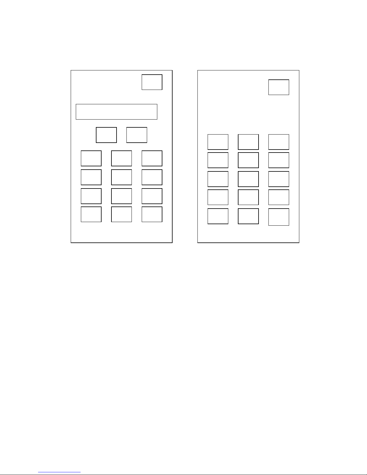
CC Operation using the simulated Number Pad
Function number menu Keyboard
Function number menu:
Pressing the Funct.No. area at the bottom of the graphic display (60) will bring up the
Number pad display. By using the rotary knob /key (61) you may enter the
corresponding number fields, arrow fields, the ESC-Field and the Ok Field. Please note
that the required function number can also be selected by rotating and then pressing
the rotary knob / key (61). Once a valid function number is entered, the function
number and description will appear in the graphic display. The UP / DOWN arrow keys
can be used to step through the function list. Press the OK button to accept the
function, and close the number pad. The functions are going to be displayed in the
graphics display (60) Further description on individual functions are to be found in
chapter Function numbers and their meanings.
Keyboard:
By activating the KEYB Function you may also enter values. This function will be
offered when entering the set-point / set-point limits. Please note that the required
function number can also be selected by rotating and then pressing the rotary knob /
key (61). The selected field will then be highlighted.
1
2 3
4
5 6
7
8 9
ESC
0
OK
^
v
F 0 Set-point
0
Function number
Set-point
New value
_
Maximum value 50.00
Minimum value -20.00
1
2
3
4
5
6
7
8
9
.
0
-
ESC
OK
<-

27
Main menu
The following functions are available:
Compact menu Comfort menu
Control parameters Acoustic alarm
Comfort menu Auto-Start
Display modes Clock
Enter program
Com.G@te (with connected Com.G@te only)
Overtemperature protection Compact menu
Pump settings
Compressor automatic (not valid for all units)
Set-point Control parameters
Set-point limits Display functions
Start & stop Display modes
Start ramp E-Grade packages
Temperature control mode Enter program
User menu - select Factory default
Exit Language
Limits
Overtemperature protection (for units with heating)
Program start&stop
Protection functions
Pump settings
Sensor adjustment
Service
Set-point
Set-point limits
Settings (others)
Software version
Start & stop
Start ramp
Temperature control mode
Temperature scale
Time scale
User menu - config.
User menu - select
2nd set-point
Web.G@te (with connected Web.G@te only)
Exit
The individual functions are described in the following pages:

28
Compact menu
Control parameters: The default setting is Automatic control parameter.
Select auto./ manual
Automatic control parameters
CONTROL PARAMETERS:
Select auto./ manual
Config. automatic
Config. manual param.
Reset control parameters
Display Parameter
Return to main menu
AUTOMATIC CONFIGURATION:
Find control parameters
Control dynamics
Display control parameters
Fluid properties
Go back
Control parameters
KP
Int. 181.3 200,0
TN
Int. 77.6 100,0
TV
Int. 0.0 0.0
CONTROL DYNAMICS:
Fast, small OS
Without overshoot
Go back
SELECT THERMAL FLUID:
No specification
M120.08.02
M90.200.02 (DW-Therm)
M90.055.03 (Sil. oil)
M40.165.10 (Sil.oil)
SHOW FLUID:
Thermal fluid: M90
Min. working temperature: [°C]:
-90
Characteristics: (zero)
CONFIGURATION MANUAL
CONTROL PARAMETERS:
Change control parameters
Display control parameters
Go back
AUTOMATIC / MANUAL
SELECTION:
Manual control parameters
Automatic control parameters
Go back
BYPASS:
If there is a partial short cut
through a bypass, please choose
“yes”.
AUTOMATIC MODE:
Fast identification
With preliminary test
Estimate control parameters
Go back
THERMAL FLUID:
Thermal fluid
Circulation volume
Bypass usage
Show fluid
Go back
FILLING QUANTITY:
Please enter the approx. thermal
fluid filling capacity
Temperature control in a bath…
…
CONTROL PARAMETERS
Internal
Cascade jacket control
Cascade process
Go back
Control and Ident. param.
KP
Int. 181.3 TtInt. 1.4
TN
Int. 77.6 TIInt. 7033.2
TV
Int. 0.0 KSInt 0.00

29
After selecting the main menu point Control parameters, the following functions are
available:
Select autom./manual
Config. automatic
Config. manual parameters
Reset control parameters
Display parameters
Go back
Select Autom. / Manual (Select Automatic / Manual)
Application of the automatically detected or manually entered parameters, in order to
regulate the temperature. We recommend the setting: Automatic control parameters!
Config. Automatic (Automatic configuration)
The following functions are available:
Find control parameters
Control dynamics
Display control parameters
Fluid properties
Go back
Find control parameters
Several options of controller parameterisation are available:
1. Fast identification (valid as from E-Grade Exclusive)
2. With preliminary Test (valid as from E-Grade Exclusive)
3. Estimate control parameters (valid as from E-Grade Basic)
1. Fast identification:
Delivers a relatively fast and reliable control parameter with which a rapid regulation
with a relatively high constancy can be reached.
First, start temperature control and run for some minutes to achieve a suitable stable
set-point. During the following do not carry out any changes on the system (e.g. filling /
emptying the reactor core, change of agitator speed, change of the process sensor
position etc.).
After activating this function, a table with thermal fluids is displayed. Select the
appropriate thermal fluid here. If your thermal fluid is not listed in the table, please
select no specification. If your thermal fluid is not listed, the controller assumes a
thermal fluid with characteristics, which normally results in an overshoot-free (slower)
control. After selecting the thermal fluid, you are asked, whether you want to identify
and control Internal or Process (cascade or set-point tracking). You are then requested
to enter a set-point. Please note, that the identification is only successful, if the new
set-point differs from the current set-point by at least 10 K. In the status field of the
chart display (60), the information Temp. + Ident. active is displayed.
 Loading...