

Page 1
Installation Guide
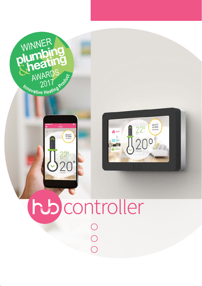
Award winning
smart thermostat
installation guide
Smartphone control
1
No additional wiring
2
3
Works with all heating systems
Page 2
Contents
1
2
3
4
5
6 7 8
9
Technical specifications
Compatibility
Replacing a mechanical thermostat
Wiring diagram single zone
Wiring diagram two zones
Wiring diagram three zones
Replacing a time clock
Wiring diagram single zone
Installation steps
Setup
Alternative installation modes
Switching a pump
In parallel with a time clock
Troubleshooting
Page 3
Technical specifications
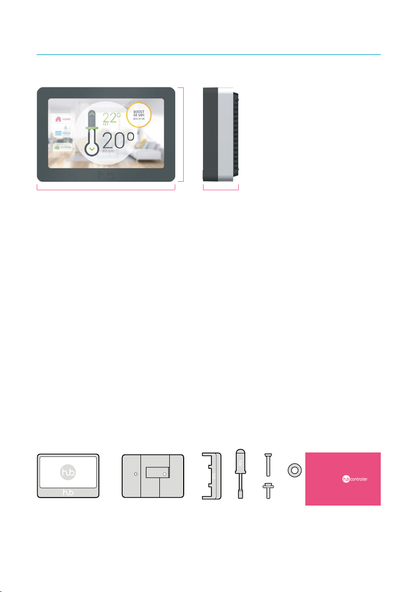
88mm
129mm
32mm
Features
Measures temperature and humidity•
••Manual and remote temperature control
Displays the measured temperature
Allows the adjustment of operation
•
and set point
Setting a schedule•
Over-the-air firmware updates
•
Holiday mode with frost protection
•
Budget control
•
Wireless and Security
Self-contained ultra-low power Wi-Fi module
IEEE Wi-Fi 802.11 b/g/n Wi-Fi transceiver
802.11g: up to 54 Mbps
Frequency Band 2.484 GHz (WLAN Channels 1-13)
Wi-Fi security modes including Open, WEP, WPA, and WPA2-PSK
Data encryption: TLS1.2 (SSL)
Sensor
Temperature sensor range and accuracy: 0°- 65° ± 1.0°C
Box contents
This is everything you will need to
install the HUB Controller.
HUB display
HUB back plate
Screwdriver
Child-safe removal tool
Screen
TFT LCD resistive touch screen
Resolution: 800 x 480 px
5in (12.7 cm) diameter
Size and Weight
Weight: 320 g
Width: 5.12 in (130 mm)
Height: 3.46 in (88 mm)
Depth: 1.29 in (32.75mm)
Screwdriver
Screws
Washer
Quick start guide
Quick start guid e
1
Page 4
Compatibility
The HUB Controller was built to directly replace the existing heating controls. It measures room temperature
and allows the user to modify operation and set point temperature. It can be installed in any household with
an individual heating system.
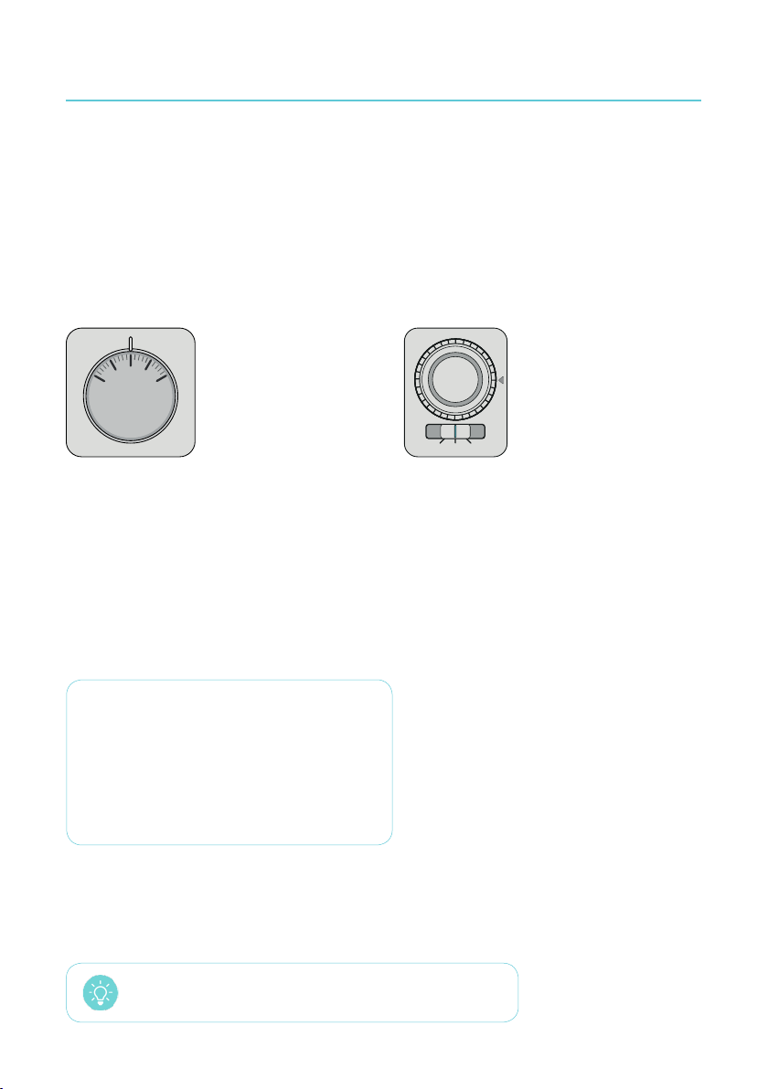
The HUB Controller can replace:
Mechanical thermostat Time clock or programmer
20
25
15
30
10
o
C
CLOCKOFF
ON
2-wire system:
Mechanical thermostats usually only use 2 wires,
without the neutral wire hence the name
2-wire system.
3-wire system:
When heating controls directly connect to a higher
load (e.g. directly to boiler, pump or 2+ valves), the
neutral wire is required. This setup is known as
3-wire system.
If there is neither a mechanical thermostat nor a programmer or a timer clock controlling the heating
system, the HUB Controller may still be compatible. Please call +353 1 901 0367 and we’ll evaluate the
system.
Power requirements
Voltage: 230 V AC +/-10%
Frequency: 50 Hz
Maximum load: 50 mA w/o neutral, 2 A w/ neutral
Load types and ratings
2-wire system: max 2 valves (25 mA each)
3-wire system: load max 460 W (boiler&pump)
The HUB Controller is compatible with 99.3% of all boilers.
2
Page 5
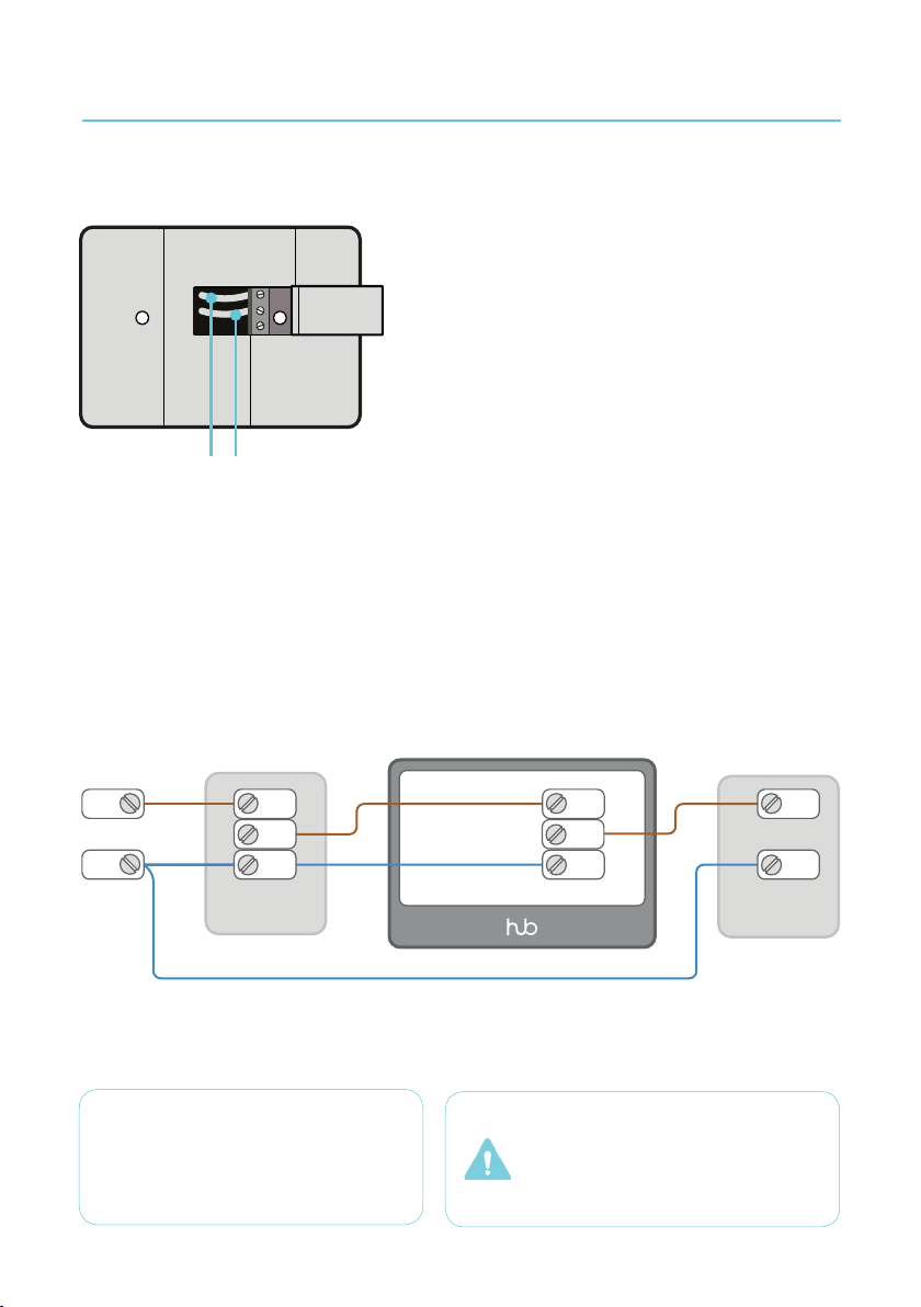
Replacing a mechanical thermostat
The HUB Controller can replace any mechanical
thermostat, regardless of the fuel type.
Mechanical thermostats usually only use 2 wires and the
HUB Controller has been designed to work specifically in this
situation.
It has a rechargeable battery that is powered by the existing
2 wires on the wall. This patented technology allows the
HUB Controller to charge itself without requiring a neutral
L
L V1
Live wire
V1
Control wire
Wiring diagram single zone
wire. This solution makes the HUB Controller compatible
with any heating system, without any need to change the
existing wires.
230 V~ | 50Hz
L
LIN
LOUT
N
NOTE: The heating channel on the pro-
grammer/time clock must be set to always
ON. For an alternative wiring in parallel,
see the diagram on page 8.
N
time clock
L
L
V1
N
WARNING! Your wire colours and
functions may dier. If you are not sure
which wires are the live and neutral wires,
have a trained electrician perform the
installation.
N
boiler
3
Page 6
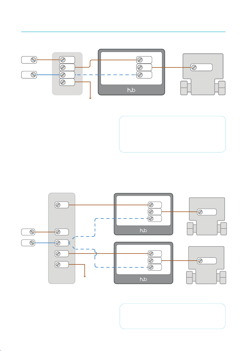
Wiring diagram two zones
230 V~ | 50Hz
L
N
Wiring diagram three zones
L
CH
N
HW
time clock
cylinder stat
NOTE: In a standard two-zone heating system, the
HUB Controller can be fitted without a neutral
wire. However, if the neutral wire is present when
you remove the thermostat, you should always
connect it to the N connector.
L
V1
N
brown
valve
230 V~
50Hz
L
N
4
CH1
L
N
CH2
HW
time clock
cylinder stat
L
V1
N
L
V1
N
brown
CH1
valve
brown
CH2
valve
NOTE: In case of fitting the HUB Controller in a
multizone system, you will need a HUB Controller
per zone.
Page 7
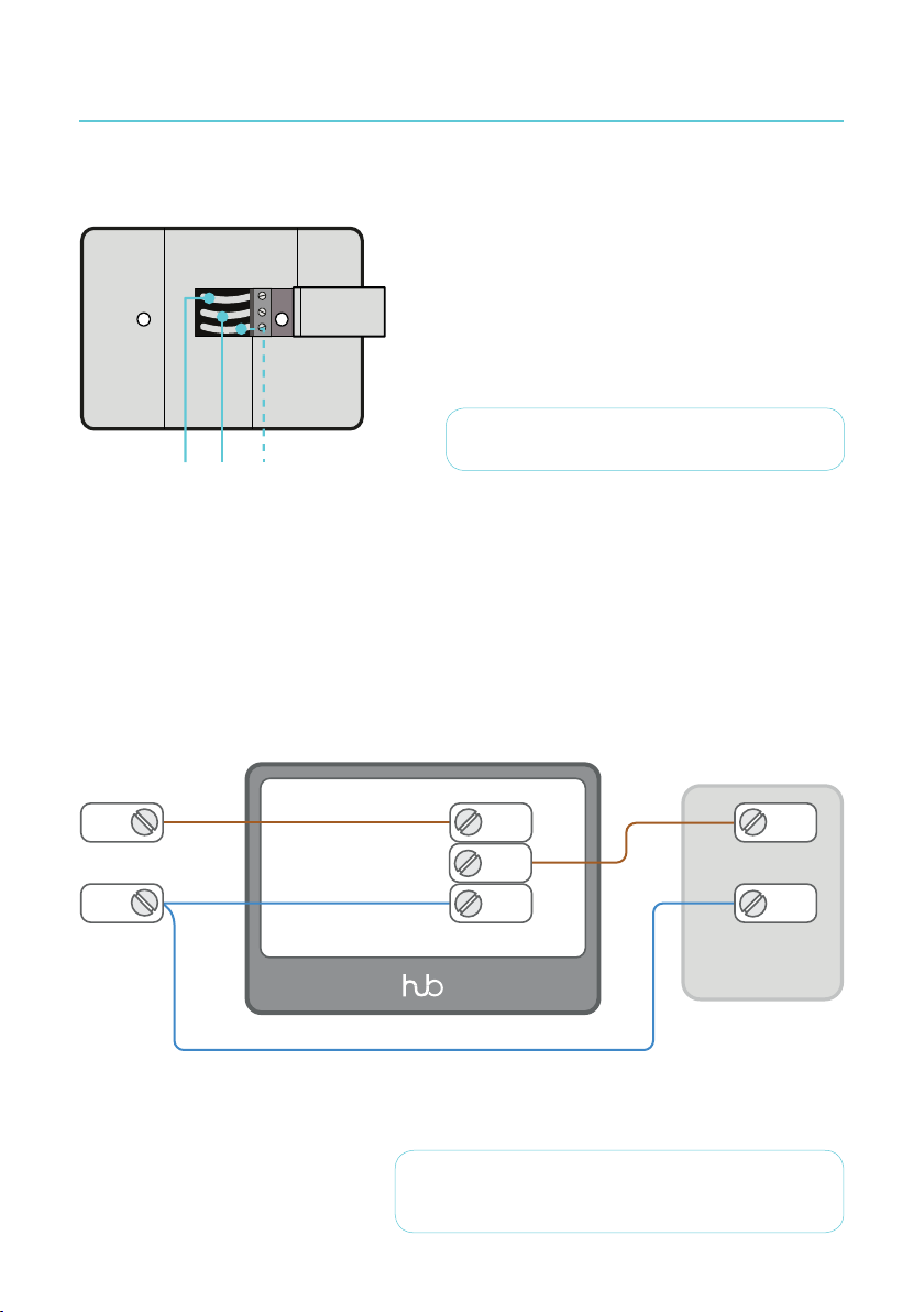
Replacing a time clock
In a heating system without a thermostat, the HUB
Controller can replace a time clock or a programmer.
Because the existing time clock/programmer is directly
controlling a boiler or a pump, there is always a neutral
wire. In this case, the neutral wire must be connected to
the N connector on the bottom.
L V1
N
L Live wire
V1 Control wire
N Neutral wire
Wiring diagram single zone
230 V~ | 50Hz
L
N
WARNING! Maximum switching current is 2 A.
L
V1
N
boiler
L
N
IMPORTANT! Replacement of a time clock/programmer
always requires use of neutral wire.
5
Page 8
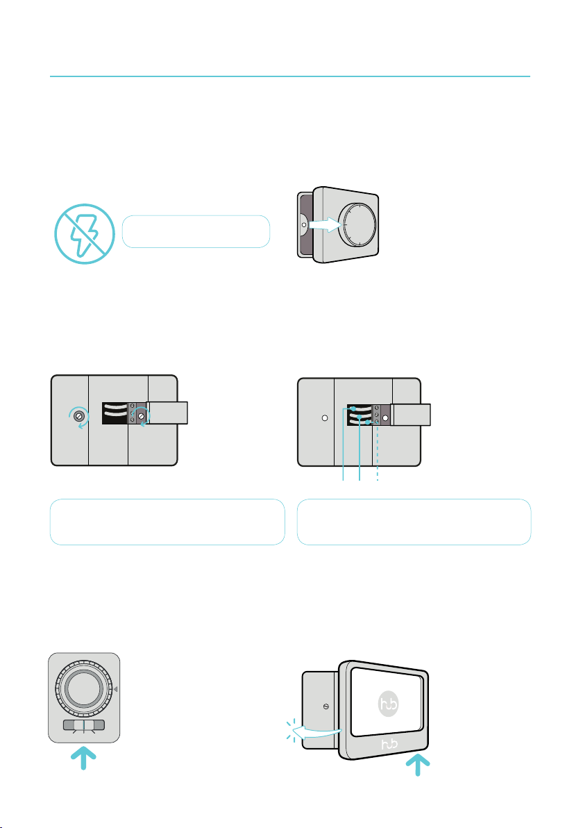
Installation steps
Step 1
Establish that the existing heating controls are in fact
controlling the heating. Turn o the power to your
heating system at the mains. To ensure the wires do
NOT have power running to them, use a mains tester.
WARNING! HIGH VOLTAGE
Step 3
Tighten the HUB base plate to your wall using the
screws provided. Don’t forget to use the washer to
make sure it’s level.
NOTE! Overtightening the screws may interfere
with proper operation.
Step 2
Remove your existing thermostat or time clock or
programmer. If required, test each wire to determine
its function. Label and safely disconnect the wires.
Step 4
Identify your wiring, and then see the appropriate
wiring diagram. Connect the L to the top, V1 to the
centre, and, if applicable, N to the bottom. If this is
your first installation, you may want ot check the
troubleshooting section for more info.
L Live wire
V1 Control wire
N Neutral wire
LV1N
WARNING! Installing the wires incorrectly will
damage your HUB.
Step 4a
If applicable, set your programmer or time clock to
always on.
Turn on the mains electrical power.
CLOCKOFF
ON
ON
6
Step 5
Connect the HUB Display to the base plate aligning
the display with the right side of the base plate.
Then push the le side into place until it ‘clicks’. The
HUB Controller will start automatically, so follow the
on-screen instructions to proceed to setup.
CLICK
Page 9
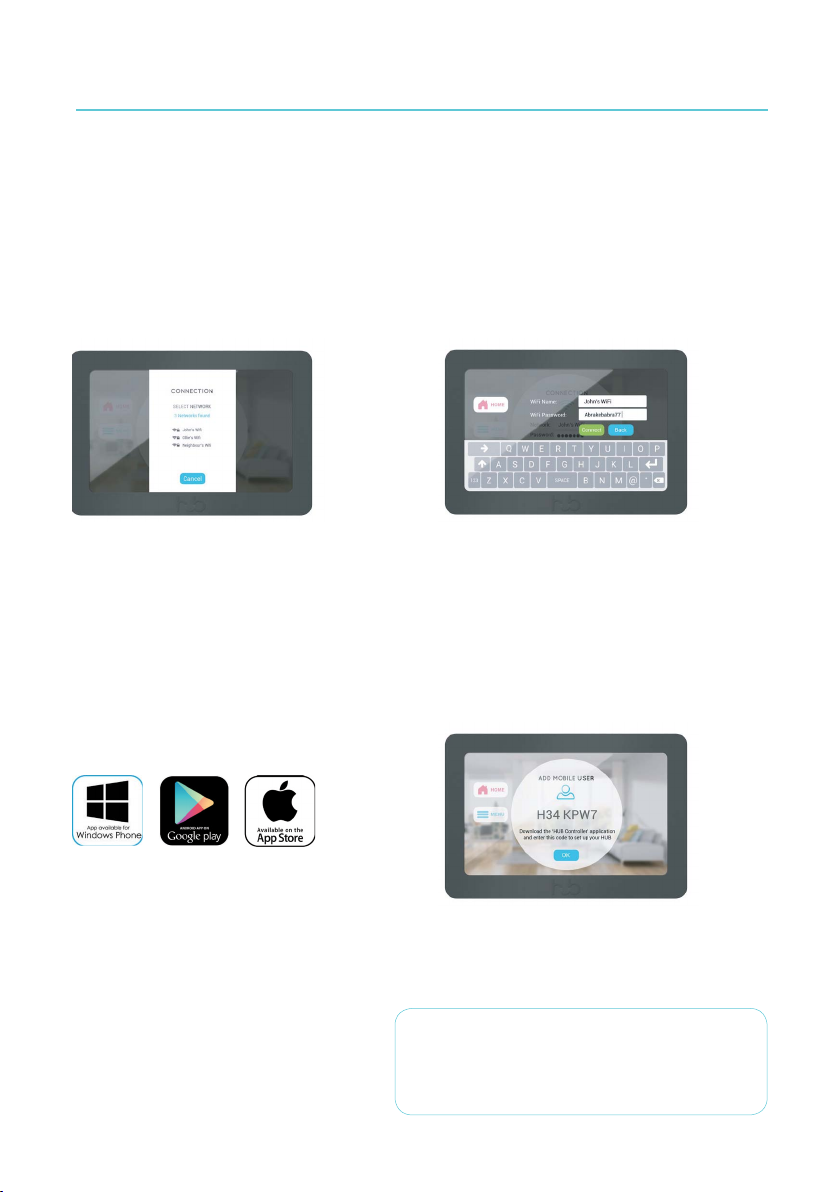
Setup
Aer the installation is complete, the HUB Controller will start automatically.
Step 1
Select the network
The device will begin to scan for wireless networks.
Once the HUB has discovered all the available networks, select the home’s Wi-Fi from the list.
Step 3
Download the app
In order to connect the HUB to a mobile phone, you
need to install the HUB Controller app on the phone.
While the HUB is connecting, download the HUB
Controller app from the online store.
Step 2
Enter the network details
Once the Wi-Fi network has been selected, type in
the password to access it.
Step 4
Add a mobile user
Once the connection has established, the HUB can
now be connected to a mobile phone. Go to Menu
and click on Pairing. The device will display 7
digits. Type that code into the mobile phone app to
pair the phone with the device.
NOTE: The HUB Controller will operate on its own
without being connected to Wi-Fi. However, a Wi-Fi
connection is required to control the device from
the HUB Controller mobile app.
7
Page 10
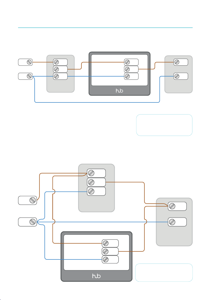
Alternative installation modes
Switching a pump
230 V~ | 50Hz
L
L
N
IN
L
OUT
N
L
V1
N
L
N
time clock
In parallel with a time clock
230 V~
50Hz
L
time clock
N
pump
IMPORTANT! Connecting
a HUB directly to a pump
requires use of neutral wire.
L
IN
L
OUT
N
L
N
L
boiler
V1
N
NOTE: Put your programmer
or clock to always o.
8
Page 11
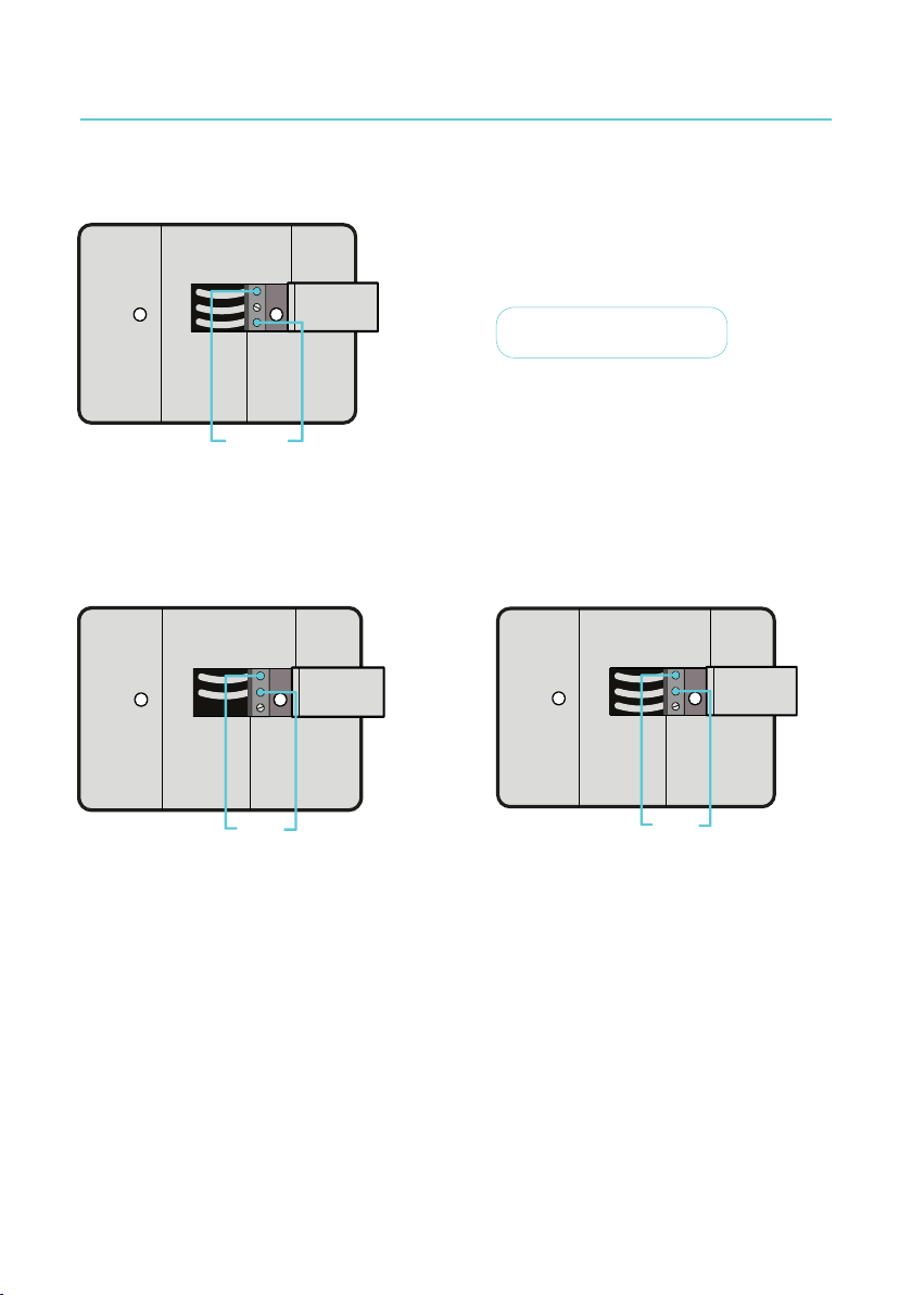
Troubleshooting
How to test a power supply?
230V
Measuring the voltage
Aer you turn on the mains electrical power,
check voltage 230 V AC between L & N.
WARNING! HIGH VOLTAGE
50mA
Measuring the current in 2-wire system
The switching current between L & V1 should not
exceed 50 mA.
2A
Measuring the current in 3-wire system
The maximum switching current between L & V1
is 2 A.
9
Page 12

 Loading...