

Page 1
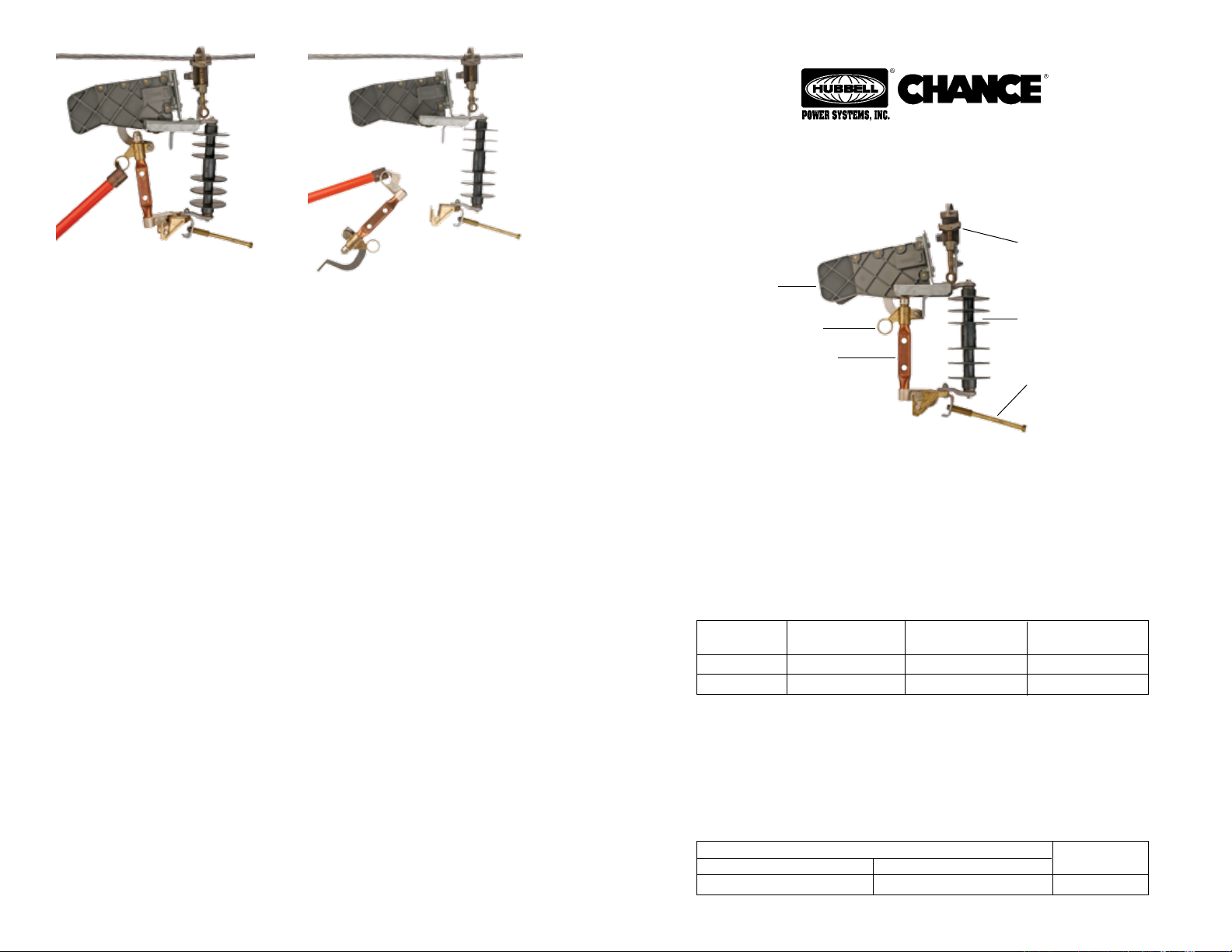
FIGURE 4
FIGURE 5
Removal
To remove the Temporary Load Disconnect Tool, while maintaining a continuous
circuit connection, first make up a permanent connection or replace the previously removed permanent connection, in parallel with the tool. Now there are
two energizing paths.
This tool is equipped with an arc-chute type interrupter. The arc chute enables
the tool to perform as a loadbreak device capable of interrupting load currents.
To operate this loadbreak device, place a disconnect stick in the pull ring on the
blade (see Figure 4). Position yourself approximately 2 feet to one side of the
tool. Look away from the tool and pull sharply on the disconnect stick without
hesitation. After opening blade, swing it into a full open position. Use a disconnect
stick to remove the blade from the lower hinge (see Figure 5). With a Grip-All
clampstick remove the temporary jumper from the energized conductor and
secure it on the stud at the lower hinge. With a Grip-All clampstick remove the
tool from the energized line conductor (see Figure 1).
Checklist
1. Check tool for proper closing and latching before each use.
2. This product should not be installed for extended periods. With the blade
removed, the insulator may permit excessive leakage depending upon surface contamination and the extent of surface wetting. Wiping the insulator
with a clean Chance Wiping Cloth (Cat. No. M1904) or a silicone material
will help resist this condition.
3. To assure proper closing and opening operations, always close the blade in
line with the insulator.
4. When attaching jumper clamp to load, do not pull tool out of vertical posi
tion.
5. Inspect contacts for excessive pitting or burning and replace as necessary.
Check blade for burrs or excessive erosion and replace if necessary. Check
arc chute for cracks and replace if broken.
6. When not in use or when in storage,
provided.
7. After approximately 50 operations, inspect the entire tool as described in
Item 5 above.
NOTE: Because Hubbell has a policy of continuous product improvement, we reserve the right to
change design and specications without notice.
©
Copyright 2007 Hubbell Power Systems, Inc. Printed in USA
P6002400
Rev. A
always keep tool in the storage case
OPERATING INSTRUCTIONS FOR
Temporary Load Disconnect Tool
Catalog No. Application
PSC6010347 8.3/15kV
PSC6010348 15/27kV
Line Conductor Clamp
Load-Break
Arc Chute
Pulling Eye
Blade
This unfused tool provides a temporary means of connecting and disconnecting
equipment or circuits under load conditions. This tool does not provide fault
or overcurrent protection. It has no fuse. It should never be closed into a fault
or opened during a fault. Unfused or unswitched loads can be disconnected by
first installing this tool with a temporary bypass jumper in parallel with the
permanent tap connection. After closing the blade of the tool, the permanent tap
can be disconnected. The load can then be dropped or reconnected by operating
the blade of the tool.
Ratings and Specifications
System
Class
8.3/15kV*
15/27kV*
* For application on single-phase-to-neutral or three-phase solidly-grounded-
wye connected circuits where recovery voltage does not exceed the maximum
design voltage of the device.
†
This is a pass-through fault current rating only.
The tool should never be opened or closed when the current exceeds the
maximum continuous load current of 300 amps.
#6 solid copper (0.162")
Max. Loadbreak
Current
300 Amps
300 Amps
Main Line Range
Minimum
Max. Momentary
Rating (Amps)
12,000† Asym
12,000† Asym
Both Models
Maximum
954 kcmil ACSR (1.20")
Insulator
Tap Stud for
Temporary Jumper
Epoxiglas
Insulation Length
63/4" length
101/8" length
1
®
Tap
Stud
/2" diameter
P6002400
Rev. A
Page 2
! WARNING
▲
The equipment covered by this instruction guide should be selected, installed and
serviced by competent personnel who understand proper safety procedures. This
instruction guide is written for such personnel and is not a substitute for adequate
training and experience in safety procedures regarding this type of equipment. This
guide does not claim to cover all details or variations in equipment nor to provide
for all possible conditions to be met with concerning installation, operation or maintenance of this equipment. If further information is desired or if particular problems
are encountered which are not sufficiently covered in this guide, contact Chance.
! CAUTION
▲
The equipment covered here is for temporary use only; it is not to be used permanently in place of a cutout or a switch.
! WARNING
▲
Do not close or open this tool on a faulted circuit.
! WARNING
▲
Proper size and rating of the temporary load disconnect tool must be selected for
each installation. Should there be any concern regarding use of this tool as rated,
consult your supervisor before installation.
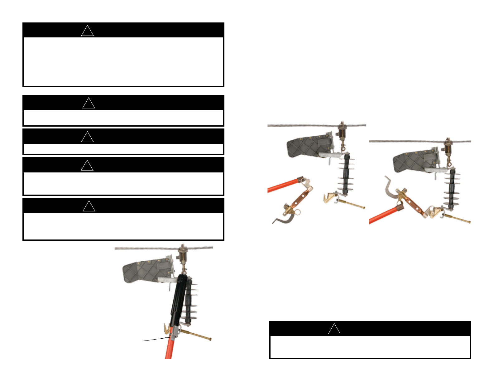
Securely attach both clamps of a suitable temporary jumper onto the tap stud
on the lower hinge.
With the blade removed, use a Grip-All clampstick to install the tool securely
on the energized line conductor (see (Figure 1). Mount the assembly vertically
and allow for clearance above and below the tool to adjacent phase conductors
and grounds.
Again using a Grip-All clampstick, place one of the jumper clamps on the load
to be picked up (such as apparatus jumper or branch line). When attaching
jumper to load, do not pull tool out of vertical position.
With a disconnect stick place the blade in the lower hinge of the tool (see Figure
2).
! CAUTION
▲
Only qualified personnel should operate a temporary load disconnect tool. Those
personnel must wear appropriate protective equipment such as rubber gloves,
hard hats, safety glasses, etc. in accordance with established utility and safety
practices.
Installation
Remove blade from the temporary load disconnect tool.
Do not proceed with blade in
the temporary load disconnect tool.
Do not exceed load current
rating of 300 amps.
Blade Removed
Grip-All
Clampstick
FIGURE 1
FIGURE 3FIGURE 2
Positioning yourself approximately 2 feet to one side of the tool, place the disconnect stick in the pulling eye and rotate the blade to an intermediate position as
shown in Figure 3. Look away from the tool. Quickly and firmly drive the blade
into the closed position. Remove the disconnect stick from the pulling eye carefully to avoid opening the blade.
The equipment or circuit is now energized through the temporary load disconnect tool. See following instructions for removing the temporary load disconnect
tool.
! WARNING
▲
Hot gases and particles are expelled from the arc chute during opening. These can
cause personal injury. Look away and position yourself to the side of the arc chute
when opening.
 Loading...