

Page 1
Revision A
05/18
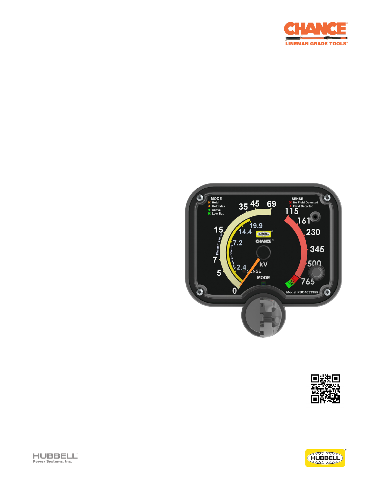
CHANCE® Multi-Range Voltage Indicator
Operating Instructions Model No. PSC4033955
For use on Transmission voltages up to 765 kV AC
NOTICE: Before operating a Chance® Multi-Range
Voltage Indicator (MRVI), thoroughly read, understand
and follow these instructions. Keep these instructions
with product for future reference.
Hubbell has a policy of continuous product improvement. Please visit hubbellpowersystems.com to confirm current design specifications.
©2018 Hubbell Incorporated | hpsliterature@hubbell.com | hubbellpowersystems.com
Page 2
Guide to Warnings within Manual
The following is a list of warnings used within this manual and should be read in their entirety to
ensure safe practices.
DANGER
!
A DANGER refers to operating procedures, techniques, etc., that, if not followed carefully could
RESULT IN DEATH.
WARNING
!
A WARNING refers to operating procedures, techniques, etc., that, if not followed carefully could
RESULT IN INJURIES OR DEATH.
CAUTION
!
A CAUTION refers to operating procedures, techniques, etc., that, if not followed carefully could
RESULT IN DAMAGE TO EQUIPMENT or LOSS OF SERVICE to customers.
NOTICE
A NOTICE refers to information that is considered important but not hazard related.
©2018 Hubbell Incorporated | Chance® Multi-Range Voltage Indicator Operating Instructions
2
Page 3
Product Safety
WARNING
!
Do not allow the universal coupling or housing to become grounded in any way, or to contact
another phase as this will cause erroneous voltage indication and could cause severe personal
injury or damage to equipment.
WARNING
!
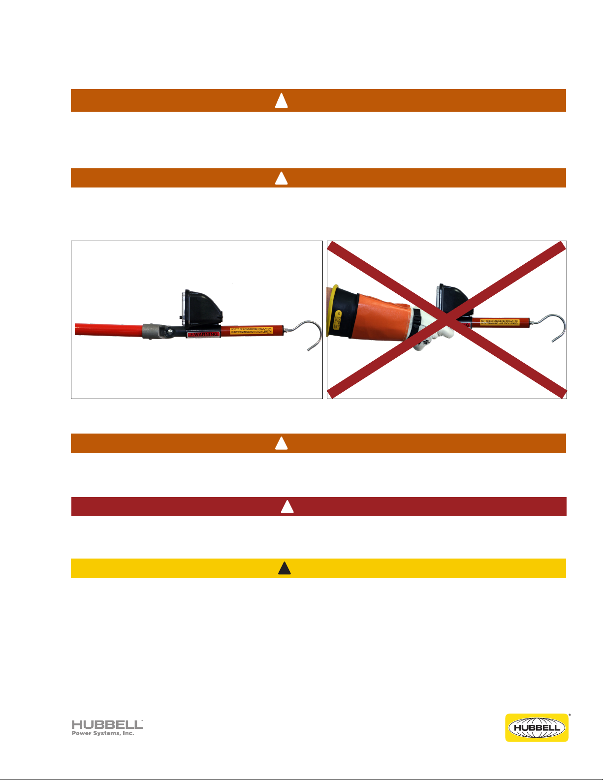
Always use an appropriate length insulated Hot Stick even when wearing rubber gloves. Contact
with the universal coupling or other parts, even with rubber gloves, will cause erroneous voltage
indication. Always use with a universal pole to maintain its calibration.
CORRECT USE INCORRECT USE
WARNING
!
Before and after each use, always test the unit on a known energized voltage source or with the
Voltage Indicator Tester to verify proper operation.
DANGER
!
Minimum Approach Distances (MAD) should be adhered to at all times. For the latest information
and charts refer to the official OSHA website: https://www.osha.gov
CAUTION
!
The equipment covered in this manual must be used and serviced only by competently trained
personnel familiar with and following approved work and safety practices. This equipment is for
use by such personnel and this manual is not intended as a substitute for adequate training and
experience in safe procedures for this type of equipment.
These instructions neither cover all details or situations in equipment use, nor do they provide for
every possible contingency to be encountered in relation to installation, operation or maintenance.
Should additional information and details be desired or if situations arise which are not covered
adequately for the user’s purpose, the specifics should be referred to Hubbell Power Systems.
©2018 Hubbell Incorporated | Chance® Multi-Range Voltage Indicator Operating Instructions
3
Page 4

Function and Design Overview
The CHANCE® Multi-Range Voltage Indicator® (MRVI), model number PSC4033955, is a portable
tool used to confirm whether an AC (Alternating Current) Transmission high voltage power circuit
is energized or de-energized prior to performing maintenance. The instrument has been specifically
designed to work with Transmission voltages (69 kV through 765 kV). It also provides the user the
ability to observe lower voltages that may be present due to induction or storm emergency situations.
It provides field practicality over the two points of contact measurement method. Readings from the
MRVI represent the class of voltage that is present on the line. The MRVI is designed to determine
approximate Phase-to-Phase and Phase-to-Ground nominal voltage. This unit is a direct contact
electric field intensity indicator.
The MRVI is used as a secondary means to confirm the condition of a circuit after principal work
procedures such as visible open gaps, dispatcher hold orders, and apparatus tag-outs have rendered
the circuit de-energized.
For Distribution voltages, including Capacitive Test Point, we would recommend utilizing the
Distribution MRVI, model PSC4033710, which is specifically designed for those ranges.
NOTICE
This device is an AC (alternating current/alternating voltage) only indicator; do not use it to detect
DC (direct current/non-alternating voltage).
WARNING
!
Before and after each use, always test the unit on a known energized voltage source or with the
Voltage Indicator Tester to verify proper operation.
Features
• Meets intent of OSHA 1910.269 to test for absence of nominal voltage
• Used to determine if power lines are at rated voltage, have induced voltage, or are de-energized
• For overhead and underground systems (with appropriate adapters and Hot Sticks)
• Stepper motor technology
• Illuminated fluorescent pointer
• Power-saving sleep mode (auto-off)
• Checks battery voltage on initial startup
• Positive interface power button
• Equivalent Phase-to-Phase and Phase-to-Ground reading ranges
• Manually activated Hold Mode
• Bluetooth technology
• New lightweight design (19.8 oz without batteries)
• Battery drawer for simple battery replacement
• Comes with a storage bag with a snaphook designed to attach to a lineman's belt
• QR code located in the instructions, Quick Reference guide, and on the unit itself
©2018 Hubbell Incorporated | Chance® Multi-Range Voltage Indicator Operating Instructions
4
Page 5
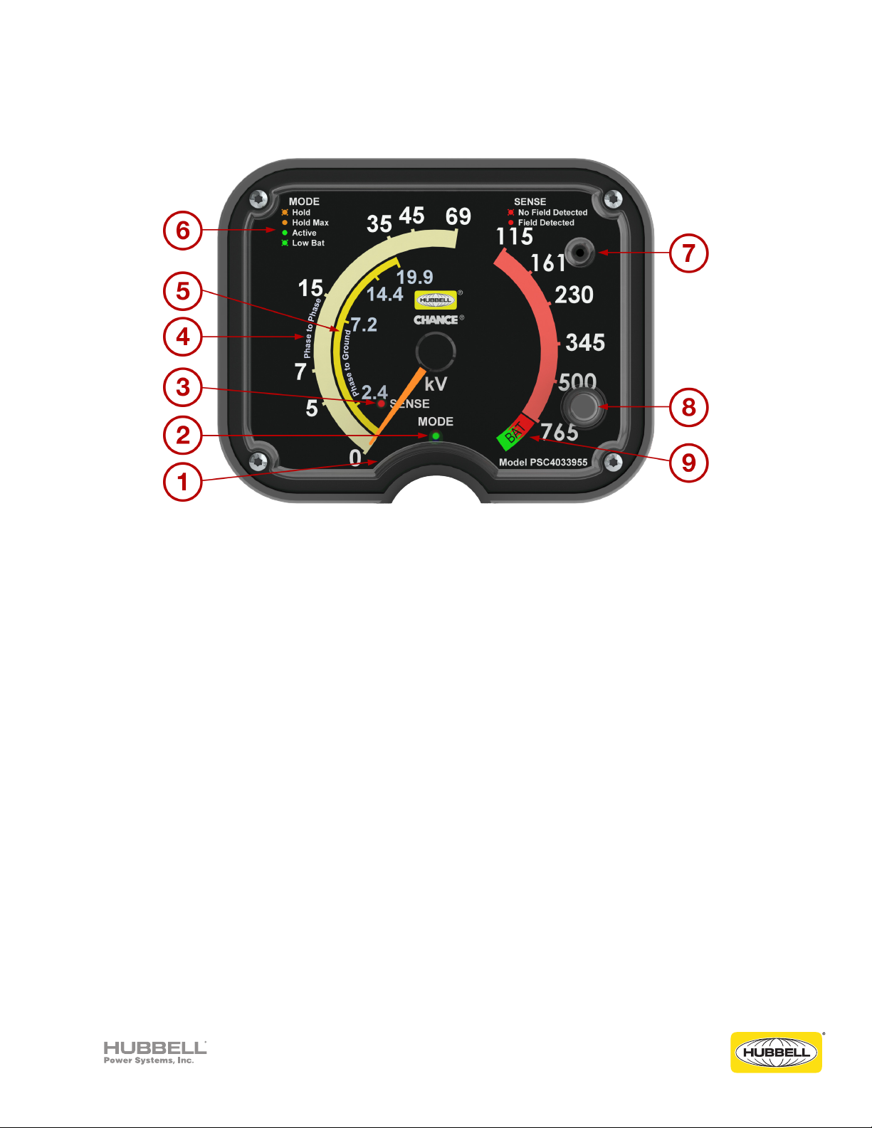
Front Panel Information
1. Pointer Stop
2. Mode LED
3. Sense LED
4. Phase to Phase Scale
5. Phase to Ground Scale
6. LED Legend
7. Audible Alarm
8. Power Button
9. "BAT" Battery Voltage Level
Indicator
Accuracy
This instrument is not a voltmeter; hence, the manufacturer claims no specific accuracy and therefore
no specific accuracy is to be assumed by the user. Readings will vary with the field intensity,
determined by a great variety of field conditions including proximity, size, and orientation of all system
components in the vicinity, both energized and grounded. Erroneous readings may result from being
placed near other energized conductor, sources, or grounds. To avoid such field distortions: keep the
unit as far away as practical from all system components other than the specific conductor being
tested.
©2018 Hubbell Incorporated | Chance® Multi-Range Voltage Indicator Operating Instructions
5
Page 6

Operating the MRVI
To Turn the Unit On:
1. Momentarily depress the “Power Button.”
a. The “Mode LED” (Light Emitting Diode) will continuously illuminate green, indicating the unit is
active. The pointer will rotate counter-clockwise against the "Stop" and will momentarily move
clockwise to the zero mark. The audible alarm will sound once to indicate the power is on.
b. The pointer will pause at the zero mark for approximately 1 to 2 seconds before proceeding in
the clockwise direction to a zone on the dial face marked, “BAT.” The pointer will remain in this
zone for approximately 4 to 5 seconds to indicate the current condition of the batteries. If the
pointer is in the green “BAT” zone the batteries are good. If the pointer is in between the green
and red “BAT” zones the batteries should be replaced soon. If the pointer is in the red “BAT”
zone or the “Mode LED" is flashing green the batteries should be replaced immediately.
c. After the pointer has indicated the condition of the batteries, the pointer will recalibrate its
position by rotating counter-clockwise below the zero mark (to the "Stop") and then move
clockwise to the zero mark. The audible alarm will sound once and the “Sense LED" will
illuminate, flashing red, if no electric field is currently being detected.
d. The MRVI is ready for use once it is installed on an appropriate length insulated Hot Stick.
Taking a Reading:
2. Place the installed Shepherd Hook in contact with the power line conductor.
a. The "Sense LED" has been designed to change from flashing to continuously illuminated as the
electric field increases in intensity and reaches a potential that is greater than or equal to 1 kV
AC Phase-to-Phase.
b. The pointer will rotate and indicate a voltage level present on the power line conductor.
Hold Mode: Refer to page 7.
Turning the Unit Off:
3. To turn the MRVI off:
a. Press and hold the "Power Button" for 3 seconds:
i. The "Mode LED" and "Sense LED" will turn off.
ii. The pointer will rotate counter-clockwise until it rests against the Stop.
iii. The audible alarm will generate three tones in decreasing pitch.
b. Or the MRVI will automatically power itself down (auto-off) after approximately 15 minutes of
inactivity.
Before and after each use, always test the unit on a known energized voltage source or with the
Voltage Indicator Tester to verify proper operation.
1
WARNING
!
1
The “Sense LED” may change from flashing to continuously illuminated at voltages less than 1 kV AC Phase-to-Phase due to
the influences of other nearby energized conductors, static charges and other environmental conditions.
©2018 Hubbell Incorporated | Chance® Multi-Range Voltage Indicator Operating Instructions
6
Page 7

Hold Mode
Hold Mode:
To place the MRVI in the Hold Mode:
a. Make certain that the MRVI is powered on and active by momentarily depressing the “Power
Button.”
b. While holding the installed Shepherd Hook (or other appropriate adapter) away from the high
voltage source, press the "Power Button" twice in rapid succession to place the MRVI into the
Hold Mode.
c. Once the MRVI is in its Hold Mode the "Mode LED" will flash orange and the audible alarm will
chirp continuously to let you know the MRVI is in the Hold Mode.
d. The pointer will rotate counter-clockwise until it encounters the "Stop" and then it will return
to the zero mark on the dial.
e. Place the installed adapter in contact with the power line conductor:
i. The "Mode LED" will begin to flash orange.
ii. The audible alarm will begin to beep in higher and higher pitch.
iii. The pointer will rotate to indicate the voltage level present on the power line conductor.
f. Once the MRVI has sensed a constant value of the voltage level present on the power line
conductor:
i. The "Mode LED" will change from flashing to a continuously illuminated orange color.
ii. The audible alarm will sound a continuous tone and the pointer will hold on the peak value.
g. Once the MRVI is removed from the power line conductor, the pointer will remain on hold until
the “Power Button” is rapidly depressed a single time, placing the MRVI back into the active
state.
h. Once the "Power Button" is depressed:
i. The pointer will rotate counter-clockwise until it encounters the "Stop" and then it will
return to the zero mark on the dial.
ii. The audible alarm will cease to generate a tone.
iii. The "Mode LED" will illuminate green to indicate the MRVI is in its active state and is ready
to resume taking readings.
CAUTION
!
In the Hold Mode the MRVI is waiting for a steady (consistent) voltage reading before holding a
reading. Movement of the MRVI's Shepherd Hook (or other appropriate adapter) in the electric
field during the Hold Mode will cause a delay in capturing the reading. Keep the MRVI steady and
in constant contact with the conductor until the "Mode LED" is continuously illuminated (orange
color) and the audible alarm produces a continuous tone. To return to an active state, the indicator
must be reset.
©2018 Hubbell Incorporated | Chance® Multi-Range Voltage Indicator Operating Instructions
7
Page 8

Operations for Overhead
NOTICE
Both the electromagnetic action of current and electrostatic action of voltage can induce a high
static condition on the de-energized circuit. Activity effects can exist between all conductor pairs.
The MRVI indicates the combined field intensity from all other conductors, including ground wires.
©2018 Hubbell Incorporated | Chance® Multi-Range Voltage Indicator Operating Instructions
8
Page 9

Operations for Underground
Always use appropriate length insulated Hot Stick even when wearing rubber gloves. Contact with
universal coupling or other parts, even with rubber gloves, will cause erroneous voltage indication.
Also, due to the close proximity of conductive metals, the readings taken in underground cabinets
will typically be higher than on an overhead line.
As with overhead, the same basic rules and procedures apply when using the CHANCE® Multi-Range
Voltage Indicator (MRVI) on underground systems. Follow these three very important additional
instructions when using the tool on underground equipment:
DANGER
!
1. When testing underground equipment, use an appropriate adapter rather than the short probe
or the Shepherd Hook.
2. Use extreme caution when testing underground equipment. Use all applicable safe work
practices and procedures. Do not use any probes on the MRVI when testing live-front URD
equipment. In place of a probe, use a small hex head machine screw (1/4-20 X 3/8" long).
3. When testing high voltage equipment, the MRVI may detect fields from adjacent conductors,
energized parts or grounds, including grounded cabinet components. Indication of an
energized field may not be sufficient to isolate one specific conductor. Should the user wish to
confirm a specific conductor is energized (or de-energized) further testing with a non-wireless
Phasing Set designed for this application will be required.
WARNING
!
Before and after each use, always test the unit on a known energized voltage source or with the
Voltage Indicator Tester to verify proper operation.
©2018 Hubbell Incorporated | Chance® Multi-Range Voltage Indicator Operating Instructions
9
Page 10

Battery Replacement
A low battery condition is indicated when the “Mode LED" is flashing green, or during start-up the
pointer is in the red “BAT” zone. Batteries can be replaced by carefully removing the two screws
on the battery drawer and sliding the drawer away from the housing to expose the battery holder.
Replace the four “AA” batteries, noting proper polarity. Either Alkaline or Lithium batteries may be
used.
NOTICE
This device contains no user serviceable components. Do not remove the front lens assembly.
CAUTION
!
Ensure that the wires connected to the battery holder remain connected and are not damaged.
After the battery drawer and screws are replaced in the housing, test the function of the unit on
a known energized voltage source or with the Voltage Indicator Tester, model PSC4033582, for
proper operation.
10
©2018 Hubbell Incorporated | Chance® Multi-Range Voltage Indicator Operating Instructions
Page 11

MRVI Remote Application (Apps)
Apps are available for the iPhone®, iPad®, and Android® operating systems to enable the operator to
remotely view the status of the MRVI.
1. Download the MRVI app from the Apple iTunes® or Google Play® stores.
2. Turn on the MRVI by momentarily depressing the “Power Button.”
3. Make sure that Bluetooth is enabled in the settings on your phone.
4. Activate the MRVI Remote app.
5. Once the app has linked to the MRVI, the smart phone display will show the readings of the MRVI.
6. To capture the data: take a screenshot according to your phone's instructions.
MRVI Remote App SELECT BUTTON
The app can link
up to four MRVIs
simultaneously
SELECT BUTTON: The app can link up to 4 MRVIs simultaneously.
1. If the app is linked to more than one MRVI, you may select which MRVI to monitor by tapping
on one of the active select buttons.
2. Turning off one of the MRVIs will disconnect that particular unit from the MRVI Remote app
and will remove the select button associated with that MRVI. All other MRVIs previously linked
to the app will remain linked and available for data display. For safety reasons, the app only
displays the information from the MRVI and does not control the operation of the MRVI.
©2018 Hubbell Incorporated | Chance® Multi-Range Voltage Indicator Operating Instructions
MRVI Remote App
displaying a MRVI
in Hold Mode
11
Page 12

Maintenance
The CHANCE® Multi-Range Voltage Indicator (MRVI) is an electronic instrument and, if properly cared
for, will provide many years of trouble-free service. Keep all parts clean and dry. Clean only with cloth
dampened with water. Do not use chemical solvents. Do not use CHANCE® Moisture Eater II wipes
on any part of the MRVI as it will cause damage.
Abuse or misuse will damage the unit. Store in a dry location, do not drop, and protect from jostling
or impacts during storage, carrying, or use. See page 14 "Specifications" for operating and storage
temperatures and humidity ranges.
CAUTION
!
Do not drop tool as accuracy may be impaired.
Repairs
For Hubbell Power Systems authorized repair or factory calibration, please contact:
M.W. Bevins Co.
9903 E. 54th St.
Tulsa, OK 74146
(918) 627-1273
(918) 627-1294 (FAX)
www.bevinsco.com
12
©2018 Hubbell Incorporated | Chance® Multi-Range Voltage Indicator Operating Instructions
Page 13
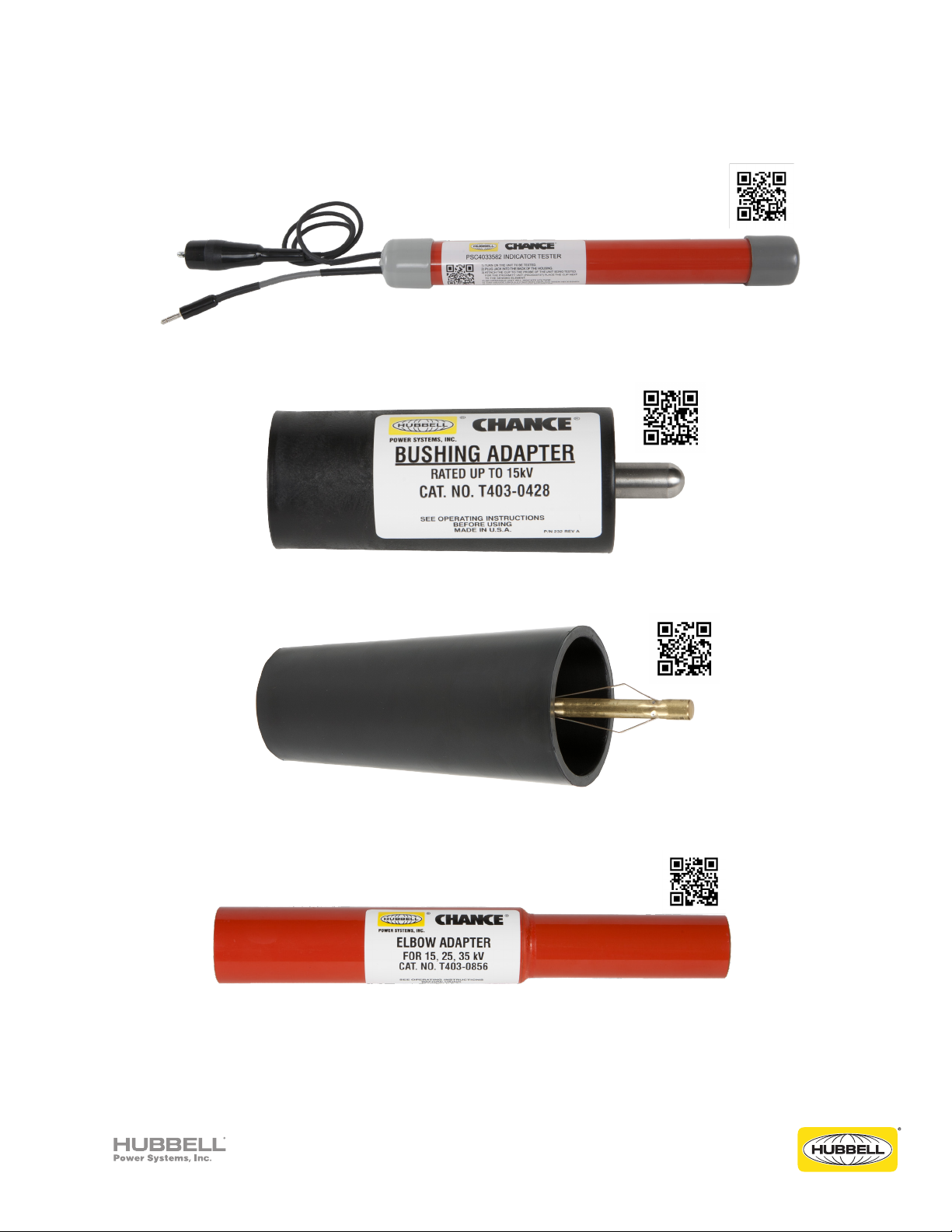
Optional Accessories
Indicator Tester - PSC4033582
15 kV Bushing Adapter - T4030428
15 kV, 25 kV, 35 kV Bushing Adapter - T4030857
Elbow Adapter - T4030856
©2018 Hubbell Incorporated | Chance® Multi-Range Voltage Indicator Operating Instructions
13
Page 14

Specifications
Weight (w/o batteries): 561 g (19.8 oz)
Dimensions: 12.55" L X 5.15" W X 5.06" H
Battery requirements: Four (4) Alkaline or Lithium “AA” batteries
Operating voltage range(s): 1 kV to 765 kV AC (Phase-to-Phase equivalent), 50/60 Hz
Operating temperature range: -20° to +80°C
Operating humidity range: 5% to 95% Rh
Storage temperature: -20° to +60°C (Recommended storage at 21°C +/- 2%°C)
Storage humidity range: 5% to 95% Rh (Recommended storage at 45% Rh +/- 8% Rh)
Shock Testing: per IEC 60068-2-27, "Test Ea and guidance: Shock"
Level 1 - 500 m/s2 (50g), 11ms Half-sine pulse, 3 pulses Positive & Negative, each axis.
Level 2 - 1000 m/s2 (100 g ± 4 g), 1.5 to 2.5ms Half-sine pulse, 3 pulses Positive & Negative, each axis
Vibration Testing: per IEC 60068-2-6, "Test Fc: Vibration (sinusoidal)"
1.5 mm p-p from 10 Hz to 40 Hz, 5g rms from 40 Hz to 2000 Hz for 3.3 hrs each axis
Limitations: Always use appropriate length insulated Hot Stick even if wearing rubber gloves. Always
test the unit before and after each use on a known energized voltage source or with the Voltage
Indicator Tester to verify proper operation.
FCC
Contains FCC ID: T9JRN4020
This device complies with Part 15 of the FCC Rules.
Operation is subject to the following two conditions:
(1) this device may not cause harmful interference, and (2) this device must accept any interference
received, including interference that may cause undesired operation.
14
©2018 Hubbell Incorporated | Chance® Multi-Range Voltage Indicator Operating Instructions
Page 15

Notes
___________________________________________________________________________________
___________________________________________________________________________________
___________________________________________________________________________________
___________________________________________________________________________________
___________________________________________________________________________________
___________________________________________________________________________________
___________________________________________________________________________________
___________________________________________________________________________________
___________________________________________________________________________________
___________________________________________________________________________________
___________________________________________________________________________________
___________________________________________________________________________________
___________________________________________________________________________________
___________________________________________________________________________________
___________________________________________________________________________________
___________________________________________________________________________________
___________________________________________________________________________________
___________________________________________________________________________________
___________________________________________________________________________________
___________________________________________________________________________________
___________________________________________________________________________________
___________________________________________________________________________________
___________________________________________________________________________________
___________________________________________________________________________________
___________________________________________________________________________________
___________________________________________________________________________________
___________________________________________________________________________________
___________________________________________________________________________________
©2018 Hubbell Incorporated | Chance® Multi-Range Voltage Indicator Operating Instructions
15
Page 16

Hubbell Power Systems, Inc.
210 N. Allen St
Centralia, MO 65240
www.hubbellpowersystems.com
Hubbell has a policy of continuous product improvement. Please visit hubbellpowersystems.com to confirm current design specifications.
PSP4 033799
TD_09_150_E
Rev A.
©2018 Hubbell Incorporated | hpsliterature@hubbell.com | hubbellpowersystems.com
 Loading...