

Page 1
Revision A
02/17
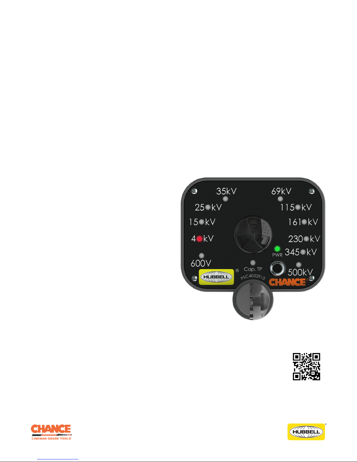
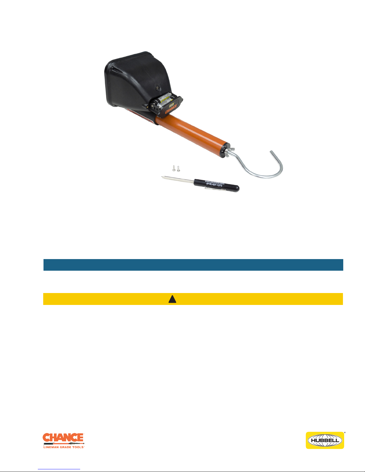
CHANCE® Full Range Auto-Ranging
Voltage Indicator
Operating Instructions Model No. PSC4032915
For use with Capacitive Test Point through 765 kV AC
NOTICE: Before operating a Chance® Full Range
Auto-Ranging Voltage Indicator (ARVI), thoroughly
read, understand and follow these instructions. Keep
these instructions with product for future reference.
Hubbell has a policy of continuous product improvement. Please visit hubbellpowersystems.com to confirm current design specifications.
©2017 Hubbell Incorporated | hpsliterature@hubbell.com | hubbellpowersystems.com
Page 2
Guide to Warnings within Manual
The following is a list of warnings used within this manual and should be read in their entirety to
ensure safe practices.
DANGER
!
A DANGER refers to operating procedures, techniques, etc., that, if not followed carefully could
RESULT IN DEATH.
WARNING
!
A WARNING refers to operating procedures, techniques, etc., that, if not followed carefully could
RESULT IN INJURIES OR DEATH.
CAUTION
!
A CAUTION refers to operating procedures, techniques, etc., that, if not followed carefully could
RESULT IN DAMAGE TO EQUIPMENT or LOSS OF SERVICE to customers.
NOTICE
A NOTICE refers to information that is considered important but not hazard related.
©2017 Hubbell Incorporated | Chance® Full Range ARVI Operating Instructions
2
Page 3
Product Safety
WARNING
!
Do not allow the universal coupling to become grounded in any way, or to contact another
phase as this will cause erroneous readings and could cause severe personal injury or damage to
equipment.
WARNING
!
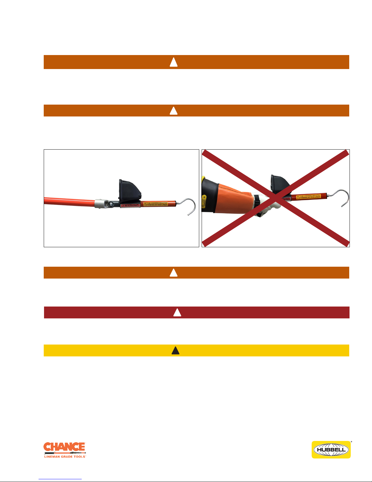
Always use an appropriate length insulated Hot Stick even when wearing rubber gloves. Contact
with the universal coupling or other parts even with rubber gloves will cause erroneous readings.
Always use with a universal pole to maintain its calibration.
CORRECT USE INCORRECT USE
WARNING
!
Before and after each use, always test the unit on a known energized voltage source or with the
Voltage Indicator Tester to verify proper operation.
DANGER
!
Minimum Approach Distances (MAD) should be adhered to at all times. For the latest information
and charts refer to the official OSHA website: https://www.osha.gov
CAUTION
!
The equipment covered in this manual must be used and serviced only by competently trained
personnel familiar with and following approved work and safety practices. This equipment is for
use by such personnel and this manual is not intended as a substitute for adequate training and
experience in safe procedures for this type of equipment.
These instructions neither cover all details or situations in equipment use, nor do they provide for
every possible contingency to be encountered in relation to installation, operation or maintenance.
Should additional information and details be desired or if situations arise which are not covered
adequately for the user’s purpose, the specifics should be referred to Hubbell Power Systems.
©2017 Hubbell Incorporated | Chance® Full Range ARVI Operating Instructions
3
Page 4

Function and Design Overview
The CHANCE® Full-Range Auto-Ranging Voltage Indicator (ARVI), model number PSC4032915, is a
portable tool to confirm that an AC (Alternating Current) high voltage circuit is energized or
de-energized prior to performing maintenance. It provides field practicality over the two points of
contact measurement method. Readings from the Full-Range ARVI represent the class of voltage that
is present on the line.
The Full-Range ARVI is used as a secondary means to confirm the condition of a circuit after
principal work procedures such as visible open gaps, dispatcher hold orders, and apparatus tag-outs
have rendered the circuit de-energized. The unit utilizes a single point of contact to the conductor,
therefore it is not a voltmeter. It is designed to determine approximate Phase-to-Phase nominal
voltage up to 765 kV AC 50/60 Hz.
The Full-Range ARVI is an electric field intensity indicator, which is calibrated to illuminate an LED
(light-emitting diode) representing the class of voltage that is present on the conductor. It responds
to the magnitude of the field gradient between its end probe and a floating electrode. The device
may also indicate the combined field intensity from nearby conductors, including ground wires and
grounded equipment. If the universal coupling is too close to a ground, another phase, or another
voltage source, the voltage indication will tend to be high. If the universal coupling is too close to a
jumper or equipment of the same phase, the indication will tend to be low. The tool must always be
used with an appropriate length Hot Stick for safety and to maintain its calibration.
NOTICE
This device is an AC (alternating current/alternating voltage) only indicator; do not use it to detect
DC (direct current/non-alternating voltage).
WARNING
!
Before and after each use, always test the unit on a known energized voltage source or with the
Voltage Indicator Tester to verify proper operation.
Features
• Meets intent of OSHA 1910.269 to test for absence of nominal voltage
• Used to determine if power lines are at rated voltage, have induced voltage, or are de-energized
• Capacitive Test Point through 765 kV AC for overhead and underground systems
• Adjustable audible alarm
• Power-saving sleep mode (auto-off)
• Approximate Phase-to-Phase voltage ranges are indicated by LED lights
• Automatic Hold Mode
• Battery drawer for simple battery replacement
• QR code located in the instructions and on the unit itself
Accuracy
This instrument is not a voltmeter; hence, the manufacturer claims no specific accuracy, and therefore,
no specific accuracy is to be assumed by the user. Readings will vary with the field intensity,
determined by a great variety of field conditions including proximity, size, and orientation of all system
components in the vicinity, both energized and grounded. Erroneous readings may result from being
too near other energized conductors or being too near another phase or ground. To avoid such field
distortions, keep the unit as far away as practical from all system components other than the specific
conductor being tested.
©2017 Hubbell Incorporated | Chance® Full Range ARVI Operating Instructions
4
Page 5
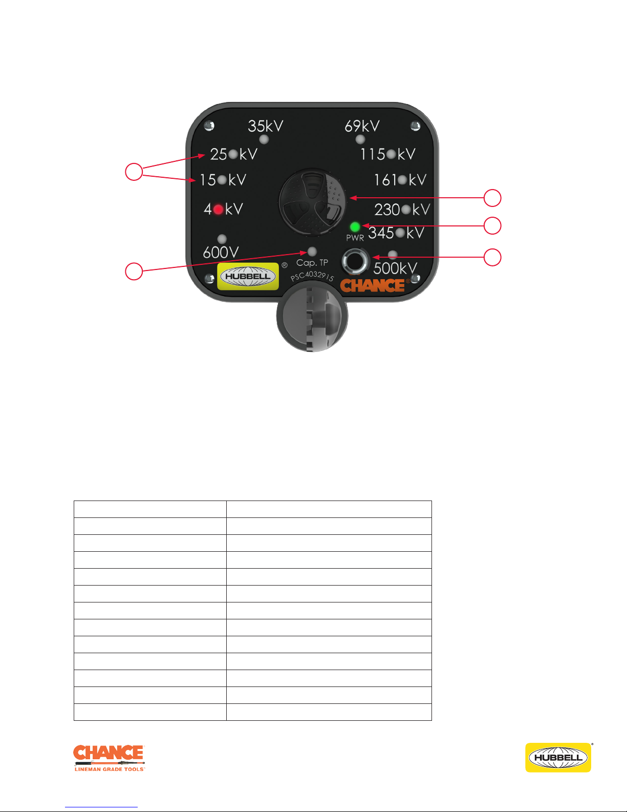
Front Panel Information
2
1
3
4
5
1. Capacitive Test Point (Cap. TP) LED
2. Range (600 V to 500 kV) LEDs
3. Audible Alarm
4. Power (PWR) LED
5. Power Button
Ranges
The equivalent voltage ranges to provide indication of each of the Voltage Classes are as follows:
Voltage Class Voltage Range
600 V 480 V to 900 V
4 kV 1 kV to 6.5 kV
15 kV 6.6 kV to 17 kV
25 kV 18 kV to 29 kV
35 kV 30 kV to 50 kV
69 kV 51 kV to 109 kV
115 kV 110 kV to 149 kV
161 kV 150 kV to 199 kV
230 kV 200 kV to 299 kV
345 kV 300 kV to 399 kV
500 kV 400 kV to 699 kV
765 kV 700 kV and above: all LEDs illuminate
©2017 Hubbell Incorporated | Chance® Full Range ARVI Operating Instructions
5
Page 6

Operations for Overhead
Turn the Unit On:
1. Momentarily depress the “Power Button” for approximately 2 seconds.
a. Upon power-up, each LED will illuminate individually from the lowest voltage to the highest
followed by the adjustable audible alarm. These tests verify the function of the LEDs, alarm,
batteries, and internal circuitry.
b. Following the adjustable audible alarm, the “PWR” LED will continuously flash. The unit is
ready for use.
c. Always install the unit on an appropriate length insulated Hot Stick.
Take a Reading:
2. Install the supplied Shepherd Hook and place the unit in contact with the power line conductor.
Minimum Approach Distances (MAD) should be adhered to at all times.
a. Ensure that the green "PWR" LED is flashing before, during, and after testing.
b. Keep the Full-Range ARVI perpendicular to the phase conductor and away from poles or
structures a distance of at least twice the circuit’s phase spacing. If possible, test away from
structures, jumpers, risers, cutouts, insulators, ground wires, and any system components that
may cause reading errors.
c. The audible alarm will begin to beep as the unit senses the electric field. The Range LED that
corresponds with the system voltage level present on the conductor will begin to blink. The
higher the voltage, the faster the beeping occurs. Audio and visual indications may begin
before contact is made.
d. Test three or four locations to check consistency. Where little or no consistency is apparent,
consider the highest reading as correct.
e. All interpretations should take into account the circuit configuration, length, proximity to
other lines; and should be consistent with previous experience on the same circuit with
this instrument. If ever in doubt about interpreting Full-Range ARVI readings under any
circumstance, always assume circuit is energized and take appropriate safety precautions.
Hold Mode: Refer to page 14.
Turn the Unit Off:
3. To turn the Full-Range ARVI off:
a. Press and hold the "Power Button" on the unit for 3 seconds:
i. The adjustable audible alarm will generate two series of three tones each.
ii. The unit will turn off after the second series of tones.
b. Or the unit will automatically power itself down (auto-off) after approximately 15 minutes of
inactivity.
©2017 Hubbell Incorporated | Chance® Full Range ARVI Operating Instructions
6
Page 7

Operations for Overhead (Cont.)
NOTICE
Both the electromagnetic action of current and electrostatic action of voltage can induce a high
static condition on the de-energized circuit. Activity effects can exist between all conductor pairs.
The Full-Range ARVI indicates the combined field intensity from all other conductors, including
ground wires.
©2017 Hubbell Incorporated | Chance® Full Range ARVI Operating Instructions
7
Page 8

Operations for Underground
Always use appropriate length insulated Hot Stick even when wearing rubber gloves. Contact with
universal coupling or other parts, even when using rubber gloves, will cause erroneous voltage
indication. Also, due to the close proximity of conductive metals, the readings taken in URD
cabinets will typically be higher than on an overhead line.
As with overhead, the same basic rules and procedures apply when using the CHANCE® Full-Range
Auto-Ranging Voltage Indicator (ARVI) on underground systems. Follow these three very important
additional instructions when using the tool on underground equipment:
DANGER
!
1. When testing dead-front URD equipment, use an appropriate Bushing Adapter on the Bushing
Well. On Capacitive Test Points, use the Straight Probe. Never use the Shepherd Hook on URD
equipment.
2. Use extreme caution when testing live-front URD equipment. Use applicable safe work
practices and procedures. Do not use any probes or Bushing Adapters on the Full-Range ARVI
when testing live-front URD equipment. Only use a small hex head machine screw (1/4-20 X
3/8" long).
3. When testing live-front URD equipment, the Full-Range ARVI may detect fields from adjacent
conductors, energized parts or grounds, including grounded cabinet components. Indication of
an energized field may not be sufficient to isolate one specific conductor.
WARNING
!
Do not allow the universal coupling to touch any part of the URD (Underground Residential
Distribution) cabinet, to become grounded in any other way, or to contact another phase as this
will cause erroneous voltage indication and could cause severe personal injury or damage to
equipment.
WARNING
!
Before and after each use, always test the unit on a known energized voltage source or with the
Voltage Indicator Tester to verify proper operation.
©2017 Hubbell Incorporated | Chance® Full Range ARVI Operating Instructions
8
Page 9

Operations for Underground (Cont.)
Turn the Unit On:
1. Momentarily depress the “Power Button” for approximately 2 seconds.
a. Upon power-up, each LED will illuminate individually from the lowest voltage to the highest
followed by the adjustable audible alarm. These tests verify the function of the LEDs, alarm,
batteries, and internal circuitry.
b. Following the adjustable audible alarm, the “PWR” LED will continuously flash. The unit is
ready for use.
c. Always install the unit on an appropriate length insulated Hot Stick.
Take a Reading:
2. For dead-front, install the proper Bushing Adapter (see page 17 "Optional Accessories") on
the unit. For live-front, install the small hex head machine screw (1/4-20 X 3/8" long). Minimum
Approach Distances (MAD) should be adhered to at all times.
a. Ensure that the green "PWR" LED is flashing before, during, and after testing.
b. The audible alarm will begin to beep as the unit senses the electric field. The Range LED that
corresponds with the system voltage level present on the conductor will begin to blink. The
higher the voltage, the faster the beeping occurs. Audio and visual indications may begin
before contact is made.
Hold Mode: Refer to page 14.
Turn the Unit Off:
3. To turn the Full-Range ARVI off:
a. Press and hold the "Power Button" on the unit for 3 seconds:
i. The adjustable audible alarm will generate two series of three tones each.
ii. The unit will turn off after the second series of tones.
b. Or the unit will automatically power itself down (auto-off) after approximately 15 minutes of
inactivity.
©2017 Hubbell Incorporated | Chance® Full Range ARVI Operating Instructions
9
Page 10

Capacitive Test Point
DANGER
!
Capacitive Test Points must be free of corrosion and contamination for valid testing.
If ever in doubt about interpreting the CHANCE® Full-Range Auto-Ranging Voltage Indicator
reading under any circumstance, always assume circuit is energized and take appropriate safety
precautions.
WARNING
!
Failure to use proper safety equipment, procedures, and work rules could result in personal injury
or damage to equipment.
1. To test Capacitive Test Points on dead-front URD equipment, safely remove the protective cap/
cover from the Elbow by using appropriate work practices and procedures. Follow the Elbow
manufacturer’s recommendations on proper use of all Capacitive Test Points. Capacitive Test
Points must be free of corrosion and contamination for valid testing.
2. While observing all required safe work practices, and with an appropriate length insulated Hot
Stick attached to the Full-Range ARVI’s universal coupling, touch the short Straight Probe of the
unit to the Elbow Test Point. Depending on the condition of the Test Point, either the "Cap. TP" or
one of the Range LEDs should be illuminated.
3. When taking a reading, the area of and around the Capacitive Test Point must be dry and free
of contaminants. The Capacitive Test Point has no direct connection to the conductor. It uses an
impedance capacitance tap and only high impedance indicating instruments designed for this
application should be used. If a reading is indicated, the Cable is energized, but if no reading is
indicated this is not sufficient to establish a de-energized circuit. For safety reasons, use other
approved safe procedures, such as direct contact, to determine if the Cable is de-energized.
©2017 Hubbell Incorporated | Chance® Full Range ARVI Operating Instructions
10
Page 11

Optional Procedure for Elbow/Cable Test
It is recommended that two linemen perform this procedure.
1. Utilizing all safe practices and procedures, Operator #1: pull the elbow with elbow-puller tool, then
orient the elbow so it is safely accessible for testing.
2. Utilizing all safe practices and procedures, Operator #2: with the installed elbow adapter on the
Full-Range ARVI, safely test the elbow/cable.
3. Minimum Approach Distances (MAD) should be adhered to at all times.
WARNING
!
Failure to use proper safety equipment, procedures, and work rules could result in personal injury
or damage to equipment.
©2017 Hubbell Incorporated | Chance® Full Range ARVI Operating Instructions
11
Page 12

Hold Mode (for Overhead and Underground)
The Full-Range ARVI has a hold feature (Hold Mode) built into the circuitry, which automatically holds
a reading when the unit is left on an energized conductor or senses constant voltage for a period of
approximately 15 seconds. In the Hold Mode, the LED representing the voltage range being indicated
will become solid. The audible beeping will become continuous for 1 to 2 seconds followed by 5 to 6
very rapid beeps, then 1 to 2 seconds of silence. The unit then will return to the normal audible mode,
but one LED will remain solid until reset.
To reset the unit after a held reading is displayed:
Remove the unit from the conductor and press and hold the "Power Button" until you hear three rapid
beeps then release. If you hold the "Power Button" for too long then you will hear two series of three
rapid beeps (six beeps total), which means the unit is powered off. You will then need to turn the unit
back on.
CAUTION
!
Once in the Hold Mode, the unit must be reset for the LEDs to indicate higher or lower voltages.
CAUTION
!
In the Hold Mode, the unit is waiting for a steady (consistent) voltage reading before holding a
reading. Loss of contact with the conductor during the Hold Mode will cause a delay in capturing
the reading.
©2017 Hubbell Incorporated | Chance® Full Range ARVI Operating Instructions
12
Page 13
Battery Replacement
A low battery condition is indicated by chirps from the adjustable audible alarm when no electric
field is present and the green "PWR" LED flashes at an increased rate. Batteries can be replaced
by carefully removing the two screws on the battery drawer and sliding the drawer away from the
housing to expose the battery holder. Replace the two “AA” batteries, noting proper polarity. Either
Alkaline or Lithium batteries may be used. We recommend that you replace both units' batteries at
the same time.
NOTICE
This device contains no user serviceable components. Do not remove the front panel assembly.
CAUTION
!
Ensure that the wires connected to the battery holder remain connected and are not damaged.
After the battery drawer and screws are replaced in the housing, test the function of the unit on a
known energized voltage source or with the Voltage Indicator Tester to verify proper operation.
©2017 Hubbell Incorporated | Chance® Full Range ARVI Operating Instructions
13
Page 14

Maintenance
The CHANCE® Full Range Auto-Ranging Voltage Indicator (ARVI) is an electronic instrument and,
if properly cared for, will provide many years of trouble-free service. Keep all parts clean and dry.
Clean only with a cloth dampened with water. Do not use chemical solvents. Do not use CHANCE®
Moisture Eater II wipes on any part of the Full-Range ARVI as it will cause damage.
Abuse or misuse will damage the unit. Store in a dry location, do not drop, and protect from jostling
or impacts during storage, carrying, and use. See page 18 "Specifications" for operating and storage
temperatures and humidity ranges.
CAUTION
!
Do not drop tool as accuracy may be impaired.
Repairs
For Hubbell Power Systems authorized repair or factory calibration, please contact:
M.W. Bevins Co.
9903 E. 54th St.
Tulsa, OK 74146
(918) 627-1273
(918) 627-1294 (FAX)
www.bevinsco.com
©2017 Hubbell Incorporated | Chance® Full Range ARVI Operating Instructions
14
Page 15

Optional Accessories
Indicator Tester - PSC4033582
15 kV Bushing Adapter - T4030428
15 kV, 25 kV, 35 kV Bushing Adapter - T4030857
©2017 Hubbell Incorporated | Chance® Full Range ARVI Operating Instructions
Elbow Adapter - T4030856
15
Page 16

Specifications
Weight (w/o batteries): 558 g (23.2 oz)
Dimensions: 12.55" L X 5.15" W X 5.06" H
Battery requirements: Two (2) Alkaline or Lithium “AA” batteries
Adjustable audible alarm: 92 ± 5 dB(A) at 24 inches (61 cm), at 25°C
Operating voltage range(s): Capacitive Test Point to 765 kV AC (Phase-to-Phase equivalent), 50/60 Hz
Operating temperature range: -20° to +80°C
Operating humidity range: 5% to 95% Rh
Storage temperature: -20° to +60°C (Recommended storage at 21°C +/- 2%°C)
Storage humidity range: 5% to 95% Rh (Recommended storage at 45% Rh +/- 8% Rh)
Shock Testing: per IEC 60068-2-27, "Test Ea and guidance: Shock"
Level 1 - 500 m/s2 (50g), 11ms Half-sine pulse, 3 pulses Positive & Negative, each axis.
Level 2 - 1000 m/s2 (100 g ± 4 g), 1.5 to 2.5ms Half-sine pulse, 3 pulses Positive & Negative, each axis
Vibration Testing: per IEC 60068-2-6, "Test Fc: Vibration (sinusoidal)"
1.5 mm p-p from 10 Hz to 40 Hz, 5g rms from 40 Hz to 2000 Hz for 3.3 hrs each axis
Limitations: Do not use if damaged or malfunctioning. Always use appropriate length insulated Hot
Sticks even when wearing rubber gloves. To verify proper operation, always test the unit on a known
energized voltage source or with the Voltage Indicator Tester to verify proper operation.
©2017 Hubbell Incorporated | Chance® Full Range ARVI Operating Instructions
16
Page 17

Notes
___________________________________________________________________________________
___________________________________________________________________________________
___________________________________________________________________________________
___________________________________________________________________________________
___________________________________________________________________________________
___________________________________________________________________________________
___________________________________________________________________________________
___________________________________________________________________________________
___________________________________________________________________________________
___________________________________________________________________________________
___________________________________________________________________________________
___________________________________________________________________________________
___________________________________________________________________________________
___________________________________________________________________________________
___________________________________________________________________________________
___________________________________________________________________________________
___________________________________________________________________________________
___________________________________________________________________________________
___________________________________________________________________________________
___________________________________________________________________________________
___________________________________________________________________________________
___________________________________________________________________________________
___________________________________________________________________________________
___________________________________________________________________________________
___________________________________________________________________________________
___________________________________________________________________________________
___________________________________________________________________________________
___________________________________________________________________________________
©2017 Hubbell Incorporated | Chance® Full Range ARVI Operating Instructions
17
Page 18

Hubbell has a policy of continuous product improvement. Please visit hubbellpowersystems.com to confirm current design specifications.
©2017 Hubbell Incorporated | hpsliterature@hubbell.com | hubbellpowersystems.com
Hubbell Power Systems, Inc.
210 N. Allen St
Centralia, MO 65240
www.hubbellpowersystems.com
PSP4 033591
TD_09_114_E
Rev A.
 Loading...