

Page 1

Installation, Operation and
Maintenance Manual
Motor Operator
for
Overhead Distribution Switch
with Reciprocating Controls
®
OWER SYSTEMS, INC.
A.B. Chance Company
210 North Allen Street,
Centralia, MO 65240-1395
Tel: (573) 682-5521
P817-1187 Rev A
®
IMPORTANT!
For future reference:
• Keep this manual with the motor operator.
• Store it inside the plastic bag and information holder
located on the right hand wall of the enclosure.
1
Page 2

Warnings
!
DANGER
Electrical equipment contains hazardous voltages and
high speed moving parts. Contact with these hazar ds will
cause death, serious personal injury or damage equipment.
Only qualified personnel should perform maintenance. Always properly
ground equipment and lock out electric power (de-energize) before
maintenance. Using non-specified/ unauthor ized parts or components to
repair equipment, or tampering with safety devices/systems will result in
dangerous conditions which can cause death, severe personal injury or
damage to equipment. Take note of and follow all safety instructions
contained in this installation, operation and maintenance manual.
IMPORTANT
These installation, operation and maintenance instructions do not claim to cover all details or v ariations in equipment. Nor do they provide for
all possible conditions encountered while installing, operating or maintaining this equipment. If fur ther information is desired or needed to
address any particular installation, operation or maintenance problem not covered in this document, contact your authorized factory
representative.
The information in this document does not reliev e the user from e x ercising good judgment in selecting equipment f or suitability of application.
Nor does it relieve the user from using sound practices in installation, operation and maintenance of the equipment purchased.
Note: Because A.B. Chance Company has a policy of continuous product improvement, we reserve the right to change design and
specifications without notice. Should a conflict ar ise between the general information in this document and the contents of drawings or
supplementary material, or both, the latter shall take precedence.
QUALIFIED PERSON
For the purpose of this manual, a qualified person is:
(a)
familiar with the installation, construction or operation
installation, operation and maintenance.
(b)
trained and authorized
practices.
(c)
trained
clothing, etc., in accordance with established utility safety practices.
(d)
trained
in the proper care and use of protective equipment such as rubber gloves, hard hat, safety glasses or face shields, flash
to render first aid.
to de-energize, clear, ground, and tag circuits and equipment in accordance with established safety
of the subject equipment and the hazards involved with its
SUMMARY
The information in this document does not claim to cover all details or variations in equipment, nor to provide for every possible contingency
encountered with installation, operation, or maintenance. Should fur ther information be needed or problems arise that are not covered
sufficiently, contact your factory representative.
The contents of this document are not part of, nor do they modify, any prior or existing agreement, commitment or relationship. The A.B.
Chance Company terms and conditions of sale constitute the entire obligation of A.B. Chance Company. The warranty in the terms and
conditions of sale is the sole warranty of A.B. Chance Company. Any statements in this document do not create new warranties or modify
any existing warranty.
2
P817-1187 Rev A
Page 3

Contents
IMPORTANT!
For future reference:
• Keep this manual with the motor operator.
• Store it inside the plastic bag
and information holder
located on the right hand wall
of the enclosure.
Section Subject Page Number
1 — Overview . . . . . . . . . . . . . . . . . . . . . . . . . . . . . . 4
2 — Installation Notes . . . . . . . . . . . . . . . . . . . . . . . 6
3 — Customer Supplied Requirements . . . . . . . . . 7
4 — Receiving and Handling . . . . . . . . . . . . . . . . . 8
5 — Installation . . . . . . . . . . . . . . . . . . . . . . . . . . . 10
6 — Wiring . . . . . . . . . . . . . . . . . . . . . . . . . . . . . . . 14
7 — Pre-Operation Checks . . . . . . . . . . . . . . . . . . 16
8 — Operation . . . . . . . . . . . . . . . . . . . . . . . . . . . . 17
9 — Adjustment . . . . . . . . . . . . . . . . . . . . . . . . . . . 21
10 — Maintenance . . . . . . . . . . . . . . . . . . . . . . . . . . 22
11 — Trouble Shooting . . . . . . . . . . . . . . . . . . . . . . 23
Tables, Figures & Photographs Page Number
Table 1 Parts list . . . . . . . . . . . . . . . . . . . . . . . . . . . . . . . . . . . . . . . . 8
Table 2 Trouble shooting guide . . . . . . . . . . . . . . . . . . . . . . . . . . . 23
Figure 1 Parts list . . . . . . . . . . . . . . . . . . . . . . . . . . . . . . . . . . . . . . . . 8
Figure 2 Component locations . . . . . . . . . . . . . . . . . . . . . . . . . . . . . . 9
Figure 3a Switch handle before modification . . . . . . . . . . . . . . . . . . . 10
Figure 3b Switch handle after modification . . . . . . . . . . . . . . . . . . . . 10
Figure 4 Mounting holes in utility pole . . . . . . . . . . . . . . . . . . . . . . . 11
Figure 5 Mounting motor operator . . . . . . . . . . . . . . . . . . . . . . . . . . 12
Figure 6 Key components . . . . . . . . . . . . . . . . . . . . . . . . . . . . . . . . 13
Figure 7 115VAC power connection . . . . . . . . . . . . . . . . . . . . . . . . 15
Figure 8 230VAC power connection . . . . . . . . . . . . . . . . . . . . . . . . 15
Figure 9 Control box switches . . . . . . . . . . . . . . . . . . . . . . . . . . . . . 17
Figure 10 Manual operating handle . . . . . . . . . . . . . . . . . . . . . . . . . . 19
Figure 11 Adjusting limit switches . . . . . . . . . . . . . . . . . . . . . . . . . . . 20
Photograph A Shift handle – DECOUPLED . . . . . . . . . . . . . . . . . . . . . . . 13
Photograph B Shift handle – COUPLED . . . . . . . . . . . . . . . . . . . . . . . . . 13
Photograph C Control box thumbscrews . . . . . . . . . . . . . . . . . . . . . . . . . 14
Photograph D Quick disconnect plugs . . . . . . . . . . . . . . . . . . . . . . . . . . . 14
Photograph E Terminal block cover . . . . . . . . . . . . . . . . . . . . . . . . . . . . . 15
Photograph F Control box 115VAC/230VAC selector switch and
circuit breaker . . . . . . . . . . . . . . . . . . . . . . . . . . . . . . . . . . 16
Photograph G Control box thumbscrews . . . . . . . . . . . . . . . . . . . . . . . . . 16
Photograph H P2A & P2B Plug positions for direction of movement . . . . 16
Photograph I Motor lead terminals . . . . . . . . . . . . . . . . . . . . . . . . . . . . . 16
Photograph J Shift handle – DECOUPLED . . . . . . . . . . . . . . . . . . . . . . . 18
Photograph K Manual motor rotation knob . . . . . . . . . . . . . . . . . . . . . . . 18
Photograph L Shift handle – COUPLED . . . . . . . . . . . . . . . . . . . . . . . . . 18
Photograph M Manual operating handle . . . . . . . . . . . . . . . . . . . . . . . . . . 19
Photograph N Typical RTU installation . . . . . . . . . . . . . . . . . . . . . . . . . . . 20
Photograph O Universal RTU receptacle . . . . . . . . . . . . . . . . . . . . . . . . . 20
Photograph P Limit switch thumbscrews . . . . . . . . . . . . . . . . . . . . . . . . . 21
P817-1187 Rev A
©Copyright 1998 A.B. Chance Company, 210 North Allen Street, Centralia, MO 65240
3
Page 4
1—Overview
Introduction
This manual is to guide you through the installation of the motor operator for an
overhead distribution switch with reciprocating controls. This manual does not claim to
cover all situations that may ar ise dur ing installation. If additional information is needed,
contract your factory representative. Nor
does this manual supersede your utility’s established guidelines and practices for similar
equipment. Take note of and heed all danger,
warning and cautions contained in this document.
Qualified Person
Only qualified trained and competent
personnel that understand proper safety procedures must select, install and service this
equipment.
Read and understand these instructions before installing, operating or maintaining this
equipment.
This guide is not a substitute for adequate
training and experience in safety procedures
for this type of equipment.
Signal Words
The signal words “DANGER,” “WARNING”
and “CAUTION” (along with their assigned
symbol) throughout this manual indicate the
degree of hazard the user may encounter.
These symbols and words are defined as:
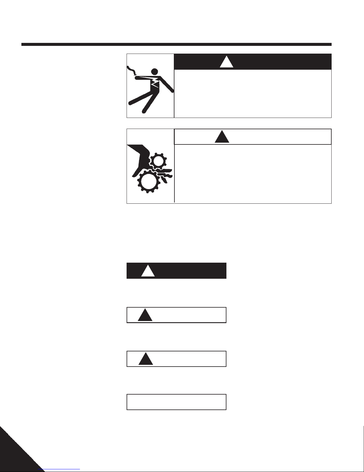
Indicates an imminently hazardous situation
which, if not avoided, will result in death or
serious injury.
Hazardous voltage.
Will cause severe personal injury, death, or property damage.
Only qualified personnel should work on or around this equipment
after becoming thoroughly familiar with this document and other
publications regarding this equipment.
Fast moving parts can be hazardous.
Contact can result in death, severe personal injury and/or substantial
property damage.
The motor operator cycles in less than 1⁄2 second. Exercise extreme
caution when operating this device. Be sure you and others are clear
of any moving parts. Do not attempt to defeat any interlocking safety
devices.
!
DANGER
▲
!
W ARNING
!
DANGER
!
W ARNING
Product
The product covered by this installation, operations and maintenance manual is the motor operator for an overhead distribution
switch with reciprocating controls.
This product is designed for an overhead distribution switch with reciprocating controls
only. It cannot be field modified for an overhead distribution switch with torsional controls. If the overhead distribution switch has
torsional controls, do not attempt to install
this product. Contact your supervisor or factory representative to secure the appropriate
motor operator.
4
Indicates a potentially hazardous situation
which, if not avoided, could result in death or
serious injury.
!
CAUTION
Indicates a potentially hazardous situation
which, if not avoided, may result in minor or
moderate injury.
Function
This product converts a manually-operated
overhead distribution switch with reciprocating controls to motor-operated. The motor operator uses an electric motor and drive
mechanism to open and close the overhead
distribution switch.
CAUTION
Used without the safety alert symbol indicates a potentially hazardous situation which,
if not avoided, may result in property damage.
P817-1187 Rev A
Page 5

1—Overview
Application/Mounting
The motor operator for an overhead distribution switch with reciprocating controls is designed for mounting on wooden utility poles.
If the utility pole is steel or concrete, mounting may be accomplished if holes can be
made in the pole or by using brackets. Contact your factory representative for details on
mounting the motor operator on steel or concrete utility poles.
!
WARNING
In areas accessible to the general public, this motor operator should
be installed with a minimum vertical height of 8 feet (2.4 meters) from
the ground to the bottom of the enclosure. If this minimum height cannot be achieved, use shields, guards, enclosures or fencing to isolate
the motor operator from the general public.
Operating Environment
The motor operator for an overhead switch
with reciprocating controls is designed for
outdoor installation and can be mounted in
direct sunlight in ambient temperatures between -40°C and +60°C.
Specifications
Electrical
• Input: 115VAC-5 amp, or
230VAC-4 amp
• Output: 12VDC-3 amp or
27.8VDC-1 amp, continuous
Mechanical
• Thrust 1200 lbs. (5300 N) @ 5" Lever Arm
• Travel: 90° movement or 5":
• Speed: 0.3 second min., 0.5 second max.
• Range: Capable of 5" to 14" control pipe displacement
• Mechanical: Life: a minimum of 1000 open/close
operations
• Connection: Couples with existing crank (1/2 inch
hole) @ bottom of reciprocating control pipe
Physical
Weight: 300 lbs (136 kg)
Dimensions: Height 50-1⁄2 inches (1280 mm)
Width 24 inches (610 mm)
Depth 19 inches (485 mm)
Enclosure Type: NEMA 4/12
P817-1187 Rev A
5
Page 6

2—Installation Notes
For future reference, use this space to make
notes specific to this unit’s installation, operation and maintenance.
Date Installed:
Model Number:
Serial Number:
RTU:
Protocol
Radio
Sensors
6
P817-1187 Rev A
Page 7

3—Customer Supplied Requirements
The following is required for installation. Be
sure to have these items on hand before
beginning installation.
Safety Equipment
• Hard hat
• Steel-toe work boots
• Appropriate eye protection per your utility’s
policy
• Other safety equipment as required by your
utility’s policies
Hardware
• Two 5⁄8 inch diameter galvanized bolts long
enough to pass through the center of the
utility pole, plus 3 inches
(75 mm)
• Four galvanized 5⁄8 inch ID/1-3⁄4 inch OD
washers
• Two 5⁄8 inch inside diameter galvanized nuts
to go with the bolts
• Two 3⁄8 inch diameter by three inch
galvanized lag screws
• One 1/2 inch x 13/4 inch bolt
• Two 1/2 inch nuts
Electronic
• Correct communications equipment applicable for this installation
• Current/voltage sensors with cables if applicable for this installation
• IBM compatible lap-top computer with appropriate software and cables for this installation
Power Supply
• 115VAC-5 amp or 230VAC-4 amp
service
• Appropriate fuse/circuit breaker
protection and power disconnect switch
with lockout provision
• Other conduit, boxes, fittings, etc. as normally used in similar installations
Electrical
• Color-coded conductors for power hook-up
per your utility’s specifications
• 1-1⁄2 inch NPT male conduit fitting
• Service/weather head for conduit
• Sufficient conduit to reach from
service/weather head to the conduit
fitting on the bottom of the enclosure
• #6 ring or spade terminals
• Suitable grounding source
P817-1187 Rev A
7
Page 8
4—Receiving & Handling
Inspect Packaging
• Upon receipt, immediately inspect packaging for signs of damage
• Start inspection with the packaging material and proceed to the equipment within
• Look for concealed damage
• If damage is found, note damage on “Bill of
Lading” prior to accepting
delivery, if possible
Note: Documentation of visible
shipping damage can determine
the outcome of any damage claim.
Notifying the carrier of concealed
damage within 15 days is essential
to resolving or minimizing unsettled claims. Immediately file
your claim and notify your factory
representative.
Unpacking
• Place shipping crate up-right on stable,
level ground near the utility pole
• Remove the top and all sides from the
shipping crate
• Leave motor operator on its pallet until
ready to install
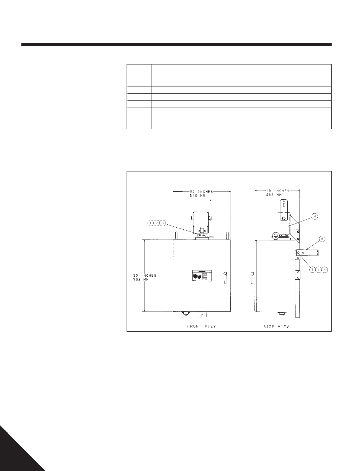
Table 1 – Parts List
Item Quantity Description
12
22
32
4 1 Right angle drive
5 2 Pole Strap
62
72
82
1
⁄2" split lock washer (stainless steel)
1
⁄2" - 13 X 1-1⁄4" long bolt (stainless steel)
1
⁄2” flat washer
1
⁄2" - 13 galvanized nut
1
⁄2" galvanized lock washer
1
⁄2" 13 x 11⁄2" galvanized bolt
Figure 1 – Parts List
Parts List
• Compare motor operator with the
illustration in Figure 1 and the parts list in
Table 1 to be sure all items have been included
• Contact your factory representative if any
parts are missing
8
P817-1187 Rev A
Page 9

4—Receiving & Handling
Components
• Become familiar with the component
names and locations shown in Figure 2
• Open the motor operator door and identify
all the items shown in Figure 2
• Match the components in the following list
with those on the motor operator:
1. Lifting eyebolts
2. Rotation limit switches
3. Enclosure heater
4. Drive casting
5. Shift handle
6. Motor operator
identification nameplate
7. Control box
8. Manual motor rotation knob
9. Manual operating handle
10. Universal RTU receptacle
11. Ground lug and conduit fitting
12. Electrical terminal block 2
13. Radio Mount (if applicable)
14. RTU Panel (if applicable)
Figure 2 – Component Location
(3)
(2)
(1)
(14)
(13)
(12)
(11)
(4)
(1)
(5)
(6)
(7)
(8)
(9)
(10)
P817-1187 Rev A
9
Page 10

5—Installation
Preparation
Step 1. — Modify Existing
Switch Handle
• Refer to Figures 3a and 3b
• Make sure overhead switch is closed
• Loosen and reposition ground strap clamp
so it is out of the way
• Remove the existing manual switch handle,
pole mount bracket and crank.
(see Figure 3a & 3b)
• Establish how high the bottom of the enclosure will be above the ground
• Cut off the control pipe 46 inches (1168
mm) higher than where the enclosure's
bottom will be
!
External parts can move suddenly and unexpectedly.
This can pose a danger to the general public.
In areas accessible to the general public, this motor operator should
be installed with a minimum vertical height of 8 feet from the ground to
the bottom of the enclosure. If this minimum height cannot be
achieved, use shields, guards, enclosures or fencing to isolate the
motor operator from the general public.
Figure 3a – Switch Handle
Before Modification
WARNING
10
Figure 3b – Switch Handle
After Modification
P817-1187 Rev A
Page 11

5—Installation
Step 2. — Drill Mounting Holes
• Refer to Figure 4
• Mark upper hole location on the utility pole
by measuring 12.75 inches (324 mm)
down from the bottom of the control pipe
and 2.5 inches (63 mm) around the pole
from the control pipe centerline. (see Figure 4).
• Mark the lower hole location on the utility
pole 34-1⁄2 inches (875 mm) below the first
mark. This second mark must also be on
the same centerline as the first hole.
• Drill two 11⁄16 inch (18 mm) diameter holes
through the utility pole where marked as
shown in Figure 4. Be sure the holes are
drilled through the centerline of the pole.
• Assemble customer supplied 5⁄8 inch diameter bolts, washers and nuts to the utility
pole
• Leave bolts sticking out of the control pipe
side of the utility pole to receive the motor
operator
Figure 4 – Mounting Holes In Utility Pole
P817-1187 Rev A
11
Page 12

5—Installation
Mounting
Step 1 — Mounting The Motor Operator
• Refer to Figure 5
• Ready lifting equipment to hoist motor operator
NOTE: Lift motor operator by lifting eyebolts only.
• Attach lifting strap, chain or cable
safety hooks/shackles to lifting eyebolts
only. Strap, chain or cable and hooks must
be able to support 300 lbs (136 kg)
• Use spreader on lifting strap, chain or
cable so the motor operator is lifted
straight upward on the lifting eyebolts
• Hoist motor operator into position on utility
pole. Slip 5⁄8 inch bolt heads and washers
through the upper tear-drop shaped hole
and the lower slot in the mounting channel
• Lower motor operator until it is
supported by both bolts
• Torque nuts on mounting bolts to 25 - 28
ft.lbs (34 - 38 N.m)
• Assemble pole straps to each side of the
motor operator mounting channel where
shown in Figure 5 using supplied
bolts, lock washers and nuts
• Form the pole straps around the utility pole
(horizontally or diagonally) and tighten the
1
⁄2 inch bolts
• Secure pole straps to the utility pole by
driving in 3⁄8 inch diameter lag screws (customer supplied)
• Remove the lifting strap, chain or cable and
lifting eyebolts from the motor operator
• Place filler caps or 3/4" bolt & rubber
washer (supplied) into threaded eyebolt
holes on enclosure
1
⁄2 inch
Figure 5 – Mounting Motor Operator
Step 2. — Attaching The
Switch Control Pipe
NOTE: Do not stand on motor operator enclosure or use it as a step.
• Verify the motor operator and the overhead
switch open the same direction, refer to Section
"Reversing Motor Rotation" if necessary.
• Verify the motor operator is in the closed position
before connecting to the closed overhead switch,
refer to section "Energizing, Exercising and Inspecting" if necessary.
• Attach crank from existing switch to lowest hole
in lever arm with a 1/2 inch x 13/4 inch bolt and
nut. Ensure free movement between crank and
lever arm. Use a second jam nut to lock the first
nut in place - see illustration.
12
P817-1187 Rev A
Page 13

5—Installation
• Insert the switch control pipe in the crank
casting. Depending on crank style, the
control pipe length may need to be shortened for proper fit. Tighten fasteners until
switch control pipe is firmly held.
• Depending on the type of crank provided
with the switch, tightening of crank piercing bolt may be required.
Checking Installation
Step 1. — Checking Installation
• Refer to Figure 6
• Disengage the motor operator’s mechanism from the drive mechanism by pulling
the shift handle out and then down into the
DECOUPLED position
(see Photograph A)
• Attach manual handle at drive connection
with clevis pin. Open overhead switch and
check for binding.
• If binding occurs, look for source of binding
and realign drive connection until manual
operation shows no signs of binding
• If the overhead switch does not open completely, increase opening range by moving
crank to lever arm connection up one bolt
hole. Control pipe will need to be shortened for proper crank fit.
• Repeat manual overhead switch rotation to
assure switch opens completely. If overhead switch still does not open completely,
increase opening range again.
• Place overhead switch back into closed position with the manual handle.
• Re-couple the motor operator mechanism
by lifting the shift handle up and pushing it
in so that the handle tabs are engaged
(see Photograph B)
• Return manual handle to its original position within enclosure.
Figure 6 – Key Components
Photo A
Shift handle
in
DECOUPLED
position
Photo B
Shift handle
in
COUPLED
position
P817-1187 Rev A
13
Page 14

6—Wiring
Wiring Guidelines
1. If low voltage and high voltage wires cross
paths, make sure the intersection is made at a
right angle.
2. To minimize noise coupling, use twisted pair
sensor wires.
3. To avoid ground loops, each motor operator
must be grounded at a single ground point.
The grounding path to earth must:
• Be permanent
• Be continuous
• Safely conduct ground fault currents that
may occur in the system to ground
through minimum impedance
• Carry no current under nor mal
conditions
!
W ARNING
Hazardous V oltage.
Contact with an energized and/or ungrounded motor operator component will result in death, severe personal injury, erratic operation of
equipment or substantial property damage.
Make sure the motor operator is properly grounded. Turn “OFF” and
lock out all incoming power sources before attempting to internally
wire or work on the motor operator.
Photo C
Grounding & Surge Suppression
Step 1. — Install Safety Ground
• Use wire gauge and type and pole ground
in accordance with your utility’s instructions or specifications
• Ground motor operator by attaching safety
ground lead between ground lug (next to
the conduit fitting) and pole ground
Step 3. — Install Surge
Suppression Devices
• Apply surge suppression devices according
to your utility’s practices
• Motor operators with the radio option have
surge suppression for the radio antenna
factory installed
• For other communication devices, surge
suppression will be required as applicable.
Power Wiring
Step 1. — Accessing Terminal
Block 2
• Open enclosure door and firmly engage
door stop mechanism
Control box
thumbscrews
Photo D
Quick
disconnect
plugs
• Note number, size, orientation and location
of quick-disconnect plugs for reinstallation
• Unplug quick-disconnect plugs
• Remove control box by lifting and pulling
forward until control box clears its mounting slots
14
• Locate and loosen control box
thumbscrews (see Photograph C)
• Rotate top of control box downward until
it rests on its stops
(see Photograph D)
P817-1187 Rev A
Page 15

6—Wiring
• Set control box in a clean, dry area where
it will not fall or be subject to damage
• Locate and loosen terminal block cover retaining screw (see Photograph E)
• Remove terminal block cover and set it
aside with the control box
• Step 2. — Preparing Power Wiring.
• Remove the plug from the conduit
fitting
• Assemble conduit per your utility’s instructions and specifications
NOTE: Enclosure conduit threads are female 1-1⁄2 inch NPT
• Run appropriate sized power wiring
through the conduit and into the
enclosure to terminal block 2
Step 3. — Wiring 115VAC Power Supply
• Refer to Figure 7
• The motor operator is factory-wired for
115VAC power
• Connect 115VAC incoming power with ring
or spade terminals as shown in Figure 7
• Replace the terminal cover on terminal
block #2 and tighten the screw
Step 3a. — Wiring 230VAC Power Supply
Photo E
Terminal
block 2 cover
Terminal
block cover
retaining
screw
Figure 7 – 115VAC
Power Connection
• Refer to Figure 8
NOTE: Move red lead on top of terminal
block 2 as shown in Figure 8.
• Move the red wire on top of terminal block
2 from the neutral terminal to
the open 115VAC terminal
• Connect 230VAC incoming power with ring
or spade terminals as shown in Figure 8
• Replace the terminal cover on terminal
block #2 and tighten the cover
retaining screw
Figure 8 – 230VAC
Power Connection
P817-1187 Rev A
15
Page 16

7—Pre-Operation Checks
Energizing
Step 1. — Reassembly
Prior T o Energizing
• Refer to Photograph F
• Place control box into mounting slots
• Reconnect all of the plugs to the
control box
NOTE: Plugs P2A and P2B can be
interchanged. See next step for location of these plugs and how to
reverse direction of the motor operator.
• Set control box voltage selector switch to
match incoming power supply
voltage (see Photograph F)
• Turn the circuit breaker on the back of the
control box to “ON” position
(see Photograph F)
• Rotate control box to the upright
position and tighten thumbscrews
(see Photograph G)
Reversing Motor Rotation
!
CAUTION
Voltage selector switch must be set properly.
Misapplied voltage will result in mis-operation and/or damage equipment
Set voltage selector switch on the back of the control box back to match incoming power
voltage.
Photo F
Voltage
selector
switch
Circuit breaker
Photo G
Control box
thumbscrews
Step 1. — Reversing
Motor Operator Rotation
Note: The motor operator is factory
set to open the overhead distribution switch by pulling down on
control pipe and pushing up on the
control pipe to close. Proceed only
if the overhead switch opens by
pushing up on the control pipe.
• Skip this procedure if the overhead switch
opens by pulling down on the control pipe.
• Refer to Photograph H
• Factory set has plugs P2A at the back,
P2B in the middle and P2C at the front
(see Photograph H)
• To reverse the motor operator:
1) reverse plugs P2A and P2B
2) Pull apart the two quick disconnect motor lead terminals and reverse the
connections (see Photograph I)
• The motor operator will now operate by
pushing up on the control pipe to open
overhead switch.
Plug P2A
Plug P2B
Plug P2C
Photo H
To reverse motor
operator, switch
plugs P2A and P2B
Photo I
Motor lead
terminals
16
P817-1187 Rev A
Page 17

8—Operation
Energizing, Exercising &
Inspecting
Step 1. — Turn On Power
• Turn the power supply “ON” at the fuse/
breaker box if applicable
• Refer to Figure 9
• Turn control box main power switch “ON”
• Status lights for “POWER” and switch
“CLOSE” will illuminate
Step 2. — Exercising Overhead
Switch
• Place local/remote switch in local
position
• Open overhead switch by pressing the
“OPEN” push-button
• Close overhead switch by pressing the
“CLOSE” push-button
• Observe status light functions:
– “OPEN” illuminated when overhead
switch is open
– “CLOSE” illuminated when overhead
switch is closed
• If status light indication is opposite overhead switch position, review “Reversing
Motor Operator Rotation” in the Pre-Operation Checks section and correct as necessary
Step 3. — Inspecting Overhead
Switch
!
DANGER
Hazardous voltage.
Electrical contact with system voltage will cause severe injury or death.
Do not exercise overhead switch while it is energized.
!
WARNING
Moving parts.
Can cause severe injury.
Do not operate motor operator until hands and clothing are clear of all
moving parts.
Figure 9 – Control Box Switches
• Cycle the overhead switch 8 to 10 times
• Thoroughly inspect overhead switch for
proper opening and closing
• If overhead switch does not fully/adequately open or close, proceed to the
section on Adjustment, and return to Step
4 below
Step 4. — Set Local/Remote
Operating Mode
• Place local/remote switch in desired position
P817-1187 Rev A
Additional Functions
Battery Test
Press and hold the “Battery Test” switch for 10
seconds. The “Low Battery Alarm” will illuminate if there is a battery problem.
Lamp Test
Press and hold the “Lamp Test” switch.
All control box lights will illuminate.
17
Page 18

8—Operation
Decoupling & Coupling
Motor Operator
Step 1. — Decoupling Motor
From Drive Casting
• Refer to Photograph J
• Decouple the motor operator by pulling out
and down on the shift handle
(see Photograph J)
• It may be necessary to release tension in
the coupling assembly by turning the
manual motor rotation knob
(see Photograph K)
• Lower and release the shift handle into the
“DECOUPLED” position
• Place the shift handle tabs into the
“DECOUPLED” slot to ensure that the motor is fully “DECOUPLED”
Step 2. — Coupling Motor
With Drive Casting
Photo J
Shift handle in
DECOUPLED
position
Photo K
Manual motor
rotation knob
• Refer to Photograph L
• Couple the motor operator by pulling out
and up on the shift handle
(see Photograph L)
• It may be necessary to align the
coupling assembly by turning the
manual motor rotation knob
(see Photograph K)
• Raise and press the shift handle into the
"COUPLED" position
• Place the shift handle tabs into the
“COUPLED” slot to ensure that the motor
is fully coupled
Step 3. — Exercising The Motor
While Decoupled
• Decouple motor operator as detailed in
Step 1 above
• Exercise the motor by pushing either the
“OPEN” or “CLOSE” push-button switches
• The motor will run until power is turned
“OFF”
• Stop the motor by flipping the control box
main power switch to “OFF”
• Turn the control box main power switch to
“ON”
• Couple motor operator as detailed in Step
2 above
Photo L
Shift handle
in
COUPLED
position
18
P817-1187 Rev A
Page 19

8—Operation
Manual Operation
Step 1. — Manual Switch Operation
• Decouple the motor as outlined in the
Decoupling & Coupling Motor Operator
section
• Refer to Figure 10
NOTE: Removing the manual operating handle from the enclosure
activates a safety device that
makes the motor operator inoperable until the drive mechanism has
been decoupled, or the manual operating handle is returned to its
storage position. Do not attempt to
defeat this safety device.
• Remove the manual operating handle from
its cradle in the bottom of the enclosure
(see Photograph M)
• Attach the manual operating handle to the
overhead switch control pipe by using the
bent arm pin and cotter pin as shown in
Figure 10
• Manually operate the overhead switch as
directed by the switch manufacturer
Photo M
Manual
operating
handle
!
WARNING
Hazardous voltages and high speed moving parts.
These can cause death, serious personal injury or damage equipment.
Lock out power at circuit breaker/fuse box and turn control box main
power switch “OFF” before attempting to manually operate this unit.
P817-1187 Rev A
Figure 10 – Manual Operating Handle
Manual operating handle removed from enclosure and attached to switch control pipe with bent arm pin and cotter
pin
19
Page 20

8—Operation
Remote Operation
The switch can be operated from central
control via a communication link to the
RTU, allowing for remote configuration, diagnostics, and operation. Refer to the
SCADA system instruction manual for specific instructions. Regardless of the type or
make of the SCADA system, the user must
place the Remote/Local switch in the "Remote" position to allow remote operation.
Photo N shows typical Motor Operator with
RTU installed.
The Universal RTU Receptacle shown in
Photo O allows modular connection to an
RTU and communication back to central
control. Refer to supplemental drawing
SD817-1149 for signal pin outs and remote operation relay specifications. The
following controls and diagnostics are provided.
Remote Status
• Remote/Local switch position indicator.
Open Status
• Overhead switch position indicator.
Close Status
• Overhead switch position indicator.
Low Battery Alarm
• Low battery indicator.
Battery Charger Status
• Battery charger present indicator. Also indicates AC supply is present.
Battery Test
• Remote battery test control.
Remote Open
• Remote open control.
Remote Close
• Remote close control.
Photo N
Typical RTU Installation
20
Photo O
Universal RTU Receptacle
P817-1187 Rev A
Page 21

9—Adjustment
IMPORTANT NOTICE
The limit switches adjust the motor
operator for normal opening and
closing. Limit switches will not
compensate for an improperly adjusted overhead switch.
Limit switch adjustment on this
motor operator is normally not
necessary. The motor operator is
factory set for 90° of rotation. If the
overhead switch fails to close and
open completely with the factory
set 90° rotation travel, follow the
steps below.
Limit Switches
Step 1.— Adjusting Limit Switches
• Refer to Figure 11
• Turn off the control box main power switch
before making any limit switch adjustment
• The “OPEN” limit switch controls the
“OPEN” adjustment
• The “CLOSE” limit switch controls the
“CLOSE” adjustment
• Loosen thumbscrews (see Photograph P)
and move the limit switches as shown in
Figure 11 to increase or decrease the
amount of rotational travel as required for
proper overhead switch operation
• Tighten limit switch thumbscrews before
testing rotational travel
• When finished adjusting the limit
switch(es), make certain the control box
main power switch is “ON”
NOTE: If the motor operator’s rotation direction has been reversed
(as described in — Pre-Operation
Checks, Reversing Motor Rotation)
limit switch controlling functions
are reversed: “CLOSE” is the open
limit switch and “OPEN” is the
closed limit switch.
"CLOSE"
Limit switch
thumbscrew
"OPEN"
Limit switch
thumbscrew
Figure 11 – Adjusting Limit Switches
Note: Figure 11 indicates limit switch adjustments
for factory set clockwise rotation (non-reversed in-
Photo P
P817-1187 Rev A
21
Page 22

10—Maintenance
Enclosure Exterior
The enclosure has been factory painted to
deliver years of protection. If the paint finish
has been damaged, touch-up affected spots
with ANSI 61 gray enamel (Wiegmann Enclosure Company catalog number WAGSE). Be
careful not to paint over enclosure door
handle, drive casting or other parts that would
be adversely affected by painting.
Do not paint over warning and other safety
related exterior labeling. If replacement labels
are needed, contract your factory representative
Remove tree branches and any other objects
that may come in contact with the motor
operator and/or the overhead switch control
pipe mechanism.
Batteries
The sealed, maintenance-free lead acid gel
batteries furnished with the motor operator
are rechargeable 26 amp-hour, 12 volt DC.
Test these batteries once a month by pressing
the battery test button for 10 seconds. The low
battery alarm will light if the batter ies are not
fully charged. This test can be perfor med and
monitored remotely.
If the batteries have a low charge or are 3
years old, replace both with B & B Battery part
number BP26-12, with fast-on connectors, or
Powersonic Battery part number PS-12260F
with fast-on connectors.
Light Bulbs & Control
Box Status Lights
Both the enclosure light and control box status
lights should come “ON” when the enclosure
door is opened. If the enclosure light does not
come “ON,” replace it with a Chicago Lamp
Part Number 308. If the control box status
lights do not come “ON” when the door is
open, then perform a lamp test. Lamp test
button is on the front of the control box. When
pressed, all status lights should come “ON.” If
some or all status lights do not come “ON,”
contact your factory representative.
Transmission Lubricant
The transmission is sealed, but a small
amount of lubricant may seep out to the
bottom of the enclosure or onto the batteries.
Minor seepage is not a problem. It may be
removed with a shop towel and then disposed
of at an appropriate waste facility in accordance with your local utility’s regulations.
Non-Functioning Motor
Operator
If the motor operator will not function, go to
Trouble Shooting Guide and follow the suggested corrective actions. If the motor operator still does not function, contact your factory
representative.
Battery Storage Life
Self-discharge characteristics of these batteries make it imperative they be charged after 6
months of storage. Otherwise per manent loss
of capacity might occur from sulfation.
22
P817-1187 Rev A
Page 23

11—Trouble Shooting
The following table presents the most common symptoms, their possible cause(s) and likely corrective action(s). These do not cover all
possible problems. If you are unable to correct a problem using this trouble shooting guide, contact your factor y representative.
Table 2 – Trouble Shooting Guide
Symptom Possible Cause(s) Corrective Action(s)
Motor operator a) Power status light not on. a) Turn on power.
will not run. b) Manual operating handle is not inside enclosure. b) Place manual handle in space provided.
c) Motor locked rotor breaker is tripped c) Turn off power switch; reset locked
(on back of control box). rotor breaker. Turn on power switch.
d) Remote/local switch in remote position. d) Place remote/local switch to local position.
e) Battery charge below 23 volts e) Recharge or replace batteries as needed
Motor will run, a) Decoupling handle is down. a) Move decoupling handle to coupled position.
but overhead b) Piercing bolt is not tightened completely. b) Tighten piercing bolt until no threads
switch will are showing.
not turn.
The overhead switch a) Limit switch improperly set. a) Adjust limit switch; refer to Section "Adjustment".
is not fully open or b) Loose hardware b) Tighten hardware
fully closed.
Can not decouple a) Excessive wrap-up on control pipe. a) Pull out shift handle and turn manual
drive mechanism. b) Inadequate limit switch setting. motor rotation knob to release tension.
b) Adjust limit switch position
Moisture in a) Disconnected power leads to heater a) Inspect and reconnect if needed
enclosure b) Faulty heater thermostat b) Contact factory representative
c) Burned out heating element c) Contact factory representative
Low Voltage a) Charger off a) Control box rear circuit breaker switched off.
Alarm b) Charger off b) AC supply not present; refer to "Power Wiring" Section
c) Batteries discharged c) Repair /replace batteries
Motor Operator not a) Local/Remote switch a) Place Local/Remote switch in "Remote" position.
responding to b) Control Box/Connection problem. b) If the control box/ connections are not functioning
remote commands Verify control box remote functions by simulating inputs/ contact factory representative.
outputs at Universal RTU receptacle refer to
supplemental drawing SD817-1149 (located in side
pouch). Output can be measured with a DVM.
Inputs can be simulated by shorting corresponding receptacle pins.
c) RTU connection problem. Ver ify signal connections c) If RTU connections problem exists, contact factory
to RTU by measuring outputs with DVM and simu- representative.
lating inputs at the RTU refer to supplemental drawings
d) RTU/configurations problem. Ver ify RTU operation using d) If RTU is not functioning, contact RTU manufacturer.
local pc connection refer to RTU manuals.
e) Communications/configuration problem. Verify communications e) If Communications are not functioning, contact
refer to communication manuals communications representative.
P817-1187 Rev A
23
Page 24

®
POWER
SYSTEMS, INC.
© Copyright 1999, A.B. Chance Company
210 North Allen Street, Centralia, MO 65240-1395
Printed in U.S.A.
24
P817-1187 Rev A
 Loading...