

Page 1

Instructions
for the preparation
and use of
®
Protective Grounding-Set
Tester
Catalog No. C403-3220 (115/120V)
and PSC4033220003 (230V)
WARNING
!
Select actual work-site values for system-fault current, fault duration and permissible maximum-worker-body
current before attempting to set grounding jumper acceptable limits.
Failure to select actual system-fault current, fault duration and permissible maximum-worker-body current
may result in personal injury or death.
These instructions do not claim to cover all details or variations in equipment, nor to provide for all possible conditions to be met with
concerning installation, operation, or maintenance of this equipment. If further information is desired or if particular problems are
encountered which are not suciently covered in this guide, contact A. B. Chance Company.
NOTE:
Because Hubbell has a policy of continuous product improvement, we reserve the right to change design and specications without notice.
© Copyright 2016 Hubbell Incorporated, 210 N. Allen, Centralia, MO 65240 Printed in USA
Page 1 of 20
P403-3222 Rev. K 4/18
Page 2

TABLE OF CONTENTS
FUNCTIONAL DESCRIPTION ...............................................................................................3
FEATURE DESCRIPTION .......................................................................................................3
SELF TEST PROCEDURE .......................................................................................................6
THRESHOLD PROGRAMMING ............................................................................................7
1. Threshold Derivation ................................................................................................7
2. Changing the Threshold ............................................................................................8
TEST SETUP .............................................................................................................................9
GROUND SET TEST PROCEDURE .....................................................................................10
GROUND SET TROUBLESHOOTING WITH PROBES .....................................................11
EXPECTED GROUND SET RESISTANCE ..........................................................................11
ERROR MESSAGES ..............................................................................................................12
APPENDIX A
THEORY OF RESISTANCE THRESHOLD DETERMINATION ............................12
P403-3222 Rev. K 4/18
Page 2 of 20
Page 3

FUNCTIONAL DESCRIPTION
The PROTECTIVE GROUNDING SET TESTER uses a 5 volt direct current (dc) source to measure resistances in grounding sets. Output current through the grounding set is limited to a maximum of 10 amps by
an internal current limiting resistor. The tester switches the 5 volt power supply on, makes a measurement,
and switches the power off again for a minimum of 500 milliseconds.
The tester uses a 4 wire resistance measurement approach to obtain accurate resistance measurements. The
measurement system is auto ranging to give +/-1% accurate resistance measure from 1 µΩ* to 6.5 Ω.
FEATURE DESCRIPTION
The following list of features are referenced with number 1 - 19, and the location of the feature is shown on
Figure 1.
1. Test Probes
Probes are used in troubleshooting mode to locate high resistance area of the ground set.
2. Instructional Video P403-3223
Shows how to use the Protective Ground Set Tester. The videotape is not a substitute for this Instruc-
tion Manual. Thoroughly read and understand these instructions before using the Tester.
3. Fixed Input Connections
When the ‘INPUT SELECT’ switch is in the xed position. The resistance measurement shown will
be the value of resistance from one xed connection through the ground set to the other xed connection.
4. Power Entry Module
Main power switch illuminates when power to the tester is on, and includes the fuse holder
compartment.
5. Preset Resistance Threshold
This number, shown on the display, is the pass/fail resistance threshold used to light the pass or fail
LEDs. There is a different resistance threshold for each cable size. The ‘<’ symbol displayed means
less than. For example, when ‘<3.333’ (mΩ**) is displayed, it means that a ground set resistance
which is less than 3.333 mΩ** will light the pass LED.
6. Measured Ground Set Resistance
When the ‘INPUT SELECT SWITCH’ is in the ‘FIXED’ position. The value shown will be the re-
sistance measured from one xed connection (3) through the ground set to the other xed connection
(3). When the ‘INPUT SELECT SWITCH’ is in the ‘PROBE’ position. The value shown will be the
resistance measured between the probe contact points.
7. Selected Cable Size
Indicates size of cable under test. This must be changed for each new size cable used.
*1 µΩ (1 micro ohm) = 0.000001 ohm
** mΩ (milli ohm) = 0.001ohm
Page 3 of 20
P403-3222 Rev. K 4/18
Page 4

8. Continuous Test Switch
When switched to the ‘ON’ position, the ground set tester will continuously make measurements at
the rate of 1 per second. When switched to the ‘OFF’ position, the ground set tester will hold the last
measurement made.
9. Fail LED (Red)
This LED will light whenever the last measurement is greater than the preset resistance threshold. It
will also turn off to indicate a new measurement is being made.
10. Cable Size Switch
Used to select the size of cable to be tested. (#2, 1/0, 2/0, 4/0)
11. Pass LED (Green)
This LED will light whenever the last measurement is less than the preset resistance threshold. It will
also turn off to indicate a new measurement is being made.
12. Power Cord
For connection to AC power supply.
13. Probe Input
When the ‘INPUT SELECT’ switch is in the ‘PROBE’ position, the resistance measurement shown
will be the value of resistance between probe contact points.
14. Input Select Switch
Allows selection of measurement input between the probes or the xed connections to the ground
set.
15. Single Test Switch
Causes the Ground set tester to make a single resistance measurement and hold the value.
16. Attachment Studs
These copper studs are threaded into the xed connection (3), and the ground set clamps can then be
attached to the studs.
17. Elbow adapter
Used to adapt ground set with grounding elbow to threaded xed connection. 15kV elbow adapter
(C403-3449) is available as an option.
18. Grounded Parking Stand Adapter
Used to adapt ground set with grounded parking stand to threaded xed connection. Parking stand
adapter (T403-3159) is available as an option.
19. Self Test Cable
Used for testing the functionality of the Protective Ground Set Tester.
P403-3222 Rev. K 4/18
Page 4 of 20
Page 5
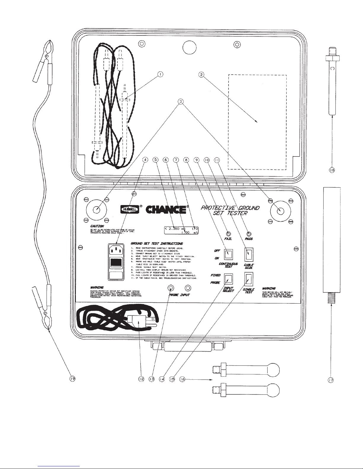
Figure 1: Front Panel of Protective Ground Set Tester Showing Feature Location
Page 5 of 20
P403-3222 Rev. K 4/18
Page 6

SELF TEST PROCEDURE
The operation of the Protective Ground Set Tester can be veried using the Self Test Cable included with the
tester. It is not designed to test accuracy.
1. Place the tester on a table of convenient height and plug it into an AC outlet, 110 (Cat. No. C403-
3220) or 220 (Cat. No. PSC403-3220003) VAC.
2. Thread the attachment studs into xed connection inputs.
3. Securely connect Self Test Cable to the attachment studs.
4. Turn on the unit. The power switch will illuminate when the power is on.
5. Place the ‘INPUT SELECT’ switch in the ‘FIXED’ position.
6. Place the ‘CONTINUOUS TEST’ switch in the ‘OFF’ position.
7. Press the ‘SINGLE TEST’ switch.
8. The display will show the measured resistance of the self test cable on line 2 of the display. The
resistance measured should be between 3.0 and 7.5 mΩ**. If the measured resistance is outside these
values, retighten the ball studs and check to make sure that the self test cable has good electrical connections. After retest, if the measured resistance is still not between 3.0 and 7.5 mΩ**, discontinue
use of the tester. The Self Test Cable is not designed with tight tolerances for accuracy testing.
Note that the thresholds and pass/fail LEDs will function during the self test but do not pertain to the self
test.
**mΩ (milliohm) = 0.001 ohm
P403-3222 Rev. K 4/18
Page 6 of 20
Page 7

THRESHOLD PROGRAMMING
1. Threshold Derivation
The resistance threshold (R
by the maximum current (I
shows the preset values used for four sizes of cable. The ground set tester comes from the factory
with (R
) based upon (V
THR
values for Copper Grounding Jumper Assemblies for 25 ft assemblies per ASTM 2249-03 (2009).
) is calculated by dividing the voltage allowed across the man (V
THR
) the protective ground set can withstand for the 15 cycles. Table 1
MAX
) = 60V which sets the (RTHR) at or below the Pass/Fail Resistance
MAN
MAN
)
CABLE SIZE
15 CYCLE CURRENT WITHSTAND CAPABILITY*
#2
1/0
2/0
4/0
* ASTM F855 standard specications for temporary grounding systems.
Table 1: Withstand Current Capability of Various Cable Size
V
R
I
= MAXIMUM CURRENT WITHSTAND CAPABILITY
MAX
V
= VOLTAGE ALLOWABLE ACROSS THE MAN
MAN
R
= MAXIMUM RESISTANCE ALLOWED FOR GROUND SET
THR
THR
=
I
MAN
MAX
14500 A
21000 A
27000 A
43000 A
The above method gives a suitable resistance threshold as long as available system fault current is below 15 cycle current withstand capability. See Appendix A for detailed theory of threshold determination.
It may be necessary to reprogram the threshold level if the preset level does not t the utility conditions.
The Safety Department of the using utility MUST select actual work-site values for system-fault current, fault duration and permissible maximum-worker-body current before attempting to set grounding
jumper acceptable limits to assure against personal injury, death or property damage. See appendix A.
Failure to select actual system-fault current, fault duration and permissible maximum-worker-body current may result in personal injury or death.
ASTM F2249 is the standard to go by when testing Ground Sets; the maximum values of Pass/Fail listed
supersede all others. Always use the most recent version as released by ASTM.
CAUTION
!
WARNING
!
Page 7 of 20
P403-3222 Rev. K 4/18
Page 8

Figure 2: Template of Switches When Changing the Threshold
2. Changing the Threshold
1) Turn off the Ground Set Tester.
2) Place the ‘CONTINUOUS TEST’ switch in the ‘OFF’ position.
3) Hold down the ‘CABLE SIZE’ and the ‘SINGLE TEST’ switches simultaneously. Power
up the unit. The display should read ‘THRESHOLD CHANGE MODE’. Release the two
switches. After three seconds, the display switches to ‘VOLTAGE ACROSS MAN AL-
LOWED 60V’.
4) Refer to Figure 2. The voltage displayed on the second line will be the voltage across the
man used to calculate the maximum values for the thresholds. This voltage can be adjusted
using the ‘CABLE SIZE’ and the ‘CONTINUOUS TEST’ switches as described in 5 & 7.
5) Select and underline the number to be changed by using the ‘CONTINUOUS TEST’ switch.
6) Use the ‘CABLE SIZE’ switch to change the number of the voltage that is underlined. The
number will increase to 9 and then change back to 0. The number on the left will change
between 0 and 2.
7) When the desired voltage is displayed, press the ‘SINGLE TEST’ switch. If you enter an
incorrect voltage, start again from Step 1.
P403-3222 Rev. K 4/18
Page 8 of 20
Page 9

TEST SETUP
Figure 3 shows the test setup required to test a protective ground set. The protective ground set under test
must always be connected between the xed connection connections regardless of the mode of testing. The
ground set carries the test current from one xed input to the other during testing. Without the ground set,
the resulting open circuit prevents the resistance measurement. If the ground set is left unconnected and
the ‘INPUT SELECT’ is in the ‘FIXED’ position, the display will read ‘OVER RANGE’ after a test. If the
ground set is left unconnected and the ‘INPUT SELECT’ is in the ‘PROBE’ position, the display will be erratic. The erratic display is unpredictable and does not indicate resistance.
Figure 3: Ground Set Testing Setup
Page 9 of 20
P403-3222 Rev. K 4/18
Page 10

GROUND SET TEST PROCEDURE
Use the Self Test Procedure to verify operation of the Ground Set Tester before testing Ground Sets.
1. Place the tester on a table of convenient height and plug it into a nominal 120/240V AC outlet.
2. Thread the attachment studs into the xed connection inputs.
3. Securely connect the Grounding Set to be tested to the attachment studs. A low resistance connection
must be maintained while testing the ground set. (Figure 3 shows typical test setup.)
4. Turn on the unit. The power switch will illuminate when the power is on.
5. Use the ‘CABLE SIZE’ switch to select the cable size being tested. The cable size is displayed at the
end of the rst line of the display.
6. Place the ‘INPUT SELECT’ in the ‘FIXED’ position.
7. Place the ‘CONTINUOUS TEST’ switch in the ‘OFF’ position.
8. Press the ‘SINGLE TEST’ switch.
9. The display will show the measured resistance between xed connections on line 2 of the display
in mΩ.** When used in xed mode the resistance displayed includes the contact resistance of the
connection studs to the ground set. The red light will illuminate if the ground set resistance is above
the preset threshold shown on line 1 of the display (see notice below). The green light will illuminate
if the ground set resistance is below the preset threshold. NOTE: Ground sets to be used in parallel
with the worker must pass the preset threshold resistance. Ground sets not used in parallel with the
worker must meet the expected resistance for the cable size and length. Refer to Section “EXPECTED GROUND SET RESISTANCE” for Ground Sets not covered by preset threshold.
**mΩ (milli ohm) = 0.001 ohm
WARNING
!
Chance protective ground set tester is not designed nor recommended for detecting cable aws. Problems with the cable, away from the ferrule exit area, are often intermittent in nature.
NOTICE
If the ground set fails (red light) there are two possibilities.
1. The ground set has a problem. Use probes to identify the high resistance section. See section
GROUND SET TROUBLESHOOTING WITH PROBES.
2. Cable is improperly sized for the application (AWG or length). See Appendix A for maximum
resistance determination.
P403-3222 Rev. K 4/18
Page 10 of 20
Page 11

GROUND SET TROUBLESHOOTING WITH PROBES
The following sections describe how to use the probes in troubleshooting a ground set. Using the probes in
this mode, the high resistance areas of the ground set can be identied.
1. Place the tester on a table of convenient height and plug it into a nominal 120/240V AC outlet.
2. Thread the attachment studs into the xed connection inputs.
3. Connect the Grounding Set to be tested to the attachment studs. A low resistance connection must be
maintained while testing the ground set. Figure 3 shows typical test setup.
4. Turn on the unit. The power switch will illuminate when the power is on.
5. Use the ‘CABLE SIZE’ switch to select the cable size being tested. The cable size is displayed at the
end of the rst line of the display.
6. Place the ‘INPUT SELECT’ in the ‘PROBE’ position.
7. Place the ‘CONTINUOUS TEST’ switch in the ‘ON’ position. This causes the ground set tester to
repeatedly make measurements at a rate of about 1 per second.
8. In this mode the display will show the resistance across the part(s) of the ground set to which
the probes are connected. Start from one end of the ground set. Take resistance readings between
attachment stud and clamp body, clamp body to cable ferrule and cable ferrule to cable ferrule. Repeat
test on opposite end.
9. The display will show the measured resistance from one probe to the other when contacting the ground
set (on line 2 of the display in mΩ). The red light will illuminate if the ground set resistance is above
the preset threshold shown on line 1 of the display. The green light will illuminate if the ground set
resistance is below the preset threshold.
WARNING
!
Chance protective ground set tester is not designed nor recommended for detecting cable aws. Problems with the cable, away from the ferrule exit area, are often intermittent in nature.
EXPECTED GROUND SET RESISTANCE
The resistance through a Ground Set will be equal to the resistance of the cable itself and the resistance
of the cable clamps and connections to the cable. The resistance of the cable is found by multiplying the
resistance per foot by the number of feet of the cable. Table 2 supplies the resistance per foot for various
cable sizes. The cable clamps and connections should be less than 0.16 mΩ*. Since there are 2 clamps
0.32 mΩ* must be added for the clamps and connections. Pass/Fail resistance values for copper grounding
jumper assemblies can also be found in Table 2 of ASTM F2249.
For example, the expected resistance for a 32 foot 1/0 Ground Set will be less than
1.05 x 32 ft x + 0.32 mΩ = 3.61 mΩ**
0.098 mΩ/ft
(See chart below)
CABLE
SIZE
4/0
3/0
2/0
1/0
#1
#2
mΩ** PER
FOOT
[11]
Table 2:
** mΩ (milliohm) = 0.001 ohm
* Derived from ASTM F2249 Standard.
0.049
mΩ
0.062
mΩ
0.078
mΩ
0.098
mΩ
0.123
mΩ
0.156
mΩ
Resistance per foot for various sizes of grounding cable
Page 11 of 20
P403-3222 Rev. K 4/18
Page 12
ERROR MESSAGES
CALIBRATE ERROR
The calibration factors have been corrupted. New calibration factors must be generated. Return to
factory for repair.
COP ERROR
Computer Operating Properly Error has occurred. A problem has occurred with the power supply, its
connections or an electronics failure. Return to factory for repair.
WARNING
!
It is the responsibility of the user to establish and maintain a maximum resistance threshold for the protective ground set to provide a safe working environment.
APPENDIX A: THEORY OF RESISTANCE THRESHOLD DETERMINATION
Although substantial research has been conducted to determine the reaction of the human body to various
levels of current, no single value can be given as a safe level for all situations. Research has determined that
the body’s reaction is dependent upon the time duration as well as the magnitude of the current ow [1], [2],
[8]. Other variables to consider are: the protective grounding method employed [3], the fault current available [4], the assumed body resistance of the protected worker [1], [5] along with his weight [3] and the level
of protection being sought by the user. Ultimately the safety department of the using utility must give due
consideration to the variables which affect the degree of worker safety which that utility desires to achieve.
Values of each variable may differ from utility to utility, or even from work site to work site. Once the variables are dened, the equations discussed below can be used to establish a maximum resistance value for
protective grounds issued to workers for use in a predened area.
For example, a nearly equipotential zone can be created by placing a protective ground in parallel with the
worker at the work site [4]. The allowable resistance of the protective ground can be higher for low values
of available fault current than for very large values. Also, fast backup circuit protective devices remove the
body current quicker, allowing a somewhat higher body current to ow and still achieve a level of protection. Many standards and reference literature use 1,000 ohms as the worker’s body resistance [3]. While this
may be not be totally correct, it provides a basis for calculations.
Charles Dalziel, a noted researcher, has published charts which are widely used in the utility industry today
[1], [2], [3], [4]. He determined statistically that the average perception current, the least current detectable
by the body, to be 1.2 milliamperes and the average let-go threshold to be 9 milliamperes [1], [6]. He further determined that 99.5% of those receiving shocks will not go into heart brillation if the shock current,
for a specied duration, is below the value calculated by Equation 1. [1], [3], [9]:
I = K/(√t) Eq. 1
Where:
I = Current owing through body’s chest cavity, in milliamperes
t = Duration of current ow, in seconds
K = A constant related to the electric shock energy
116 for a 110 lb. man or,
157 for a 154 lb. man or,
165 for a 165 lb. man
Possible ventricular brillation thresholds, with time dependency, may occur above:
0.03 second shock 1,000 milliamperes
3.00 second shock 100 milliamperes
P403-3222 Rev. K 4/18
Page 12 of 20
Page 13
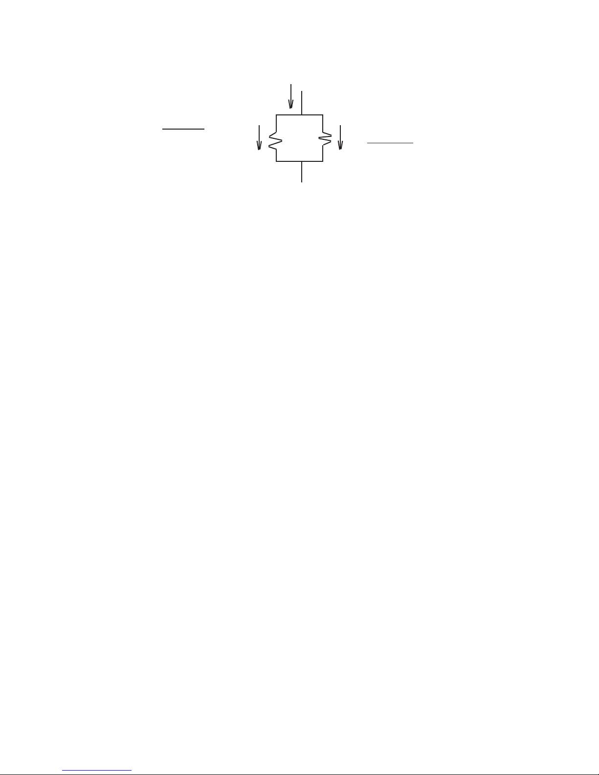
Figure 1 illustrates a parallel protective grounding scheme is used [4], [10], the current ow through the
worker is:
Fault
Current
Man Protective
Jumper
Current & Current &
Resistance Resistance
Figure 1
Im = If · [Rj/(Rj + Rm)]Eq. 2
Where:
Im = Current through the man, in amperes
If = Available fault current at the work site, in amperes
Rj = Resistance of the parallel jumper, in ohms
Rm = Resistance of the worker, in ohms
Equation 2 can be rearranged to calculate the maximum jumper resistance, for a given set of conditions.
Rj = Rm · [Im / (If - Im)]Eq. 3
Example 1:
Assume:Rm = 1,000 ohmsK = 157
If = 1,000 Amp.t = .25 Sec.
I
= 314 milliamperes, brillation threshold (from Eq. 1)
max
With 3:1 safety margin:
Rj = 100 milliohms for any parallel protective ground length (Eq. 3 divided by 3)
Some utilities, in order to provide a margin of safety in the assumptions used, for their own circumstances,
may desire to limit the maximum voltage drop across the worker to 100 V. If this is the desired approach,
equation 4 provides the limiting body current value.
Im = Vm / RmEq. 4
For the same worker as dened in Example 1
Im = 100 V. / 1,000 ohm = 100 milliamperes (from Eq. 4)
Rj = 100 milliohm, for any parallel protective ground length.
(from Eq. 3)
Page 13 of 20
P403-3222 Rev. K 4/18
Page 14

For each multiple increase in current either the maximum calculated protective ground resistance must be
divided by the multiple or a new calculation must be made, to reduce the protective resistance accordingly.
For multiples of the 1,000 Amp. fault current given above:
Fault Current Multiplier Maximum Resistance
2,000 2 50 milliohms
5,000 5 20 milliohms
10,000 10 10 milliohms
Results of calculations illustrating the body current level, below which 99.5% of the affected workers will
not experience heart brillation, is shown in Chart 1 and Graph 1. This chart is based upon C.F. Dalziel’s
research and widely used industry values. Calculations were made using equation 1, with the variable being
time duration of current ow. Chart 2 and Graph 2 illustrate the maximum allowable resistance of the protective ground, based upon the constraint that the maximum voltage drop across the man will never exceed
100 volts, at fault current level below the selected value. Equations 3 and 4 were used, the variable being
the fault current available. These charts and graphs are presented for information only.
The appropriate department of the using utility MUST dene the method and level of protection they wish
to use. The values for the variables can then be dened for that utility. See the sample calculation on page
16.
P403-3222 Rev. K 4/18
Page 14 of 20
Page 15

BIBLIOGRAPHY:
[1] Dalziel, C.F., THE EFFECTS OF ELECTRIC SHOCK ON MAN, IRE Transactions
on Medical Electronics (PHME-5), May 1956
[2] Dalziel, C.F. and Lee, W.R., LETHAL ELECTRIC CURRENTS, IEEE Spectrum,
Feb. 1969, pp 44-50
[3] IEEE GUIDE FOR SAFETY IN AC SUBSTATION GROUNDING (ANSI/IEEE
Std. 80-1986)
[4] Watson, Howard, PERSONAL PROTECTIVE GROUNDING, Facilities Instructions,
Standards, & Techniques, Volumes 5-1, United States Department of the Interior,
Bureau of Reclamation, Denver, Colorado, Jan. 1993
[5] Dalziel, C.F., THRESHOLD 60-CYCLE FIBRILLATING CURRENTS, AIEE Trans-
actions, vol 79, part III, 1960, pp 667-673
[6] Dalziel, C.F. & Massoglia, F.P., LET-GO CURRENTS AND VOLT-VOLTAGES,
AIEE Transactions, vol 75, part II, 1956, pp 49-56
[7] Dalziel, C.F., ELECTRIC SHOCK HAZARD, IEEE Spectrum, Feb. 1972, pp 41-50
[8] Effects of Current Passing Through The Human Body, International Electrotechnical
Commission (IEC) Publication 479, 1974
[9] Lee, W.R., DEATH FROM ELECTRICAL SHOCK, Proceedings of the IEEE, vol
113, no. 1, Jan. 1966, pp 144-148
[10] King, C.C., TECHNICAL CONSIDERATIONS IN PROTECTIVE GROUNDING
AND JUMPERING, A.B. Chance Co. bulletin no. 9-8001 (Rev. 1-84 CCG 5M)
[11] RUBBER-INSULATED WIRE AND CABLE FOR THE TRANSMISSION AND
DISTRIBUTION OF ELECTRICAL ENERGY, ICEA Publication No. S-19-81
(Sixth Edition)/NEMA Standards Publication No. WC3-1992. Revised Feb. 1994,
Table 2-18, Part 2, Page 19.
Page 15 of 20
P403-3222 Rev. K 4/18
Page 16

SAMPLE DEVELOPMENT OF CHART
WARNING
!
The following is only for illustrative purposes. Actual fault current, fault duration and permissible maximum worker current MUST be determined for the specic power system on which the grounding sets
are to be used.
Failure to select actual system fault currents, fault durations and permissible maximum worker current
may result in personal injury and death.
Assumptions:
Workers weight and body resistance = 165 lbs. and 1,000 ohms
Maximum available fault current, at using locations = 12,000 Amp. RMS
Back up breakers maximum operation time = 20 cycles (.333 sec.)
Utility’s Accepted level of safety:
V
worker max
I
worker max
= 100 Volts
= 0.100 ampere = 100 milliampere (from Eq. 4)
Maximum parallel jumper resistance allowed: (from Eq. 3)
Rj = 1,000 ohms X (.1 Amp. / (12,000 Amp. - 0.1 Amp.)) = 8.3 milliohm
As check on margin of safety (from Eq. 1)
I
brillation threshold
= 165 / √.33 sec. = 288 milliamp
The 8.3 milliohm value represents the maximum value of protective ground resistance allowed. This value
should be clearly printed on an appropriate size paper and placed in the lid of the tester, under the protective
cover provided. This value now represents the maximum safe level of resistance for any protective ground
to be placed in parallel with a worker in the previously dened work areas.
P403-3222 Rev. K 4/18
Page 16 of 20
Page 17

Chart 1 | Chart 2
|
| The Maximum Voltage across the man
will be limited to 100V AC if the maximum
99.5% of Workers Will Not Experience Heart jumper resistance is limited to the value
Fibrillation At Currents & Durations Below: | associated with the selected maximum
(Based Upon C.F. Dalziel’s Research) | fault current available
--------------------------------------------------------------------- --------------------------------------
Assume: 154 Lb. Man @ 1,000 ohm resistance | Maximum Rj
Ifault Maximum
| (Amp.) (Milliohm)
|
Maximum Jumper Resistance | 2000 50.0
time Iman (mohm) @ | 4000 25.0
(cycles) (mA) Available Fault Current | 6000 16.7
--------------------------------- | 8000 12.5
1000 5000 10000 | 10000 10.0
| 12000 8.3
2 860 861 172 86 | 14000 7.1
3 702 703 140 70 | 16000 6.3
4 608 608 122 61 | 18000 5.6
5 544 544 109 54 | 20000 5.0
6 496 497 99 50 | 22000 4.5
7 460 460 92 46 | 24000 4.2
8 430 430 86 43 | 26000 3.8
9 405 406 81 41 | 28000 3.6
10 385 385 77 38 | 30000 3.3
11 367 367 73 37 | 32000 3.1
12 351 351 70 35 | 34000 2.9
13 337 337 67 34 | 36000 2.8
14 325 325 65 33 | 38000 2.6
15 314 314 63 31 | 40000 2.5
16 304 304 61 30 |
17 295 295 59 29 |
18 287 287 57 29 |
19 279 279 56 28 |
20 272 272 54 27 |
21 265 265 53 27 |
22 259 259 52 26 |
23 254 254 51 25 |
24 248 248 50 25 |
25 243 243 49 24 |
26 239 239 48 24 |
27 234 234 47 23 |
28 230 230 46 23 |
29 226 226 45 23 |
30 222 222 44 22 |
Page 17 of 20
P403-3222 Rev. K 4/18
Page 18

700
600
500
400
Maximum Protective Ground Resistance
(From Dalziel's Equation)
Resistance (milliohms)
300
200
100
5 10 15 20 25 30
Time (cycles)
Graph 1
This chart is based upon C.F. Dalziel's research and widely used industry values. Calculations were made using equation 1 with
the variable being time duration of current ow.
P403-3222 Rev. K 4/18
Page 18 of 20
Page 19

35
30
25
20
Maximum Protective Ground Resistance
Vman = 100 V. Max.
15
Resistance (milliohms)
10
5
5K 10K 15K 20K 25K 30K 35K
Fault Current (Amps)
Graph 2
This chart represents the maximum allowable resistance of the protective ground, based upon the constraint that the maximum
voltage drop across the man will never exceed 100 volts, at any fault current level. Equations 3 & 4 were used, the variable was
the fault current level.
Page 19 of 20
P403-3222 Rev. K 4/18
Page 20

®
© Copyright 2016 Hubbell Incorporated, 210 N. Allen, Centralia, MO 65240 Printed in USA
P403-3222 Rev. K 4/18
Hubbell / Chance, USA
210 N. Allen Street
Centralia, Mo. 65240-1395
573-682-5521
Fax: 573-682-8475
Page 20 of 20
 Loading...