

Hubbell Lighting - Dual-Lite LPS32-T User Manual
Installation And
Operation Instructions
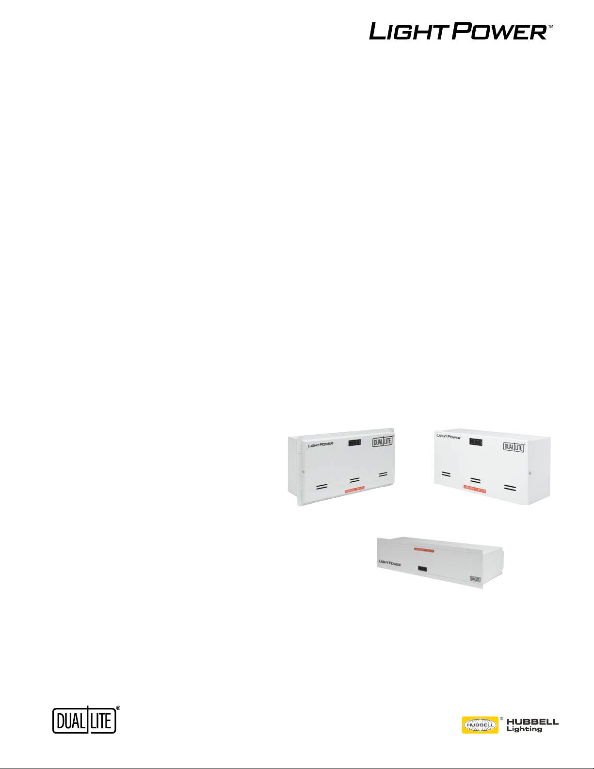
For LPS Series Micro Inverter Power Systems
Lead Calcium Battery Models: LPS32 and LPS55
Nickel Cadmium Battery Models: LPS20 and LPS35
Surface (-S), Recessed (-R) and Ceiling T-Grid (-T) Mounted Versions
1

2
READ AND FOLLOW ALL SAFETY INSTRUCTIONS
READ AND FOLLOW ALL SAFETY INSTRUCTIONS
IMPORTANT SAFEGUARDS
When using electrical equipment, basic safety precautions should always be followed,
including the following:
READ AND FOLLOW ALL SAFETY INSTRUCTIONS:
• Do not use outdoors.
• Do not let power supply cords touch hot surfaces.
• Do not mount near gas or electric heaters.
• Use caution when servicing batteries. Battery acid can cause burns to skin and eyes. If
-
ately.
• Equipment should be mounted securely in locations and at heights where it will not be read-
ily subjected to tampering by unauthorized personnel.
IMPORTANT SAFEGUARDS
When using electrical equipment, basic safety precautions should always be followed,
including the following:
READ AND FOLLOW ALL SAFETY INSTRUCTIONS:
• Do not use outdoors.
• Do not let power supply cords touch hot surfaces.
• Do not mount near gas or electric heaters.
• Use caution when servicing batteries. Battery acid can cause burns to skin and eyes. If
acid is spilled on skin or in eyes, ush acid with fresh water and contact a
physician immediately.
• Equipment should be mounted securely in locations and at heights where it will not be
readily subjected to tampering by unauthorized personnel.
• The use of accessory equipment not recommended by the MANUFACTURER may cause an
unsafe condition.
• The AC voltage rating of this equipmen
equipment to any other voltage.
• Do not use this equipment for other than its intended purpose.
• Servicing of this equipment
SAVE THESE IMPORTANT SAFETY INSTRUCTIONS
The installation and use of this product must comply with all national, federal, state,
municipal, or local codes that apply.
Please read this manual thoroughly before operating the LPS Inverter System.
For technical assistance, contact Dual-Lite’s Technical Support Center at 1-800-848-6439.
Technicians are available during normal working hours (EST).
ot connect
3

Table of Contents
Description Page
Section 100
System Installation Instructions
101. ....................................................................................................... 5
102. Receiving, Moving and Storing Systems and Batteries ...................................... 6
102.1 Shipping Damage ................................................................................................ 6
102.2 Temporary Storage of Units and Batteries ........................................................... 6
103. Installation Requirements .................................................................................... 6
103.1 Operating Environment ........................................................................................ 6
103.2 High Altitude Operation ........................................................................................ 6
104. Cabinet Mounting ................................................................................................ 7
104.1 Tools Required ..................................................................................................... 7
104.2 Mounting Hardware .............................................................................................. 7
104.3 Knockout Locations .............................................................................................. 7
104.4 Cabinet Mounting - Surface (-S) Models .............................................................. 7
104.5 Cabinet Mounting - Recessed (-R) Models .......................................................... 8
104.6 Cabinet Mounting - Ceiling T-Grid (-T) Models) ................................................... 8
105. AC Connections .................................................................................................. 9
105.1 AC Wiring Preparations ....................................................................................... 9
105.2 AC Input Voltage Selector Plug Installation ....................................................... 10
105.3 AC Input/output Wiring Connections to Terminal Block ..................................... 10
106. Battery Information ............................................................................................. 11
106.1 Tools ................................................................................................................... 11
106.2 Battery installation and Connection ................................................................... 11
106.3 Battery Voltage Check ........................................................................................12
107. Final Installation Checklist ..................................................................................12
108. System Start-Up Procedure ................................................................................12
109. System Test ........................................................................................................12
Section 200
Maintenance
200.1 Safe Shut Down Procedure ............................................................................... 13
200.2 Routine System Maintenance ............................................................................ 13
200.3 Manual Routine Inverter Tests ........................................................................... 13
200.4 Routine Battery Inspection and Maintenance .................................................... 14
200.5 Battery Replacement Procedure........................................................................ 14
200.6 Battery Disposal................................................................................................. 14
4
Section 100 System Installation Instructions
• Operating temperature: 20ºC to 30ºC (68ºF to 86ºF)
Section 100 System Installation Instructions
Input
• Input voltage: Universal 120 or 277Vac.
• Input frequency: 60HZ ±2%
• Input surge protection: Meets UL 924
Output
• Output voltage: Universal 120 or 277Vac, 60HZ. Other voltages available upon request
• Output regulation: (static) ±5% based on a 0% - 100% resistive load
• Minimum loading: none required
• Output distortion: Less than 3% THD linear load
• Load power factor: .44 lead to .44 lag
• Output frequency: ±0.3 Hz during emergency
• Time to transfer to inverter after a utility power failure: <1 second
Battery
• Battery type: Maintenance free sealed Lead Calcium or Nickel Cadmium
• Battery charger: Fully automatic dual-mode with temperature compensation
• Recharge time: Meets UL requirements (96 Hours)
• Battery protection: Automatic low-battery voltage disconnect and reverse polarity protection.
• Standard batteries: Sealed Lead-Calcium: 7-year life, Sealed Nickel Cadmium: 15-year life
• Battery voltage: 12Vdc (all models)
• Runtimes: 90 minutes standard.
• Operating temperature: 20ºC to 30ºC (68ºF to 86ºF)
• Relative humidity: 95% non-condensing
Input
• Input voltage: Universal 120 or 277Vac.
• Input frequency: 60HZ ±2%
• Input surge protection: Meets UL 924
Output
• Output voltage: Universal 120 or 277Vac, 60HZ. Other voltages available upon request
• Output regulation: (static) ±5% based on a 0% - 100% resistive load
• Minimum loading: none required
• Output distortion: Less than 3% THD linear load
• Load power factor: .44 lead to .44 lag
• Output frequency: ±0.3 Hz during emergency
• Time to transfer to inverter after a utility power failure: <1 second
Battery
• Battery type: Maintenance free sealed Lead Calcium or Nickel Cadmium
• Battery charger: Fully automatic dual-mode with temperature compensation
• Recharge time: Meets UL requirements (96 Hours)
• Battery protection: Automatic low-battery voltage disconnect and reverse polarity protection.
• Standard batteries: Sealed Lead-Calcium: 7-year life, Sealed Nickel Cadmium: 15-year life
• Battery voltage: 12Vdc (all models)
• Runtimes: 90 minutes standard.
Note: Lead Calcium battery performance rated at 25°C (77°F) for load, Nickel Cadmium battery performance
rated at 20°C to 30°C (68°F to 86°F) for load
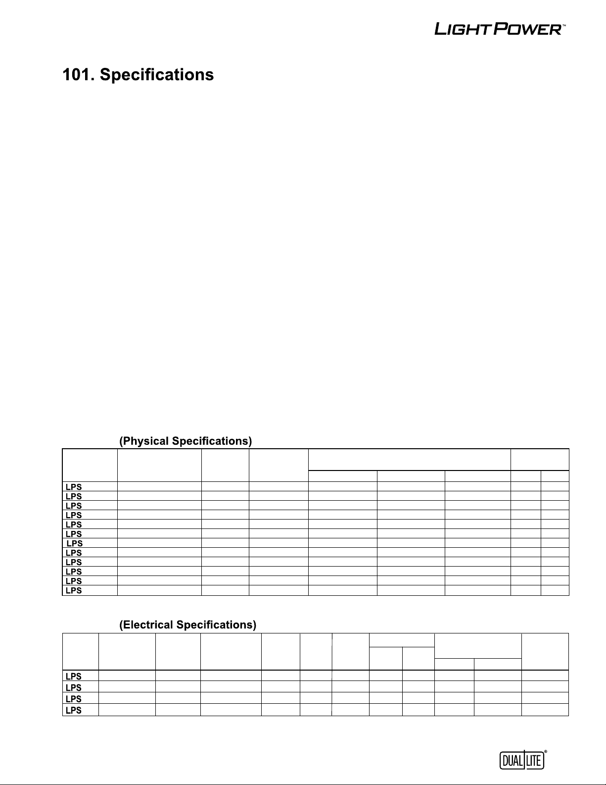
Table 1
System Housing Number System
Model Mounting Housing Of Installed Housing Dimensions Weight
Number Style Size Batteries Length Height Depth (Lbs.) (Kg.)
32-S Surface Small 1 143/4” (37.5cm)
55-S Surface Large 1 143/4” (37.5cm)
20-S Surface Small 1 143/4” (37.5cm)
35-S Surface Large 1 143/4” (37.5cm)
32-R Recessed Small 1 161/4” (41.3cm)
55-R Recessed Large 1 161/4” (41.3cm)
20-R Recessed Small 1 161/4” (41.3cm)
35-R Recessed Large 1 161/4” (41.3cm)
32-T Ceiling Recessed -- 1 237/8” (60.6cm) 61/4” (15.8cm) 8.0” (20.3cm) 15 6.8
55-T Ceiling Recessed -- 1 237/8” (60.6cm) 61/4” (15.8cm) 8.0” (20.3cm) 19 8.6
20-T Ceiling Recessed -- 1 237/8” (60.6cm) 61/4” (15.8cm) 8.0” (20.3cm) 12 5.4
35-T Ceiling Recessed -- 1 237/8” (60.6cm) 61/4” (15.8cm) 8.0” (20.3cm) 13 5.9
* System weights shown include installed batteries
3
/8” (18.7cm)
7
3
/8” (18.7cm)
7
3
/8” (18.7cm)
7
3
/8” (18.7cm)
7
7
/8” (22.5cm)
8
7
/8” (22.5cm)
8
7
/8” (22.5cm)
8
7
/8” (22.5cm)
8
1
3
/8” (7.9cm) 14 6.4
3
4
/8” (11.1cm) 18 8.2
1
3
/8” (7.9cm) 11 5.0
3
4
/8” (11.1cm) 12 5.4
1
3
/8” (7.9cm) 15 6.8
3
4
/8” (11.1cm) 19 8.6
1
3
/8” (7.9cm) 12 5.4
3
4
/8” (11.1cm) 13 5.9
*
Table 2
System Input/Output Capacity Power Battery DC Input Input Current Thermal Output Temp.
Model Voltage (90 Min) Battery Consum. Voltage Current 120Vac 277Vac In BTUs Range
Number (60Hz.) Watts/VA Type (Max.) (Vdc) (Adc) (Max.) (Max.) Standby Emergency (ºC)
32
55
20
35
120/277 32/32 Lead-Calcium 9W 12 3.4 0.34A 0.15A 7 32 20 to 30
120/277 55/55 Lead-Calcium 9W 12 5.7 0.54A 0.23A 7 47 20 to 30
120/277 20/20 Nickel Cadmium 9W 12 2.1 0.25A 0.11A 31 22 20 to 30
120/277 35/35 Nickel Cadmium 9W 12 3.8 0.37A 0.16A 31 35 20 to 30
5
 Loading...