

Page 1
UCL-SG3
: Jet-Phillips SHO/RHO, Guardian MC-1411.
NOTE: Quality and product improvement is our continuous aim
TAP
COM
INSTALLATION INSTRUCTIONS
HUBBELL StarGate SERIES
Important safety instructions pertaining to risk of fire, electric shock,
and injury to persons and/or property. READ AND SAVE THESE
INSTRUCTIONS.
Warnings:
Read and follow all instructions, electrical data markers, and wiring
labels before installation.
Installation and maintenance must be performed by a licensed
electrician only.
Install, operate, and maintain to meet all applicable codes.
The installer is responsible for safe and secure mounting, suitable for
the application.
To reduce fire and shock hazards, disconnect power before installation
or servicing.
Use protective equipment to avoid injury when installing and servicing
this product.
Provide proper grounding for all system components and use
appropriate wire connectors.
Failure to properly install this product will void manufacturer’s
warranty.
Use UCL-SGX-XXXXXX with the following products,
minimum size 21-1/8” square, 7-1/2” deep:
UCL-SG1
UCL-SG2
Houstonian (old style).
: Whiteway TD/RA-II.VN, Cooper CLS.
: LSI MA/DA, Whiteway RA, Jet-Phillips
Existing
Housing
General Information:
These instructions are not intended to be a comprehensive guide to all
installation issues. For technical assistance and/or warranty support,
contact the manufacturer at the phone number listed below.
Refer to existing ballast for electrical data, and to the retro-fit kit
labeling for replacement lamp specifications.
Ensure that the existing housing does not leak from above and is
secured properly to the canopy and can safely support the additional
weight of this retro-fit kit.
Installation:
1.
Remove lens frame assembly from existing luminaire housing and
discard.
2.
Remove lamp, reflector, ballast cover, and any other components that
may interfere with the installation of this kit. It is not necessary to
remove all components (socket, capacitor, etc.) unless it is determined
that they will prevent successful installation.
3. Disconnect all ballast leads.
4.
Remove all hardware from door flange and any caulking from corners
that may interfere with hinge operation.
5.
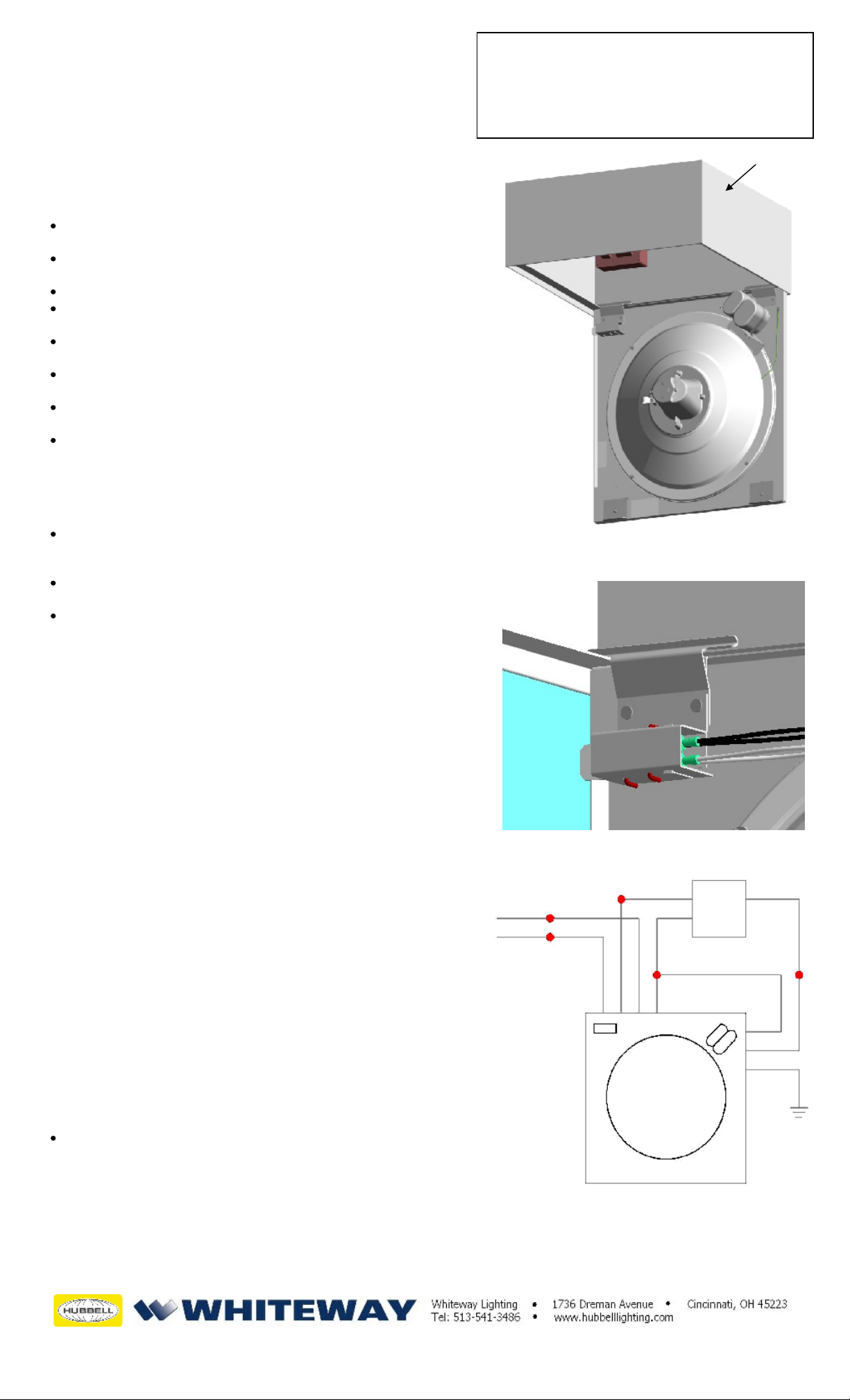
Hang the retro-fit panel on a side of the housing that is adjacent to
the existing ballast. Orient and hang the panel on the housing
flange as shown in Figures 1 and 2.
6.
Make wiring connections in accordance with applicable codes and
the wiring diagram at right. Supply voltage must match the desired
ballast input lead.
7.
Hinge panel up, while pushing towards the hinges, until the panel
is nearly closed against the housing flange. Care must be taken to
avoid pinching wires while closing.
8.
Slide both latch locking screws toward the hinges and close the
panel fully against the housing flange.
9. Slide the latches
fully forward and
securely
tighten screws.
Figure 2
WHT
BLK
INPUT
COM
Figure 1
CAP
BLST
COM
CAP
GRN
Available Accessories:
UCL-SG-HS - House-side shield/reflector: Order one set for
180° shielding or two sets for 360° shielding.
Patent 6,182,848 Other patents pending.
UCL-SGX-XXXXXX
PANEL
.
Data in this bulletin is subject to change without notice.
268-1286-9901
 Loading...