

Page 1
INSTALLATION INSTRUCTIONS FOR
SLS REMOTE BALLAST SYSTEM
Catalog Logic: R E M - XXXXH X-X-X X
Fixture Watts:
1000 1500 1650
Fixture Voltage:
(2) 208v (3) 240v (E) 220v/50hz
(4) 277v (5) 480v (6) 347v
Ballast Quantity:
2 through 6
A complete system includes the ballast enclosure, lighting fixtures, wiring harness, crossarms and poles.
Warning!
• Dangerous voltages exist within this product.
• To reduce fire and shock hazards disconnect power before servicing.
• To reduce the risk of injury, operate and maintain to meet
all applicable codes.
• Installation is to be performed by a qualified electrician
only.
• Provide proper ground for all system components.
This ballast enclosure should be installed at a minimum
ÞÞ
Þ
ÞÞ
height of 10 feet (3 meters) above grade.
Catalog Logic: R E M - X X X X H X - X - X X
Optional Features:
(SH) Solution Harness Ready
(TB) **Thermal Magnetic Breaker
**Standard for 240v and below
(WP) Wood or other Solid Pole
(T) Wire Three Phase
• Read and follow all instructions and labels before and during installation.
• Failure to properly install this product will void
manufacturer's warranty .
• Handle and secure so ballast enclosure cannot fall.
• Use protective equipment to avoid injury during installation of this heavy product.
• Do not route wiring through top of enclosure.
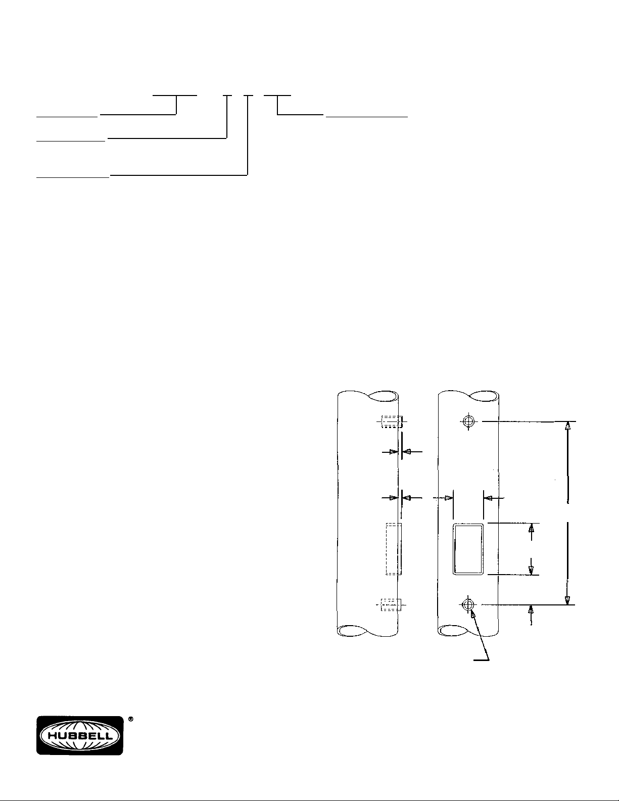
Enclosure Installation - Steel and Concrete Poles
(Figures 1, 2, & 3) (See Enclosure Installation - Wood Poles)
Important: Installation requires the use of a pole equipped
with mounting couplings and wireway . (Figure 1)
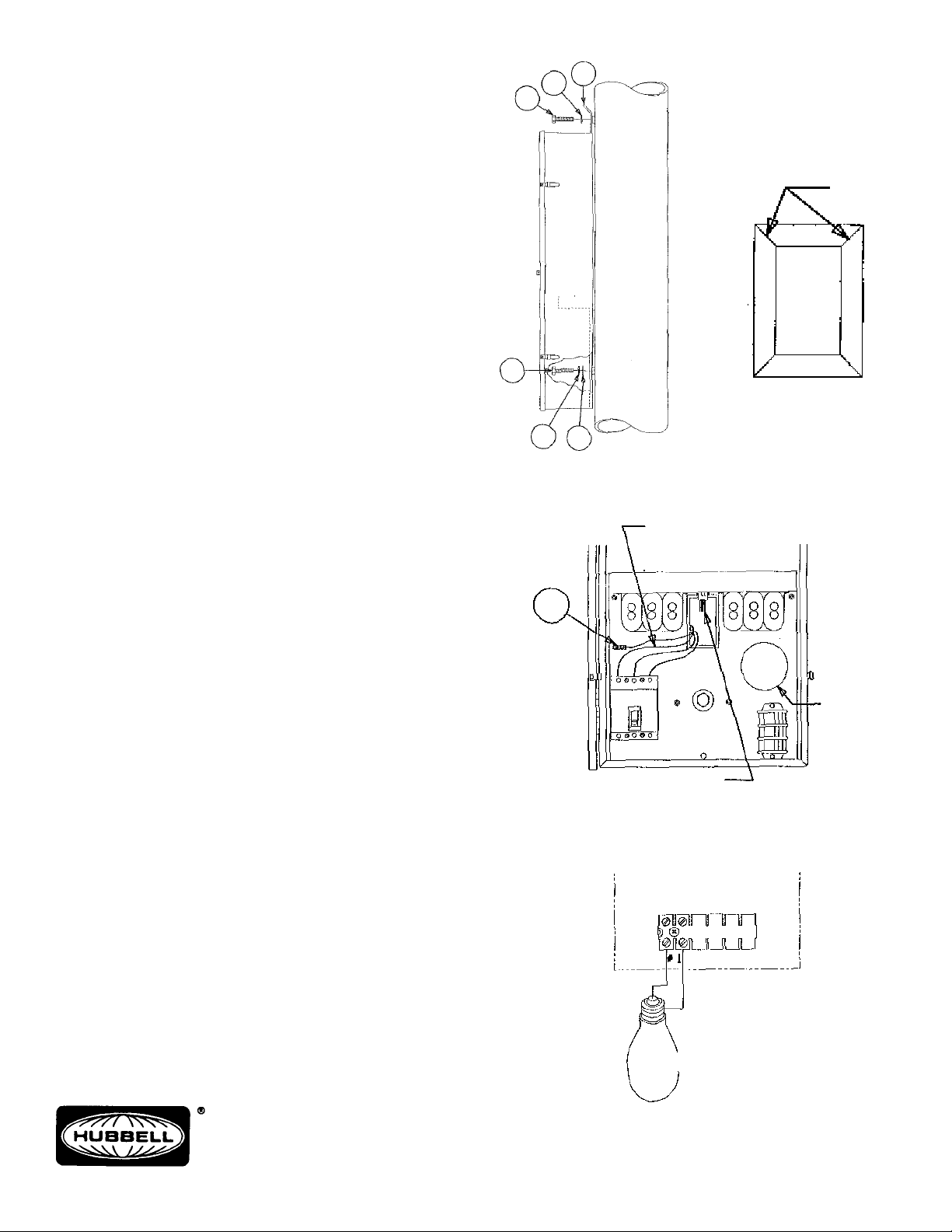
1. Remove peel strip from gasket supplied in hardware bag.
2. Apply gasket to the back of enclosure around the 2-1/2"
x 4-1/2" (63.5mm x 1 14.3mm) hole. (Figure 3)
Important: Clean the surface around the opening in the
back of enclosure to remove oil and dirt before applying
the gasket.
3. Install bolt (2) and lockwasher (3) in the top coupling.
(Figure 2) Leave 1" (25.4mm) of thread exposed.
4. Position lift bracket (4) over the bolt (2) and lockwasher
(3).
NOTE: The top of keyhole in bracket must contact the
bolt to support the 280 pound (127Kg) enclosure.
5. Align the wireway opening in the enclosure with the wireway opening in the pole. Do not damage gasket!
6. Install bolt, lockwasher and flatwasher through hole inside of enclosure and into the coupling in pole.
7. Tighten both bolts to a minimum of 40ft/lbs.
8. Seal all openings between pole and enclosure.
3/8"
TYP.
3/8"
COUPLING W/ 3/4 - 10
INTERNAL THREADS
FOR 3/4" BOL T
3"
41"
5"
4 - 7/8"
Hubbell Lighting, Inc.
A Subsidiary of Hubbell Incorporated
2000 Electric Way
Christiansburg, VA 24073-2500
(540) 382-6111
FAX (540) 382-1526
FIGURE 1
268-1157-9901
Page 2
Enclosure Mounting - Wood Pole -WP) Figures 2, 3
1. Install one 3/4" (19mm) diameter bolt (2) (by others) and
lockwasher (3) in pole at location for top enclosure support. (Figure 2) Leave 1" (25.4mm) of thread exposed.
2. Position the lift bracket (4) over bolt (2) and lockwasher
(3).
NOTE: The top of keyhole in bracket must contact the
bolt to support the 280 pound (127Kg) enclosure.
3. Install bolt, lockwasher and flatwasher through hole inside of enclosure and into the wood pole.
4. Tighten both bolts securely to a minimum of 40ft/lbs.
5. Seal all openings between pole and enclosure.
6. Drill wire way hole of desired size from inside of enclosure at center of hole “A” in electrical panel. (Figure 4)
NOTE: This wireway hole may be drilled in the bottom of
enclosure. Do not damage wires or components!
7. Attach conduit to enclosure with watertight fittings.
Wiring and Electrical Instructions
3 The enclosure voltage must match the supply voltage.
3 Standard wiring is single phase. Three phase requires
a “-T” on the catalog number. (Consult factory)
3 Total operating amperage is shown on the inside of door .
3 Enclosures are factory wired to operate as a separate
unit.
(Contact factory for wiring multiple enclosures in series)
3 Enclosure includes factory fusing of all branch circuits.
3 Enclosure includes internal electrical switching:
• Thermal Magnetic Breaker is standard for 208v, 220v
and 240v
• Load Break Switch is standard for 277v, 347v and 480v
• “-TB” indicates Thermal Magnetic Breaker for 277, 347v
and 480v .
2
2
3
3
FIGURE 2
7
4
CLOSE
GAPS
FIGURE 3
5
CUSTOMER
SUPPLY
LEADS
Supply Wiring:
1. Connect the supply wires to the proper lugs on switch.
2. Connect ground wire (6) to the ground lug (7).
3. Provide effective strain relief to prevent wire damage.
4. Comply with all national and local electrical codes.
Caution: Protect exposed wires with approved insulators.
Fixture Wiring into Enclosure:
1. Connect the socket wires to the socket terminal block
inside enclosure. (Figure 5) or
If catalog number includes “-SH”, connect the male plug
of wiring harness and the female harness plug. (Figure
4) Snap securely .
2. Enclosure shall be properly grounded.
3. Close door and engage the latches. A lock is optional.
These instructions are not intended to be a comprehensive
guide to all Installation issues.
The installer is responsible for safe, secure mounting suitable for the application.
Once the enclosure is installed, give these instructions to
the equipment owner.
Hubbell Lighting, Inc.
A Subsidiary of Hubbell Incorporated
2000 Electric Way
Christiansburg, VA 24073-2500
(540) 382-6111
FAX (540) 382-1526
HOLE
“A”
“-SH” HARNESS
PLUG
FIGURE 4
REMOTE ENCLOSURE
SOCKET TERMINAL BLOCK
FIXTURE #1
FIGURE 5
268-1157-9901
Page 3

SYSTÈME BALLAST SÉPARÉ SLS
DIRECTIVES DE MONTAGE
Logique Du Catalogue - R E M - XXXXH X-X-X X
Catalog Logic: R E M - XXXXH X-X-
XX
Puissance - Watts
1000 1500 1650
Tension
(2) 208v (3) 240v (E) 220v/50hz
(4) 277v (5) 480v (6) 347v
Nombre de ballasts
Optional Features:
(SH) Solution Harness Ready
(TB) **Thermal Magnetic Breaker
**Standard for 240v and below
(WP) Wood or other Solid Pole
(T) Wire Three Phase
2 à 6
Le système complet comprend le boîtier du ballast, les luminaires, les câbles, les consoles et les poteaux.
AVERTISSEMENT!
• Ce dispositif contient des tensions dangereuse.
• Débrancher le circuit avant de procéder à la maintenance afin de
réduire tout risque d’incendie ou de choc électrique.
• Afin de réduire tout risque de blessure, effectuer le montage,
l’exploitation et la maintenance en conformité avec tous les codes
applicables.
• Doit être installé par un électricien qualifié.
• S’assurer de la mise à la terre adéquate de tous les composants.
Il est recommandé d’installer ce boîtier de ballast séparé à une
ÞÞ
Þ
ÞÞ
hauteur minimum de 3 m au-dessus du sol.
MONT AGE DU BOÎTIER SUR POTEAUX EN ACIER ET EN BÉTON
- (figures 1, 2 et 3)
(Figures 1,2 et 3). (Voir montage pour poteaux en bois).
IMPORT ANT - L’installation requiert l’utilisation d’un poteau équipé
de manchons de fixation et d’orifices de câblage tel qu’illustré dans
la figure 1.
• Avant le montage, lire attentivement et suivre toutes les directives et les étiquettes.
• Le montage inapproprié de ce produit annule la garantie du
fabricant.
• Manipuler et fixer de façon à s’assurer que le boîtier du ballast ne
pourra pas tomber.
• Utiliser l’équipement de protection pour éviter les blessures pendant le montage de ce produit très lourd.
• Ne pas acheminer les câbles par le dessus du boîtier
1.Enlever la pellicule de la garniture de joint incluse dans le sac de
visserie.
2.Appliquer la garniture de joint sur l’arrière du boîtier autour de
l’ouverture de 63,5 mm x 114,3 mm (figure 3).
3.Visser un boulon (2) avec une rondelle de blocage (3) dans le
manchon supérieur (figure 2) en laissant environ 25 mm de filet à
découvert.
4.Placer le crochet de retenue (4) sur le boulon (2) et la rondelle de
blocage (3).
REMARQUE- Le haut de l’ouverture du crochet doit reposer sur
le boulon pour supporter les 127 kg du boîtier.
5. Aligner l’ouverture de câblage du boîtier avec l’ouverture de
câblage du poteau. Ne pas endommager la garniture de joint.
6.Insérer le boulon avec la rondelle de blocage et la rondelle plate
dans l’ouverture à l’intérieur du boîtier et dans le manchon du
poteau.
7.Serrer les deux boulons à un couple d’au moins 55 N·m.
8.Sceller toutes les ouvertures entre le poteau et le boîtier.
MONTAGE DU BOÎTIER SUR POTEAU EN BOIS (-WP).
Figures 2 et 3
1.Placer un boulon de 19 mm de diamètre (2) (non fourni) dans
une rondelle de blocage (3) à travers le poteau de bois à
l’emplacement désiré pour le support supérieur du boîtier (Figure
2) en laissant environ 25 mm de filet à découvert.
Hubbell Lighting, Inc.
A Subsidiary of Hubbell Incorporated
2000 Electric Way
Christiansburg, VA 24073-2500
(540) 382-6111
FAX (540) 382-1526
3/8"
TYP.
3/8"
MANCHON À FILETAGE
INTÉRIEUR 3/4 - 10 POUR
BOULON DE 19 MM DE
DIAMÉTRE
FIGURE 1
3"
41"
5"
4 - 7/8"
268-1157-9901
Page 4

2.Placer le crochet de retenue (4) sur le boulon (2) et la rondelle de
blocage (3).
REMARQUE- Le haut de l’ouverture du crochet doit reposer sur
le boulon pour supporter les 127 kg du boîtier.
3.Insérer le boulon avec la rondelle de blocage et la rondelle plate
dans l’ouverture à l’intérieur du boîtier et dans le poteau de bois.
4.Serrer les deux boulons à un couple d’au moins 55 N·m.
5.Sceller toutes les ouvertures entre le poteau et le boîtier.
6.De l’intérieur du boîtier, forer une ouverture de diamètre
convenable pour le câblage au centre de l’ouverture «A» dans le
panneau d’électricité (figure 4).
REMARQUE - L’ouverture pour le câblage peut être percée au
bas du boîtier. S’assurer de prendre toutes les précautions
nécessaires pour ne pas endommager le câblage et les
composants.
7.Raccorder le conduit au boîtier au moyen de raccords étanches à
l’eau.
CÂBLAGE et RENSEIGNEMENTS ÉLECTRIQUES:
3 La tension assignée du boîtier doit correspondre à la tension
d’alimentation.
3 Le câblage standard est monophasé. Un système triphasé requiert
un «-T» dans le numéro de référence (Consulter l’usine).
3 Le courant total est indiqué à l’intérieur de la porte.
3 Le boîtier est câblé en usine pour fonctionner en tant qu’unité
séparée. (Consulter l’usine pour le câblage de plusieurs boîtiers
en série).
3 Les boîtiers incluent les fusibles montés en usine pour chaque
circuit de dérivation.
3 Les boîtiers contiennent des dispositifs de commutation internes:
• Disjoncteur thermo-magnétique standard pour 208 V, 220 V et
240 V.
• Interrupteur sous charge standard pour 277 V, 347 V et 480 V .
• «-TB» indique un disjoncteur thermo-magnétique pour 277 V,
347 V et 480 V.
CÂBLAGE D’ALIMENT ATION
1.Raccorder les câbles d’alimentation aux bornes appropriées de
l’interrupteur.
2.Raccorder le file de MALT (6) à la borne de MALT (7).
3.Prévoir un détendeur pour éviter les dommages aux câbles
4. Respecter les consignes des codes nationaux et locaux de
l’électricité.
ATTENTION - Couvrir les conducteurs exposés au moyen
d’isolants homologués.
2
2
3
3
FIGURE 2
7
4
CLOSE
GAPS
FIGURE 3
5
FILS D'ALIMENTATION
DU CLIENT
OUVERTURE
«A»
CÂBLAGE DU LUMINAIRE DANS LE BO¸ITIER
1.Raccorder les fils de la douille à la plaque à bornes de la douille à
l’intérieur du boîtier (Figure 5) ou :
Si le numéro de référence contient «-SH», raccorder la fiche mâle
à la fiche femelle du faisceau de câbles (Figure 4). Les enclencher
fermement.
2.Le boîtier doit être mis à la terre adéquatement.
3.Fermer la porter et enclencher les loquets. Une serrure est facultative.
Ces directives ne constituent pas un guide exhaustif répondant à
tous les problèmes de montage.
L’installateur est responsable de la sécurité du montage pour cette
application.
Lorsque le boîtier est installé, remettre les directives au propriétaire
du matériel.
Hubbell Lighting, Inc.
A Subsidiary of Hubbell Incorporated
2000 Electric Way
Christiansburg, VA 24073-2500
(540) 382-6111
FAX (540) 382-1526
FICHE DU FAISCEAU
DE CÂBLES «-SH»
FIGURE 4
BOÎTIER SÉPARÉ
PLAQUE À BORNES
DE LA DOUILLE
LUMINAIRE N° 1
FIGURE 5
268-1157-9901
Page 5

SISTEMA DE REACTANCIA SEPARADA SLS
INSTRUCCIONES DE INSTALACIÓN
Referencia De Catálogo - R E M - XXXXH X- X-X X
Vatios des
artefacto
Tensión del artefacto
(2) 208v (3) 240v (E) 220v/50hz
(4) 277v (5) 480v (6) 347v
Candidad de reactancias
Catalog Logic: R E M - XXXXH X-X-X
Caracteristicas opcionales:
(SH) Mazo de conductores preparado
(TB) **Disyuntor magnético térmico
**Regular para V~240 y menos
(WP) Poste sólido de madera u otro material
(T) Cable trifásico
2 à 6
El sistema completo consta de una caja de reactancia, artefactos de alumbrado, un mazo de conductores, traviesas y
postes.
¡ADVERTENCIA!
• Dentro de este producto existen tensiones peligrosas.
• Desconectar la energía eléctrica antes de cualquier operación
de mantenimiento para reducir los riesgos de incendio y de
choque eléctrico.
• Para reducir el riesgo de lesiones, hay que hacer funcionar y
mantener el sistema de conformidad con todos los códigos
aplicables.
• La instalación sólo debe ser realizada por un electricista
competente.
• Asegurar la puesta a tierra apropiada para todos los
componentes del sistema.
• Antes de la instalación y mientras se realiza, se deben leer y
seguir todas las instrucciones e indicaciones en las etiquetas.
• Si este producto no se instala correctamente, dejará de tener
validez la garantía del fabricante.
• La reactancia debe manipularse y colocarse firmemente para
evitar que se caiga.
• Usar equipo protector para evitar lesiones durante la instalación
de este producto pesado.
• No pasar cables por la parte superior de la caja.
Esta caja de reactancia debería instalarse a una altura mínima
ÞÞ
Þ
ÞÞ
de 3 metros sobre el nivel del suelo.
INSTALACIÓN DE LA CAJA: POSTES DE ACERO Y DE HORMIGÓN
(Figuras 1,2 y 3) (Ver Montaje de la caja: postes de madera)
Importante: La instalación requiere un poste equipado con
manguitos de fijación y que tenga una abertura de cableado (Figura 1).
1. Retirar la cinta adhesiva del burlete provisto en la bolsa de
accesorios.
2.Adherir el burlete al dorso de la caja, alrededor del hueco de 63,5
mm x 114,3 mm (Figura 3).
3. Insertar el perno (2) con la arandela de seguridad (3) en el
manguito superior (Figura 2). Dejar visibles 25 mm de rosca.
4.Colocar la pestaña colgadera (4) sobre el perno (2) y la arandela
de seguridad (3).
NOTA: La parte superior del orificio en la pestaña colgadera debe
quedar apoyada en el perno para sostener una caja de 127 kg.
5.Alinear la entrada de cables de la caja con la abertura de cableado
del poste. ¡No dañar el burlete!
6.Insertar el perno, la arandela de seguridad y la arandela plana a
través del orificio dentro de la caja y en el manguito del poste.
7.Ajustar los dos pernos con un par mínimo de 55 N m.
8.Sellar todas las aberturas entre el poste y la caja.
MONTAJE DE LA CAJA: POSTES DE MADERA (-WP) (Figuras 2,3)
1.Insertar un perno (2) de 19 mm de diámetro (provisto por otros)
con una arandela de seguridad (3) en el poste, en el lugar deseado
para sostener la parte superior de la caja (Figura 2). Dejar visibles
25 mm de rosca.
Hubbell Lighting, Inc.
A Subsidiary of Hubbell Incorporated
2000 Electric Way
Christiansburg, VA 24073-2500
(540) 382-6111
FAX (540) 382-1526
3/8"
TYP.
3/8"
MANGUITOS CON ROSCAS
INTERIORES 3/4-10 PARA
PERNOS DE 19 MM
FIGURA 1
3"
41"
5"
4 - 7/8"
268-1157-9901
Page 6

2.Colocar la pestaña colgadera (4) sobre el perno (2) y la arandela
de seguridad (3).
NOTA: La parte superior del orificio de la pestaña colgadera debe
quedar apoyada en el perno para sostener la caja de 127 kg.
3.Insertar el perno, la arandela de seguridad y la arandela plana a
través del orificio dentro de la caja y en el poste de madera.
4.Ajustar los dos pernos con un par mínimo de 55 N m.
5.Sellar todas las aberturas entre el poste y la caja.
6.Perforar una abertura para cableado del diámetro que se desee
desde el interior de la caja en el centro del orificio “A” de la caja
eléctrica (Figura 4).
NOTA - Esta abertura para cableado puede perforarse por encima
de la caja. ¡No dañar los cables ni los componentes!
7.Unir el conducto a la caja con accesorios impermeables.
INSTRUCCIONES ELÉCTRICAS Y CABLEADO
3 La tensión de la caja debe coincidir con la tensión de alimentación.
3 El cableado ordinario es monofásico. El trifásico requiere la
indicación «-T» en el número de catálogo (Consultar a la fábrica).
3 Dentro de la tapa se indica el amperaje de servicio total.
3 Las cajas están cableadas en fábrica para funcionar como
unidades separadas (Comunicarse con la fábrica si se quiere
cablear múltiples cajas en serie).
3 La caja comprende fusibles instalados en fábrica para todos los
circuitos derivados.
• La caja comprende interruptores eléctricos internos:
• Un disyuntor termo magnético regular para V~208, V~220 y
V~240
• Un interruptor de carga regular para V~277, V~347 y V~480
• «-TB» indica disyuntor termo magnético para V~277, V~347 y
V~480
2
2
3
4
3
5
FIGURA 2
CERRAR EL
BURLETE
FIGURA 3
CABLES DE ALIMENT ACIÓN
PROVISTOS POR EL CLIENTE
CABLEADO DE ALIMENT ACIÓN
1.Conectar los cables de alimentación con los bornes
correspondientes del interruptor.
2.Conectar el cable de tierra (6) con el borne de puesta a tierra (7).
3.Aplicar un alivio de tensión apropiado para evitar daños en los
cables.
4.Cumplir con todos los códigos eléctricos nacionales y locales.
PRECAUCIÓN - Proteger los cables descubiertos con aislantes
aprobados.
CABLEADO DEL ARTEFACT O EN LA CAJA
1.Conectar los cables del portalámparas con el bloque de bornes
del portalámparas dentro de la caja (Figura 5), o
Si el número de catálogo incluye la indicación «-SH», conectar la
clavija macho y la clavija hembra del mazo de conductores (Figura
4). Enganchar firmemente.
2.La caja deberá estar correctamente conectada a tierra.
3.Cerrar la tapa y enganchar las trabas. Puede usarse un candado,
como opción.
Estas instrucciones no están concebidas como una guía exhaustiva
sobre todos los aspectos de la instalación.
El instalador es responsable de que el montaje resulte seguro, quede
firme y sea apropiado para la aplicación.
Una vez instalada la caja, entregar estas instrucciones al propietario
del equipo.
7
ORIFICIO
«A»
CLAVIJA «-SH» DEL
MAZO DE CONDUCTORES
FIGURA 4
CAJA SEPARADA
BLOQUE DE BORNES DEL
PORTALÀMPARAS
ARTEFACTO N° N
Hubbell Lighting, Inc.
A Subsidiary of Hubbell Incorporated
2000 Electric Way
Christiansburg, VA 24073-2500
(540) 382-6111
FAX (540) 382-1526
FIGURA 5
268-1157-9901
 Loading...