

Page 1
PLD9M-2H
ALBALBEC-16121200912/20/161
4 3
2 1
D
C
B
REV DATE RECORD DESN CHCK
Emergency LED Battery Pack Installation,
Operation, and Service Instructions
CLASS 2 OUTPUTP/N:93071774
IMPORTANT SAFEGUARDS
When using electrical equipment, basic safety precautions should
always be followed including the following.
READ AND FOLLOW ALL SAFETY
INSTRUCTIONS
1. Do not join converter connection until installation is complete and AC power is supplied to the emergency driver.
2. This product is for use with an emergency LED lighting load and supplies 9.0 W of constant output power to
LED lamps rated from 20-56 Vdc. Operates emergency LED load in the emergency mode for a minimum
of 120 minutes.
3. Make sure all connections are in accordance with the NEC and any local regulations.
4. To reduce the risk of electric shock, disconnect both normal and emergency power supplies and converter
connector from the emergency driver before servicing.
5. This emergency driver is suitable for factory or eld installation.
6. Do not use outdoors. This product is suitable for use in damp locations where the ambient temperature is 0°C
minimum, +55°C maximum. Product is not suitable for heated air outlets and wet or hazardous locations.
7. An unswitched AC power source is required (120-277 VAC, 50/60 Hz).
8. Do not install near gas or electric heaters.
9. Do not attempt to service the battery. A sealed, no-maintenance battery is used that is not eld replaceable.
Contact Dual-Lite for information on service.
10. The use of accessory equipment not recommended by the manufacturer may cause an unsafe condition.
11. Do not use this product for other than intended use.
12. Servicing should be performed by qualied service personnel.
13. Equipment should be mounted in locations and at heights where it will not be subjected to tampering by
unauthorized personnel
SAVE THESE INSTRUCTIONS
WARNING - This product contains chemicals known to the State of California to cause cancer,
birth defects, and/or other reproductive harm. Thoroughly wash hands after installing, cleaning,
This equipment has been tested and found to comply with the limits for a Class A digital device,
pursuant to part 15 of the FCC Rules. These limits are designed to provide reasonable protection
against harmful interference when the equipment is operated in a commercial environment.
and used in accordance with the instruction manual, may cause harmful interference to radio
interference in which case the user will be required to correct the interference at his own expense.
SEE UNIT LABEL FOR ADDITIONAL MODEL SPECIFICATIONS
SAVE THESE INSTRUCTIONS FOR USE BY OWNER/OCCUPANT
or otherwise touching this product.
This equipment generates, uses, and can radiate radio frequency energy and, if not installed
communications. Operation of this equipment in a residential area is likely to cause harmful
INSTALLER:
CAUTION: DISCONNECT POWER DURING INSTALLATION AND BEFORE SERVICING.
READ ALL INSTRUCTIONS COMPLETELY BEFORE STARTING INSTALLATION.
Page 2
INSTALLATION
LARGE
BUSHING
ALBALBEC-1612120095/22/171
2 1
D
C
B
REV DATE RECORD DESN CHCK
ILLUSTRATION 2
LED EM DRIVER
CAUTION: SUPPLY AC POWER TO THE EMERGENCY DRIVER BEFORE JOINING EITHER
CONVERTER CONNECTOR RED WIRES
This product is suitable for field installation with suitable LED loads including LED luminaires, DC voltage driven LED
replacements for fluorescent lamps and others. There are 4 checks to determine if your luminaire is eligible for use with this
LED battery pack.
1. Ensure the LED load's rated power is greater than or equal to the power output of this emergency LED driver (9W). This is to ensure that this emergency product will not
produce more power than the LED load can handle, thus ensuring that the LED load will not be damaged when the system is in the emergency mode.
2. Verify the forward voltage of the luminaire's LED array is within the limits of this emergency LED driver. The forward voltage of the LED array is commonly designated as Vf
and should be found on the luminaires markings, in the luminaire specications, or imprinted directly on the LED arrays. If multiple LED arrays are to be driven, verify that
the total forward voltage is within the limits of this product. Using a voltage meter, it may be possible to directly measure the voltage across the LED array when operating
from the AC driver.
3. Ensure the output current of the LED driver does not exceed 1.6 Amps. This is the current into the blue wire.
4. Ensure the LED xture’s rated efcacy is equal to or greater than 65 lm / watt. This is to ensure that the LED xture can be mounted at or below the maximum rated mounting
height of 28.4ft.
5. Ensure there will be sufcient light output in the end application. Estimate the emergency egress lighting illumination levels by doing the following:
a. Find the efcacy of the LED lighting xture, Luminaire efcacy information can be found at the Design Lights Consortium website (http://www.designlights.org), Energy
Star - Certied Products - product nder website (http://www.energystar.gov/productnder) or given by the luminaire manufacturer on product catalog specication
sheets. The LED xture efcacy will be given in lumens per watt (lm/w).
b. Lumens can be calculated by multiplying the output power of the emergency LED driver (9W) by the efcacy of the LED load.
In many cases the actual lumen output in emergency mode will be greater than this calculation gives, however it will provide a good estimate for beginning the lighting
design of the system.
Lumens In Emergency Mode = Lumens Per Watt of Fixture * Output Power of Chosen Product
(LUMENS) = (LM/W) * W
c. Using the results of this calculation and industry standard lighting design tools, calculate the anticipated illumination levels in the path of egress.
NOTE: This product has been designed to reliably interface with a wide selection of LED loads and is electrically
compatible with every simple LED array that meets criteria 1 - 4 above. However, compatibility cannot be
guaranteed with all current and future LED systems. Compatibility testing of the end-use system is suggested.
Please contact the factory with any questions.
NOTE: After installation, it will be necessary to measure the egress lighting illumination levels to ensure it
complies with national, state and local code requirements.
Installation of this Emergency LED Driver will vary based on the luminaire type, however, generally follow these steps.
Step 1. Disconnect AC power to the LED lighting xture. Remove lens and ballast channel cover from LED xture if applicable. (see illustrations 2 & 4)
Step 2. Using the 2 supplied screws, mount the LED emergency driver.
The lighting xture instructions might provide suggestions on the driver mounting location.
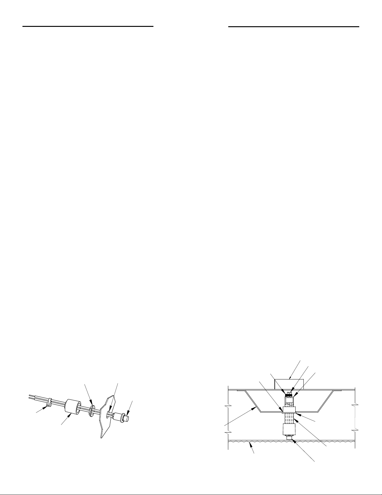
Step 3. Test switch/indicator light can be mounted directly to a xture surface thru a 1/2 inch diameter hole. Once nut is tightened, slip UL switch cover over wires,
pushing cover against xture surface completely covering switch, then afx ty-wrap over wires against cover to secure. Switch should be visible once xture is installed.
(see illustration 1 & 4)
Step 4. Test switch/indicator light can also be installed onto a driver channel cover through a 7/8 inch diameter hole (see illustrations 2 & 3.) Trim plastic tube to desired length,
afx UL switch cover as shown and place into tube. Afx both the small bushing and the large bushing onto the plastic tube as shown. Connect tie wrap onto wires,
tighten and insert into channel. Switch should be visible once xture is installed.
TY-WRAP
SUPPLIED NUT
93071446
UL SWITCH
COVER
1/2" DIA.
THRU HOLE
ILLUSTRATION 1
SUPPLIED TEST SWITCH/
INDICATOR LIGHT
BALLAST
CHANNEL
COVER
TIE WRAP
7/8" DIA THRU
HOLE
FIXTURE
DIFFUSER
LENS
SW LEADS
SMALL
BUSHING
LARGE
BUSHING
SW INDICATOR
PLASTIC
TUBE
93084715
Page 3

SW INDICATOR
LARGE
BUSHING
4 3
2 1
REV DATE RECORD DESN CHCK
RED
RED
WHT/RED
BLACK
VIOLET (+)
BROWN (-)
WHITE
WHT/BLK
BLUE
YEL/BLK
YELLOW
LED (+)
LED (-)
AC DRIVER (-)
AC DRIVER (+)
SW 1
WHITE
PLD10M
EM LED
DRIVER
LED LOAD
AC DRIVER
HOT
COMMON
VIOLET (+)
BROWN (-)
CONVERTER BATTERY CONN.
TEST SW/LED INDICATOR
AC DRIVER (-)
AC DRIVER (+)
LINE 1
LINE 2
HOT
SW 2
EMERGENCY BACK-UP, AC DRIVER
AND DIMMING
ALBALBEC-1601270034/28/161
2 1
D
C
REV DATE RECORD DESN CHCK
ALBALBEC-16121200912/20/161
4 3
2 1
D
C
B
A
REV DATE RECORD DESN CHCK
ILL-PLD10M UNIT MTG
ALB 05/22/17
This document contains confidential and proprietary information of Dual
Lite. Receipt or possession of this document does not convey any rights to
reproduce or disclose its contents, or to make, use , or sell anything it may
disclose. Reproduction, disclosure, or use of the document or its contents,
without the specific written authorization of Dual Lite, may violate the
intellectual property rights of Dual Lite.
DIMENSIONS IN INCHES
DIMENSIONS IN [ ] IN MM
CONFORMS TO ASME Y14.5M
DRAWN BY:
CHECKED BY:
CRITICAL DIMENSIONS
UNSPECIFIED TOLERANCES: INCHES
X.XX=
u
0.12
FRACTIONS=
u
1/32 ANGULAR TOLERANCE=u1
v
THIS ILL IS USED ON INSTRUCTION SHEET 93078192
MOUNT PLD10M UNIT
ON TOP OF LED
FIXTURE
SWITCH
INDICATOR
"CAUTION"
LABEL
"STATUS"
LABEL
LED MTG PLATE
(LENS NOT SHOWN)
TYPICAL LED
LIGHTING
FIXTURE
93084710
93084710
ILLUSTRATION 4
PLASTIC
TUBE
TY-WRAP
UL SWITCH
COVER
93071446
ILLUSTRATION 3
SMALL
BUSHING
Mounting Height: This product meets or exceeds the NFPA minimum light requirements
with all loads, down to the smallest rated lamp load, at heights up to 28.4ft (8.7m).
Many factors inuence emergency illumination levels, such as the lamp load selected,
luminare design, and environmental factors, therefore end use verication is necessary.
For installations where the attached luminaire is mounted at heights greater then 28.4ft
(8.7m), the level of illumination must be measured in the end application to ensure the
requirements of NFPA 101 and local codes are satised.
Step 5. Select correct wiring diagram to connect the emergency driver to the LED load, AC LED driver and Switch. Make sure all connections are in accordance with the National
Electrical Code and any local regulations.
Step 6. Install the labels “CAUTION” & “STATUS” in a visible location (see illustration 4).
Step 7. After installation is complete, supply AC power to the emergency ballast and join the invertor connector.
Step 8. At this point, power should be connected to both the AC driver and the emergency driver, and the charging indicator light should illuminate indicating the battery
is charging.
Step 9. A short-term discharge test may be conducted after the emergency ballast has been charged for one hour.
Step 10. Charge for 24 hours before conducting a long-term discharge test. Refer to “Operation” section below
WIRING
Note: Make sure the necessary branch circuit wiring is available. An unswitched source of power is required.
The emergency ballast must be fed from the same branch circuit as the AC ballast.
EMERGENCY DRIVER AND AC DRIVER MUST BE FED FROM THE SAME BRANCH CIRCUIT
EMERGENCY BACK-UP & AC DRIVER
PLD9M-2H
PLD10M
EM LED
EM LED
DRIVER
DRIVER
LED LOAD
AC DRIVER
TYPICAL SCHEMATICS ONLY. CONSULT THE FACTORY FOR OTHER WIRING DIAGRAMS
RED
RED
WHT/RED
BLACK
VIOLET (+)
BROWN (-)
WHITE
WHT/BLK
BLUE
YEL/BLK
YELLOW
LED (+)
LED (-)
AC DRIVER (-)
AC DRIVER (+)
BLACK
WHITE
CONVERTER BATTERY CONN.
VIOLET (+)
BROWN (-)
WALL SW
HOT
TEST SW/LED INDICATOR
COMMON
EMERGENCY BACK-UP, AC DRIVER
AND DIMMING
PLD9M-2H
PLD10M
EM LED
EM LED
DRIVER
DRIVER
LED LOAD
AC DRIVER
RED
RED
BLACK
VIOLET (+)
BROWN (-)
WHT/RED
WHITE
WHT/BLK
BLUE
YEL/BLK
YELLOW
LED (+)
LED (-)
AC DRIVER (-)
AC DRIVER (-)
AC DRIVER (+)
AC DRIVER (+)
WHITE
LINE 1
LINE 2
CONVERTER BATTERY CONN.
VIOLET (+)
BROWN (-)
SW 1
SW 2
HOT
TEST SW/LED INDICATOR
COMMON
HOT
Page 4

4 3
2 1
REV DATE RECORD DESN CHCK
This document contains confidential and proprietary information of Dual
Lite. Receipt or possession of this document does not convey any rights to
reproduce or disclose its contents, or to make, use , or sell anything it may
disclose. Reproduction, disclo
sure, or use of the document or its contents,
without the specific written authorization of Dual Lite, may violate the
CRITICAL DIMENSIONS
UNSPECIFIED TOLERANCES: INCHES
X.XX=
0.12
FRACTIONS=
1/32 ANGULAR TOLERANCE=
1
RED
RED
WHT/RED
BLACK
VIOLET (+)
BROWN (-)
WHITE
W
HT/BLK
BLUE
YEL/BLK
YELLOW
LED (+)
LED (-)
AC DRIVER (-)
AC DRIVER (+)
BLACK
WHITE
PLD10M
EM LED
DRIVER
LED LOAD
AC DRIVER
HOT
COMMON
VIOLET (+)
BROWN (-)
WALL SW
CONVERTER BATTERY CONN.
TEST SW/LED INDICATOR
RED
RED
WHT/RED
BLACK
VIOLET (+)
BROWN (-)
WHITE
WHT/BLK
BLUE
YEL/BLK
YELLOW
LED (+)
LED (-)
AC DRIVER (-)
AC DRIVER (+)
SW 1
WHITE
PLD10M
EM LED
DRIVER
LED LOAD
AC DRIVER
HOT
COMMON
VIOLET (+)
BROWN (-)
CONVERTER BATTERY CONN.
TEST SW/LED INDICATOR
AC DRIVER (-)
AC DRIVER (+)
LINE 1
LINE 2
HOT
SW 2
EMERGENCY BACK-UP ONLY
EMERGENCY BACK-UP & AC DRIVER
EMERGENCY BACK-UP, AC DRIVER
AND DIMMING
THIS ILL IS ON INSTRUCTION SHEET 93070924.
ALBALBEC-16121200912/20/161
2 1
D
C
REV DATE RECORD DESN CHCK
RED
RED
PLD10M
PLD9M-2H
EM LED
EM LED
DRIVER
DRIVER
BLACK
VIOLET (+)
BROWN (-)
WHITE
WHT/BLK
BLUE
YEL/BLK
YELLOW
CONVERTER BATTERY CONN.
VIOLET (+)
BROWN (-)
CAP
GROUND WIRE INSTALLATION
SCREW SEM
GROUND WIRE
HOT
TEST SW/LED INDICATOR
COMMON
NUT KEP
LED LOAD
LED (+)
LED (-)
NOTE: For short term testing of the emergency function, the battery must be charged for at least one hour. The
emergency driver must be charged for at least 24 hours before conducting a long term test.
OPERATION
During normal operation AC power is applied, the charging red indicator light is illuminated, indicating that the battery is being
charged. When power fails, the emergency LED driver automatically switches to emergency power (internal battery), operating
the LED load for a minimum of 120 minutes. When AC power is restored, the emergency driver returns to the charging mode
(red LED on). The unit also has a visual indication of unit malfunction when there is a “Charger Fault” with the red LED blinking
three times with a 3 second pause between the 3 blink group.
MAINTENANCE
Although no routine maintenance is required to keep the emergency driver functional, it should be checked periodically to
ensure that it is working.
The following schedule is recommended:
1. Visually inspect the charging indicator light monthly. It should be illuminated.
2. Test the emergency operation of the fixture at 30-day intervals for a minimum of 30 seconds. Simply depress and
*REFER ANY SERVICING INDICATED BY THESE CHECKS TO QUALIFIED PERSONNEL*
hold the illuminated test switch button. The LED load should operate at reduced illumination.
3. Conduct a 120-minute discharge test once a year, by turning off the AC circuit breaker at the service panel. The LED
load should operate at reduced illumination for at least 120 minutes
Copyright© Hubbell Lighting, Inc.• 701 Millennium Bvld • Greenville, SC 29607 • (864) 678-1000 • FAX (864) 678-1415 • www.dual-lite.com
All steel, aluminum and thermoplastic parts are recyclable.
NOTICE: Emergency units contain rechargeable batteries
which must be recycled or disposed of properly.
Hubbell Lighting, Inc. Life Safety Product • www.dual-lite.com
Ni-Cd
Recycling Information
603972 03/19
93104349 REV A 03/19
 Loading...