

HUBBELL LIGHTING NXRC-1R-UNV, NXRC-1RD-UNV, NXRC-2RD-UNV, NXRC-2R-UNV Installation And Operation Manual
Page 1
NX ROOM CONTROLLER
INSTALLATION AND OPERATION
Model Numbers: NXRC-1R-UNV, NXRC-2R-UNV, NXRC-1RD-UNV, NXRC-2RD-UNV
PRECAUTIONS
• Read and understand all instructions before beginning installation.
• NOTICE: For installation by a licensed electrician in accordance with National and/or
local Electrical Codes and the following instructions.
• Disconnect switch or a circuit breaker must be provided and marked as the
disconnecting device.
• Disconnect switch / circuit breaker must be within reach of operator.
• CAUTION: RISK OF ELECTRICAL SHOCK. Turn power off at service panel before
beginning installation. Never wire energized electrical components.
• CAUTION: USE COPPER CONDUCTOR ONLY
• Confirm device ratings are suitable for application prior to installation. Use of device in
applications beyond its specified ratings or in applications other than its intended use
may cause an unsafe condition and will void manufacturer’s warranty.
• NOTICE: Do not install if product appears to be damaged.
SAVE THESE INSTRUCTIONS!
DESCRIPTION
Hubbell Building Automation’s NX Room Controller is a self-contained intelligent power
pack. It contains either one or two independently controlled outputs. Optional 0-10VDC
outputs are available for controlling dimmable ballasts and LED drivers. The NX Room
Controller also features four Smart Ports that provide plug and play support for NX
occupancy sensors, daylight sensors and manual control switches. The NX Room Controller
can operate stand alone or networked with other NX controls.
SPECIFICATIONS
Max Load Rating 120/277/347VAC (SPST)
20A Incandescent
20A Magnetic Ballast
16A Electronic Ballast/Driver
1HP motor load
Dimming 0-10VDC, Current sink, 60mA per channel
Operating Temp 0°C to +40°C
Certifications Conforms with UL916 and Certified to CAN/CSA C22.2 #205-12
Plenum rated
Warranty Five-year limited warranty
INSTALLATION
1. DO NOT DISCARD THE INCLUDED MAC ADDRESS LABELS. SEE STEP (5) BELOW.
2. Turn power off at the service panel.
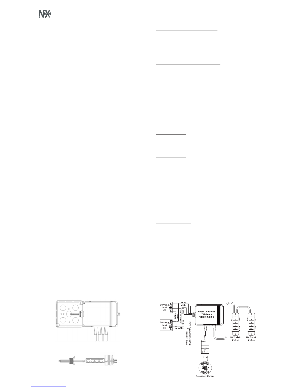
3. Mount the Room Controller (RC) to the outside of a junction box using the Room
Controller’s extended ½” chase nipple. Secure to box with enclosed EMT nut. (See
Figure 1)
4. The Room Controller has a MAC address label affixed to the outside of the unit. Place
the enclosed MAC address label(s) in a log book and record the location of the Room
Controller and the circuit(s) it controls. The MAC address will be needed later during
the system setup process.
5. If control devices (e.g. occupancy sensors, daylight sensor and switches) are going to
be used, attach them to any available Smart Port with the appropriate CAT5 device
cable. Similar devices (e.g. switches) may be daisy chained together from the same
Smart Port. ( See Figure 2)
6. Electrically connect the Room Controller to the circuit(s) as shown in Figure 3. Reapply
power at service panel.
7. Test installation as follows:
a. Momentarily press Button A to toggle Load A (red wire) ON and OFF
b. Momentarily press Button B to toggle Load B (blue wire) ON and OFF (2 Relay
Models Only)
c. With Load A ON, press and hold Button A down to dim Load A down.
Release Button A and press again to dim Load A up.
d. With Load B ON, press and hold Button B down to dim Load B down.
Release Button B and press again to dim Load B up.
OPERATION GUIDE
The NX Room Controller is designed to control and manage lighting within a single room
or zone in a building. Working in conjunction with an occupancy sensor(s), daylight sensor,
and wall switch station(s), the room controller intelligently responds to inputs to perform
the required lighting control sequence of operation. The room controller operates with the
connected control devices as a stand-alone local control system but can be extended to
participate in a building-wide networked lighting control system with the addition of the
NXHNB Network Bridge Module.
NETWORKED
Lighting Controls
TM
Figure 1: Room Controller mounted to 4x4 junction box
Figure 2: Room Controller SmartPORTs – Connect control devices (e.g. occupancy sensors, daylight sensor and switches) to any available Smart Port
Figure 3
CONNECTING MULTIPLE ROOM CONTROLLERS
Room controllers can be inter-connected to expand the number of relays and dimmers in
the room or to allow the use of more than one voltage. Use CAT5 cable(s) to connect the
room controllers in a daisy chain configuration. That is, no more than one RJ45 port in each
room controller should be used for this connection. A maximum of 8 room controllers may
be connected for a maximum of 16 relays and 16 dimmers. Self configuration will function
normally up to a maximum of 6 loads. Manual configuration will be required beyond 6
loads.
CONNECTING LOW VOLTAGE CONTROL DEVICES
The Room Controller provides a source of 24 VDC current to power the connected control
devices such as switch stations and sensors. A maximum of 250 mA of 24 VDC current is
available. Since the control components draw differing amounts of current, the following
table should be used to determine how many control devices can be connected to a single
room controller. In cases where two or more room controllers are connected together, the
power budget is determined for each room controller based on the control devices that are
plugged into that room controller. See Figure 3.
MAXIMUM POWER BUDGET PER ROOM CONTROLLER = 30 LOADS
Switch station = 1 Load
PIR only Occupancy sensor = 1 Load
PIR only Occupancy sensor with RP option = 2 Loads
Dual Technology and Ultrasonic Occupancy sensor = 3 Loads
Dual Technology and Ultrasonic Occupancy sensor with RP option = 4 Loads
Daylight Sensor (photocell) = 1 Load
NOTE: Only one daylight sensor can be connected in each room/zone
SELF CONFIGURATION
The sequence of operation in the room will automatically reconfigure as devices are
plugged into the room controller as described in the following sections. Note that self
configuration will automatically be disabled once the room has been maunally configured.
See Manual Configuration section.
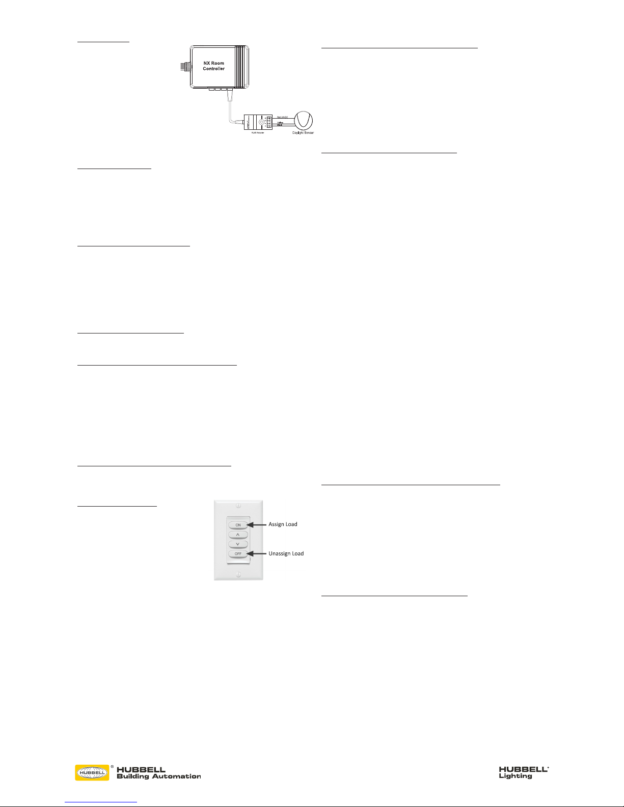
OCCUPANCY SENSORS
The NX room controller is compatible with any low voltage Hubbell Building Automation
vacancy/occupancy sensor that uses the red/black/blue control wires. A wiring adapter
(RJ45ADAPTOR) is required to make the wiring transition from the flying leads on the
sensor to the RJ-45 Smart Port on the room controller. Hubbell Building Automation
sensors ordered under model NXOS series model numbers are automatically supplied with
the adapter and a short CAT5 jumper cable.
The sensor can be connected to the Room Controller Smart Port using a pre-terminated
CAT5 cable (see Figure 3). Alternately, the adapter can be connected to the Room
Controller Smart Port and one or more sensors connected using traditional low voltage
wiring. The adapter is color coded to match the flying leads on the sensors.
NOTE: Once any NX digital switch station is connected to the Room Controller, the mode
of operation will automatically switch to vacancy mode (manual on) for all loads. To
change one or more load(s) to automatic on operation see Manual Configuration section.
DIGITAL SWITCH STATIONS
The NX Digital Switch Stations will automatically configure themselves to control the
available loads within 5 seconds after being connected to the Room Controller. For best
results, do not press any buttons for 5 seconds after plugging in a switch station. This allows
time for the system to self configure and stabilize.
Model number switch stations NXSW-1, NXSW-2, NXSW-3, NXSW-4, NXSW-6 will have
all buttons configured for ON/OFF toggle operation by default. These stations will self
configure to sequentially control the loads. For example, a NXSW-1 will control load 1, a
NXSW-2 will control loads 1 and 2, etc. The relationship between the buttons and the loads
can be changed. See Manual Configuration section. NOTE: If the zone has more loads
than buttons, the last button in the sequence will automatically control the remaining
loads. This insures that no load is left uncontrolled during the self configuration process.
The NX Specialty Switch Stations model NXSW-OO and NXSW-TO will self configure the
same as the NXSW-1 as described above.
The NX Specialty Switch Stations model number NXSW-RL, NXSW-SS and NXSW-ORLO
have dimming functionality and will self configure to control all loads. The relationship of
the stations to the dimmed loads can be changed. See Manual Configuration section.
* See addressing Instructions
provided with the NXSW Switches
for “Daisy Chain” series connection
installation.
* *
Page 2
72-00567 REV C
9601 Dessau Road, Building One | Austin, TX 78754 Toll Free: 888-698-3242 | Fax: 512-450-1215 | www.hubbell-automation.com
DAYLIGHT SENSOR
The model NXDS Daylight Sensor will
self configure to control Load 1 when
connected to a room controller. The
daylight sensor will become active 30
seconds after the load has been turned
on. The photocell operation can be
verified by observing Load 1 lighting
while alternately covering the photocell
(Load 1 light will be ON and bright
if dimming enabled) or exposing the
photocell to bright light (Load 1 light
will be OFF or dimmed if so enabled).
The relationship between the daylight sensor and the load(s) can be changed. See Manual
Configuration section.
MANUAL CONFIGURATION
The process of manual configuration allows certain functions to be adjusted using only the
A and B pushbuttons and LED indicators on the Room Controller. The functions that can be
adjusted are:
1. Assign loads to buttons and stations
2. Configure loads for manual ON (vacancy mode) or automatic ON operation
3. Configure loads to respond to the photocell
4. Calibrate the photocell
ENTER MANUAL CONFIGURATION MODE
To enter manual configuration mode, simultaneously press and hold buttons A and B on the
Room Controller until the A and B LEDs start to alternately blink. Release buttons A and B.
The room controller will now be in configuration mode. Load A will be ON and all other loads
will be OFF. Note, while in configuration mode no more than one load will ever be on and
the A and B buttons on the room controller will not control the loads.
Hint: If more than one load is on or pressing the A or B button switches the associated load,
you likely did not press both buttons exactly together when entering configuration mode.
Repeat the process to enter manual configuration mode.
EXIT MANUAL CONFIGURATION MODE
To exit configuration mode, simultaneously press and immediately release buttons A and B.
The room controller will resume normal operation.
ENTER MANUAL CONFIGURATION MODE FROM A SWITCH
Remove the faceplate from any wall switch and locate the rectangular opening in the plastic
bezel marked “SVC PIN”. Use a thin object such as a straightened paper clip to press the
recessed configuration button for 5 seconds. Note that the button is located slightly offset
from the opening in the bezel. The LED marked “SVC” will blink while the configuration
button is being pressed. Release the configuration button and note that one load turns on
and all other loads turn off indicating that the room is in manual configuration mode.
Hint: You may find it more convenient to remove the plastic bezil from the switch during
programming. Simply pry off using the notch at the bottom. To reattach, insert the tabs at
the top and snap into place at the bottom.
EXIT MANUAL CONFIGURATION MODE FROM A SWITCH
Press the configuration button for five seconds. Note that the LED marked “SVC” will blink
while the configuration button is being pressed. Release the configuration button. The loads
in the room will restore to the levels they were prior to entering manual configuration mode.
ASSIGN LOADS TO BUTTONS
All NXSW switch stations assume default
operation of the load(s) when they are plugged
into a Smart Port on the Room Controller. The
assignment of the loads to the buttons can easily
be changed as follows:
Enter configuration mode as described above.
Load A on the first room controller will be ON.
While load A is ON, each button that controls
that load will have a lighted LED. To unassign
control of the load from the button, press the button to extinguish the LED. To assign the
load to another button, press the switch station button to light the LED on the button. Repeat
this process for all buttons.
To advance to the next load, press and release button A on the room controller. Load A will
turn off and next load will turn ON. Repeat the assignment process above for each load.
For NXSW switch stations that do not have LED indicators, ie. NXSW-OO, NXSW-ORLO,
NXSW-RL, etc., press the ON button or the Raise button to assign the load. Press the OFF
button or the Lower button to unassign the load.
If using the Switch Station method for manual load configuration, tap the recessed
configuration button to advance to the next load as necessary.
After all loads are assigned, exit manual configuration mode. Test the button operation and
repeat the above if necessary.
CONFIGURE LOADS FOR AUTO/MANUAL ON OPERATION
Enter manual configuration mode (see above). While load A is ON, the B LED on the room
controller will indicate the current operation mode for the load. If LED B is OFF, the load
will operate in manual on (vacancy) mode. If LED B is ON, the load will operate in auto ON
mode when the motion sensor detects occupancy. Press and release button B on the room
controller to change the operation mode for the current load.
To advance to the next load, press and release button A on the room controller. Repeat the
above for all loads. When finished, exit manual configuration mode.
Hint: A load set to manual ON (vacancy mode) must be controlled by an NXSW wall
switch station otherwise the load will never turn on.
CONFIGURE LOADS FOR PHOTOCELL OPERATION
Enter manual configuration mode. While in manual configuration mode, simultaneously
press and hold buttons A and B for three seconds until the A and B LED begin to alternately
blink. This indicates the room controller has transitioned from load configuration mode into
photocell configuration mode. While in photocell configuration mode, only one load will
be ON. If the selected load has dimming capability, the light will cycle between minimum
to maximum to identify itself during the selection process. If the currently selected load is
to be controlled by the photocell, momentarily press and release button B on the room
controller. LED B will blink in a pattern to indicate the performance level for daylight
harvesting.
The blink patterns are as follows:
Double blink/pause indicates normal baseline performance (default setting)
Triple blink/pause indicates more aggressive performance, lights will dim more
Single blink/pause indicates less aggressive performance, lights will dim less
No blinking indicates that the selected load will not participate in daylight harvesting
NOTE: During this process, the load will dim to high, medium or low refelcting the
currently selected performance as indicated by the LED blink patern.
Press and release button B on the room controller to cycle through the performance choices
for the selected load. The
“more aggressive” selection will cause the light to dim more during daylight harvesting.
The “less aggressive” selection will cause the light to dim less.
Hint: If the room controller is equipped with dimming capability (NXRC-1RD or NXRC2RD), the photocell will assume that it’s operation will use dimming. If the room controller
does not have dimming capability (NXRC-1R or NXRC-2R), the photocell will operate in
switching mode based on a default set point of 150 foot candles.
Press and release button A on the room controller save your selection and to advance to
the next load. Repeat the above to set the performance for all loads to be controlled by
the photocell. Proceed to auto calibration of the photocell.
Hint: the above process can be used to set up multi-zone daylight harvesting in applications
where more than one row of lights are to be controlled. Simply select a more aggressive
performance for the row closest to the windows and a less aggressive performance for the
row away from the windows. Using this process it is possible to set up a room with three
zones of daylight harvesting using the triple blink setting for the row by the window, the
double blink setting for the row in the center, and the single blink setting for the row away
from the window.
RESET THE ROOM CONTROLLER TO FACTORY DEFAULT SETTINGS
Should you wish to erase all manual configuration and restore the room controller to its
factory default settings, perform the following step:
Simultaneously press and hold buttons A and B on the room controller. After a few seconds,
LED A and B will begin alternately blink. Continue to hold buttons A and B until the blink
pattern changes to a double blink pattern. Release buttons A and B. When the blinking
stops, all loads will turn on indicating the room controller has be reset to factory default
settings. After a reset, the room wil auto configure based on the connected devices.
Hint: If the installation has more than one room controller connected together in the
room, the reset process done on any one of the room controllers will reset all of the room
controllers.
RESET FACTORY DEFAULTS USING A SWITCH STATION
Remove the faceplate from any wall switch and locate the rectangular opening in the plastic
bezel marked “SVC PIN”. Use a thin object such as a straightened paper clip to press the
recessed configuration button for at least 10 seconds. Note that the button is located
slightly offset from the opening in the bezel. The LED marked “SVC” will blink while the
configuration button is being pressed. Release the configuration button and note that all
loads in the room turn on indicating that the room has been reset to factory default settings.
Assign Load
Unassign Load
NXSW-ORLO
Figure 4
 Loading...