

Page 1

wiSCAPE™ GATEWAY
TM
INSTALLATION INSTRUCTIONS
PRECAUTIONS
• Read and understand all instructions before beginning installation.
• NOTICE: For installation by a licensed electrician in accordance with National and/or local Electrical Codes and the following
instructions.
• Disconnect switch or a circuit breaker must be provided and marked as the disconnecting device.
• Disconnect switch / circuit breaker must be within reach of operator.
• CAUTION: RISK OF ELECTRICAL SHOCK. Turn power o at service panel before beginning installation. Never wire energized
electrical components.
• CAUTION: USE COPPER CONDUCTOR ONLY
• Conrm device ratings are suitable for application prior to installation. Use of device in applications beyond its specied ratings or
in applications other than its intended use may cause an unsafe condition and will void manufacturer’s warranty.
• NOTICE: Do not install if product appears to be damaged.
SAVE THESE INSTRUCTIONS!
DESCRIPTION
Hubbell Controls’ wiSCAPE™ Gateway is used to combine up to 1000 wiSCAPE Fixture Modules into a single wireless network. Although
each Fixture Module is functionally autonomous, the Gateway also acts as an access point through which the modules can be managed,
monitored, and metered through wiSCAPE View™ software. Using the robust 2.4GHz ISM (Industrial, Scientic and medical) radio
frequency, the wiSCAPE Gateway wireless control technology adapts easily to complex automation situations for quick, simple and
economical commissioning and operation.
SPECIFICATIONS
Operation range 120-240V; 50/60Hz
277/347 required use of step down transformers WIR-STPDNXFMR-277 or 347
Power consumption 18 watts
Fused supply 5 amps
Surge protection 190 Joules (10,000 surge current rating measured using industry standard 8/20 μSec wave)
50/60 HZ, Consumption: max 26 VA
0
Ambient temperature range -40
Relative humidity Up to 99% non-condensing (fully waterproof enclosure (NEMA 4x)
Dimensions 12”L x 14”W x 6”H
Construction Compression molded berglass reinforced polyester construction with ush,
solid/opaque cover, IP66 Rated
Certications FCC/IC Certied, RoHS Compliant
Warranty Five-year limited warranty
F to 1850F (-400C to 850C)
9601 Dessau Road, Building One | Austin, TX 78754 Toll Free: 888-698-3242 | Fax: 512-450-1215 | www.hubbell-controls.com 4501B 07.15.2016 Rev B
Page 2
INSTALLATION
1. Turn power o at the service panel.
2. Use appropriate hardware to mount the GATEWAY to the intended structure.
3. Drill or punch an appropriate hole for the power cable. A weatherproof strain relief should be used (customer-supplied) .
4. Mount the GATEWAY in the installation site.
5. Secure the enclosure to prevent any damage. Make sure that enclosure stands upright, the door hinges located on the left of the
enclosure.
6. Attach the external antenna to the GATEWAY.
7. LINE VOLTAGE WIRING: Remove 5/8” (1,6cm) of insulation from each circuit conductor. Make sure that ends of conductors are
straight.
8. Connect lead wires according to the wiring diagram below.
9. Electrically connect the device to the circuit as shown in the Wiring Diagram below.
10. Make sure that a proper fuse is present in the fuse holder and that fuse holder is closed. Restore power at circuit breaker or fuse.
11. Reapply power at service panel.
12. LED Indicators:
GREEN LED on DC power supply means that the DC power is okay.
GREEN LED on PC indicates that it is correctly powered and running.
GREEN LED on GPRS modem indicates that it is correctly powered and running.
GREEN LED on USB Modem that it is correctly powered and running.
13. Perform system setup and/or programming activities as applicable in accordance with the instructions of the wiSCAPE View™
programming device.
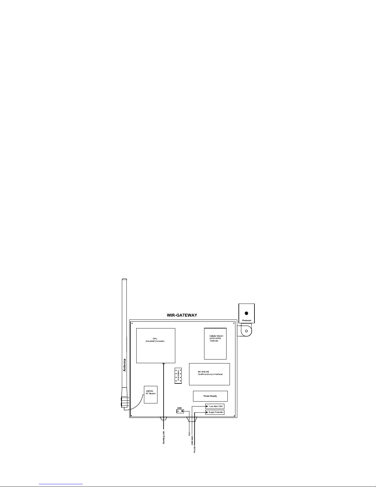
WIRING DIAGRAM
Page 2
 Loading...