

Page 1
OPERATION
"AC ON" LED is illuminated when AC power is present.
NOTE: All models are supplied with an AC Lockout Circuit, which prevents the "EXIT" legend from illuminating when the battery is connected and no AC power is present.
NOTE: All models are supplied with a Low Voltage Disconnect circuit, which prevents damage to the battery from deep discharge during prolonged emergency operation.
NOTE: Batteries are often shipped in a discharged state this is normal. The battery will require charging. Allow several hours of charge before testing the unit.
Models With SPECTRON® SelfTesting/SelfDiagnostic Circuitry
Models equipped with the SPECTRON selftesting/selfdiagnostic electronics system provide:
■ Visual indication of AC power status ■ Visual indication of selfdiagnostic test cycle
Visual indication of any unit malfunctions including:
■ Battery disconect
■ Battery fault ■ Transfer fault ■Charger fault ■ Emergency Lamp fault
Spectron equipped units also include:
Brownout protection: unit will automatically transfer to emergency operation upon detection of low AC power (aproximately 80% of normal line).
Time Delay Retransfer: upon return of normal AC power, unit will remain in the emergency mode for an additional 15 minutes to allow AC power to stabilize.
LED Status Indicator
A bicolor LED (red/green) is provided on the control panel of all models equipped
with Spectron option.
Green Operating Status Indicator
The green Operating Status Indicator serves as both an AC power and selftest
indicator. During normal operation, the green Operating Status Indicator will be
illuminated, indicating the presence of AC power. During all automatic or manual
selftest cycles, the green Operating Status Indicator will blink at a 1 Hz rate.
Red Service Alert Indicator
Under normal operating conditions, the red Service Alert Indicator will remain off.
In the event the Spectron controller detects a malfunction, the red Service Alert
Indicator will blink at a 1 Hz rate, based on the following table:
Red Status Indi cator Code Descript ion
One blink ON/pause Battery not connected
Two blinks ON/pause Battery fault
Three blinks ON/pause Charger fault
Four bli nks ON/pause Transfe r circuit fa ult
Five blinks ON/pause Emergency Lamp fault
Manual Tests
Using the unit test switch, users can initiate different duration test cycles
based on the following table:
Automatic Tests
The unit will automatically initiate a selftest/selfdiagnostic cycle based
on the following table:
Initiating Action Test Cycle
Pre ss test sw itch once 1 minute
Press test sw itch twice
90 min utes
Testi ng Period Duration of Test
Once a month 1 minute
Once e very 6 mont hs
Alternating:
30 min utes o r 60 minut es
MAINTENANCE
TROUBLE SHOOTING
● "EXIT" legend does not illuminate
check wiring connections
● Emergency Circuit does not work
Batteries are shipped uncharged and disconnected. Connect power pack leads charge before testing.
Make sure charger board is properly seated.
Check wiring connections.
MAINTENANCE
Signs should be tested and maintained in accordance with National Electrical Code and NFPA 101 Life Safety Code requirements. It is recommended that emergency exit
signs be tested for 30 seconds once a month and for 90 minutes once a year.
RECYCLING INFORMATION
All thermoplastic parts are recyclable.
All cartons contain recycled materials.
Please recycle responsibly.
NOTICE:
Emergency model exit signs contain rechargeable Nickel Metal Hydride batteries which must be recycled or disposed of properly.
Hubbell Lighting, Inc. Life Safety Products • www.duallite.com
Copyright© Hubbell Lighting, Inc., All Rights Reserved • Specifications subject to change without notice. • Printed in U.S.A.
IMPORTANT SAFEGUARDS
When using electrical equipment, basic safety precautions should always be followed including the following:
READ AND FOLLOW ALL SAFETY INSTRUCTIONS
1. Do not use outdoors.
2. Do not let power supply cords touch hot surfaces.
3. Do not mount near gas or electric heaters.
4. Equipment should be mounted in locations and at heights where it will not readily be subject to tampering by
unauthorized personnel.
5. The use of accessory equipment not authorized by the manufacturer may cause an unsafe condition.
6. Do not use this equipment for other than its intended purpose.
7. Servicing of this equipment should be performed by qualified service personnel.
8. Test cycling: the Life Safety Code (NFPA 101) requires testing of emergency exit signs once a month for a
minimum of 30 seconds and once a year for a minimum of 90 minutes
.
INSTALLER:
• SEE UNIT LABLE FOR ADDITIONAL MODEL SPECIFICATIONS
• SAVE THESE INSTRUCTIONS FOR USE BY OWNER/OCCUPANT
WARNING This product contains chemicals known to the State of California to cause cancer, birth defects, and/or other reproductive harm.
Thoroughly wash hands after installing, handling, cleaning, or otherwise touching this product.
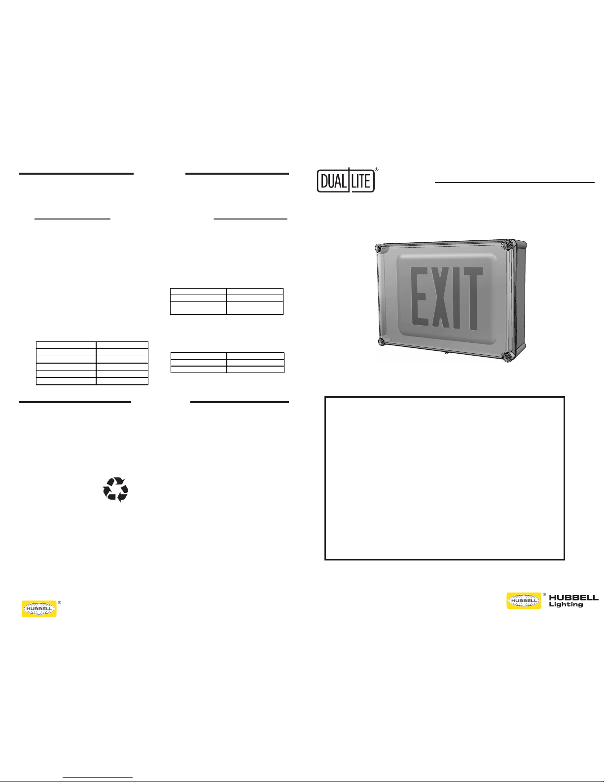
EVE Series
Thermoplastic LED Exit Sign
Installation, Operation, and Maintenance Instructions
ALBALBEC-1608310019/15/161
2 1
D
C
B
REV DATE RECORD DESN CHCK
Emergency LED Exit Sign Listed for Wet locations
AC, Emergency & Spectron Emergency rated N4X/IP66
Installation, Operation, and Service Instructions
EVE4X Series
OPERATION
93075008 B 5/1/17
93075474
MAINTENANCE
IMPORTANT SAFEGUARDS
When using electrical equipment, basis safety precautions should always be followed
including the following.
READ AND FOLLOW ALL SAFETY INSTRUCTION
1. Do not let power supply cords touch hot surfaces.
2. Do not mount near gas or electric heaters.
3. Equipment should be mounted in locations and at height where it will not readily
be subjected to tampering by unauthorized personnel.
4. The use of accessory equipment not authorized by the manufacturer may cause an
unsafe condition.
5. Do not use this equipment for other than its intended purpose.
6. Servicing of this equipment should be performed by qualied service personnel.
7. Test cycling: the Life Safety Code (NFPA 101) requires testing of emergency exit signs
once a month for a
minimum of 30 seconds and once a year for a minimum of 90 minutes.
INSTALLER
• SEE UNIT LABEL FOR ADDITIONAL MODEL SPECIFICATIONS
• SAVE THESE INSTRUCTIONS FOR USE BY OWNER/OCCUPANT
WARNING: - This product contains chemicals known to the State of California to cause
cancer, birth defects and/or other reproductive harm. Thoroughtly wash hands after
installing, handling, cleaning or otherwise touching this product.
Page 2
INSTALLATION INSTRUCTIONS INSTALLATION INSTRUCTIONS
ALBALBEC-1608310019/19/161
4 3
2 1
D
C
B
REV DATE RECORD DESN CHCK
4 5
3" TYP.
5" TYP.
1-1/4"
TYP.
4
5
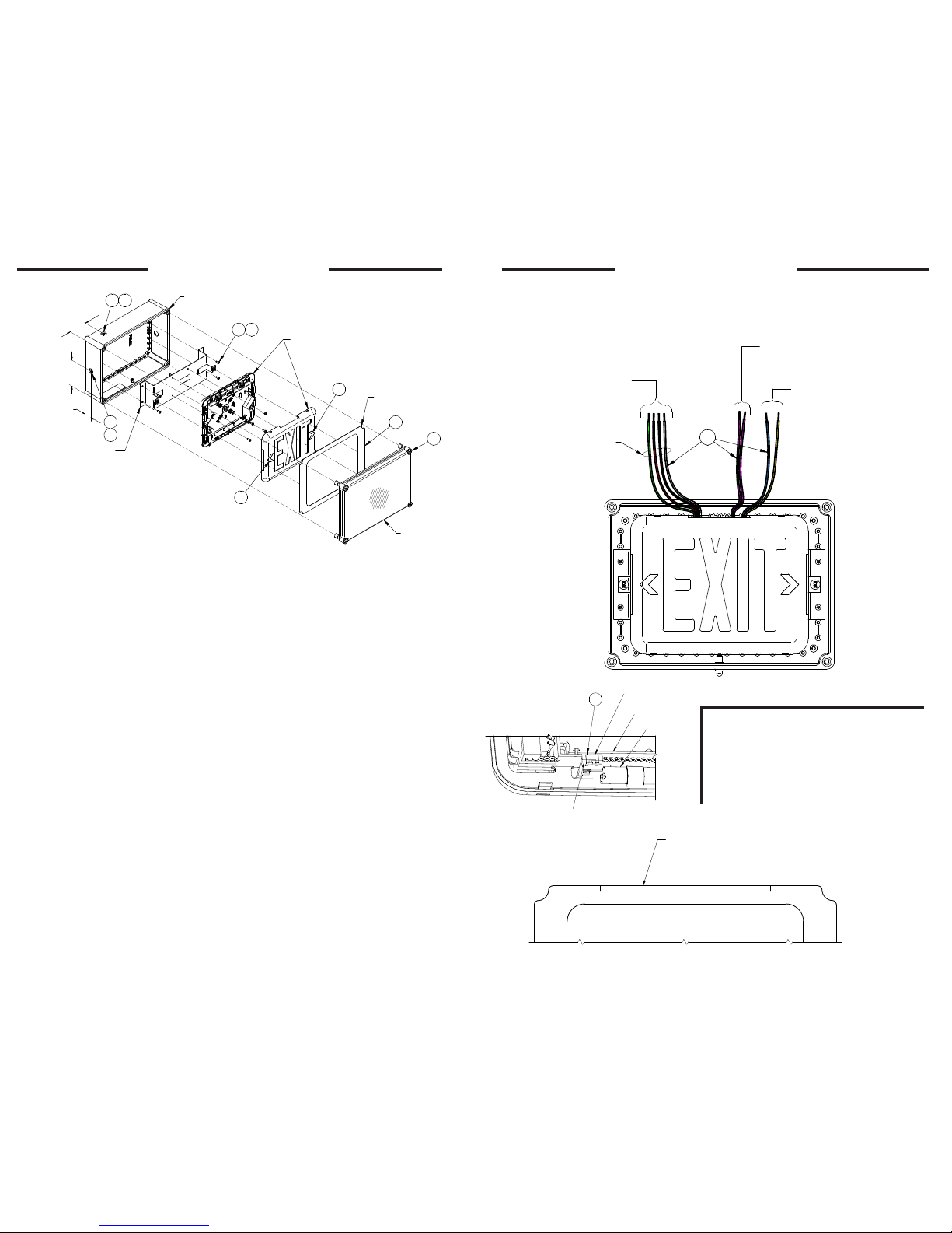
ENCLOSURE
EXIT SIGN
MTG BRKT
EXIT
SIGN
TRIM PLT
CLEAR
COVER
93075569
FIG. 1
3 6
9
2
1
9
STEPS:
1. Loosen the four slotted captive cover screws and remove the clear cover (qty 4).
2. The white trim plate surrounding the exit sign face is held in place by "hook and loop"
velcro, located on the underside of the trim plate. Remove the trim plate by carefully
lifting straight up to disengage the velcro.
3. Remove the exit sign and mounting bracket by removing 4 bracket mtg plate screws
(qty 4) before proceeding to step 4.
4. If needed, drill the appropriate size hole to dim's shown for conduit entry.
5. Only use UL Listed water tight conduit fittings that meet the requirements of the
UL 514B Standard for Conduit Tubing and Cable. Route building utility conductors
through conduit and into enclosure.
6. Reinstall mounting bracket and exit sign. Remove exit sign front face from housing
before proceeding to step 7.
7. Make all connections to building utility AC conductors using color coded leads
provided. ( See Fig. 2)
8. For em models, connect the battery as shown. (see Fig. 3).
9. Snap-in appropriate chevron arrows in exit stencil face , if required.
10. Energize the AC power to the exit sign.
NOTE: For emergency models, allow the battery to fully charger before testing.
ALBALBEC-1608310019/19/161
4 3
2 1
D
C
B
REV DATE RECORD DESN CHCK
WIRING DIAGRAM
120/277VAC
AC, EMERGENCY
FIG. 2
93075570
INSULATE UNUSED
RED OR BLK LEAD
TO PREVENT
ELECTRIC SHOCK
To Building Utilit y
120 or 277 VAC
120VAC-CONNECT BLACK & WHITE WIRE
277VAC-CONNECT RED & WHITE WIRES
TRANSFORMER GROUND-GREEN WIRE
-FAP OPTION 24V AC OR DC
(IF APPLICABLE)
TO FIRE ALARM SYSTEMS
CONNECT BOTH VIOLET WIRES
-DC OPTION (IF APPLICABLE)
TO REMOTE DC POWER
SOURCE (6-24VDC)
YELLOW(-) & BLUE (+) WIRES
7
ALBALBEC-1608310019/19/161
2 1
D
C
B
REV DATE RECORD DESN CHCK
EMERGENCY MODEL
BATTERY CONNECTION
8
Battery
Connector
Charger PCB
Battery
Plug battery connector
onto 2-pin PCB header
93075573
FIG. 3
IMPORTANT: This sign may be equipped with one
or more options. Check model number suffix for
option designation.
-FAP OPTION (Fire Alarm Panel) FAP option connects to 24 volts AC or DC (purple wires). Flash Rate
.5 seconds on, .5 seconds off.
-DC OPTION (-DC Remote Option) DC Remote option connects to 6-24 volt DC Yellow(-), blue (+).
-FM OPTION (FLasher Module) Emergency Mode
Flash Rate: .5 seconds on, .5 seconds off.
ALBALBRELEASED, EC-1608310016/13/17A
2 1
D
C
REV DATE RECORD DESN CHCK
93085892
If bezel pulls away from exit sign
on the top and bottom customer
can remove adhesive backing and
press lightly on bezel once affixed
to exit if needed!
 Loading...