

Hubbell Heaters J4 Service Manual
OPERATING AND MAINTENANCE
MANUAL FOR
ELECTRIC BOOSTER HEATER
ELECTRIC HEATER COMPANY
BASE MODEL “ J ”
2014 Edition Rev. A
UM ANSI/NSF5
1

HUBBELL
ELECTRIC HEATER COMPANY
45 SEYMOUR STREET
P.O. BOX 288
STRATFORD, CT 06615
PHONE: (203) 378-2659
FAX: (203) 378-3593
INTERNET: http://www.hubbellheaters.com
-- IMPORTANT --
ays reference the full model number and serial number when calling the factory.
Alw
WARNING / CAUTION
1. Tank is to be completely filled with water and all air is to
be vented before energizing.
2. Due to the rigors of transportation, all connections should be checked for tightness before
heater is placed in operation.
3. Safety relief valve m
ust be
4. The refractory material used in heating elem
transit, periods of storage, or when subjected to a hum
absorption results in a cold insulation resistance of less than twenty
heater has been subjected to the above condition, each heating elem
installed in tapping provided.
ents may absorb some mo
id environment. This mo
isture during
isture
(20) megohm
ent mu
st be checked
s. If this
for insulation resistance before energizing. Contact the factory for a replacement element.
5. KEEP AWAY FROM LIVE ELECTRICAL CIRCUITS.
Do not perform
any maintenance, make any adjustments, or replace any com
ponents
inside the control panel with the high voltage power supply turned on. Under certain
circum
stances, dangerous potentials may exist
even when the power supply is off. To
avoid casualties, always turn the power supply safety switch to off, turn the charge or
ground the circuit before perform
ing any maintenance or adjustme
nt procedure.
6. The unit is designed to operate at pressure not more than 150 psi.
7. Generalized instructions and procedures cannot anticipate all situations. For this reason,
only qualified installers should perform
the in
stallations. A qualified installer is a person
who has licensed training and a working knowledge of the applicable codes, tools,
equipm
ent, and methods necessary for safe
installation of an electric resistance water
heater. If questions regarding installation arise, check your local plumbing and electrical
inspectors for proper procedures and codes. If you cannot obtain the required
information, contact the company.
8. Water Quality Requirements – Recommended wa
ter hardness is 4 to 6 grains of
hardness per gallon (GPG). Water hardness above 6 GPG should be treated by a water
conditioner (water softener or in-line treatment). Water hardness below 4 GPG also
requires treatm
operating and m
ent to reduce potential corrosi
on. Excessive GPG will result in higher
aintenance costs and will reduce product longevity. Chlorides mu
st
not exceed 50 parts per million (ppm). Excessive chlorides will result in metallic
corrosion and will reduce product longevity. Water treatment has been shown to
reduce costs associated with de-lim
ing the booster as well as reducing me
tallic
corrosion. Product failure caused by these conditions is not covered under warranty.
See warranty for complete details.
9. This water heater is not intended for space heating applications.
10. The water heater is factory set at 185°F for booster water heating applications. This
results in the possibility of a scalding water injury. A full thickness skin burn can
occur in less than one second of exposure to water at this temperature.
2

TABLE OF CONTENTS
SECTION TITLE
I GENERAL DESCRIPTION AND CONSTRUCTION 4
II INSTALLATION AND START-UP 9
III SCHEDULED MAINTENANCE AND OPERATION 24
IV TROUBLESHOOTING 26
V SERVICING AND REPLACEMENT OF PARTS 32
VI SERVICE PARTS LIST 35
VII TORQUE VALUES 37
VIII WARRANTY INFORMATION 38
PAGE No.
3

SECTION I - GENERAL DESCRIPTION AND CONSTRUCTION
GENERAL DESCRIPTION
This book describes a packaged electric booster heater that is typically used to provide 180°F
sanitizing rinse water. The complete assembly consists of the storage tank, immersion electric
heating element(s), electronic control module, safety relief valve, magnetic contactor(s), and
any other required electrical operating control. Optional equipment may be supplied with your
unit. Please consult the product packing list for details specific to your assembly. The unit is
factory assembled, insulated, jacketed, wired, tested, and ready for electrical and plumbing
service connections.
CAPACITY
Storage
Model
J32.9 3 2.9 30 17 J161 16 1 10 5
J35.7 3 5.7 58 33 J161.5 16 1.5 15 8
J39.9 3 9.9 101 58 J162 16 2 20 11
J310.4 3 10.4 107 61 J163 16 3 30 17
J311.4 3 11.4 117 67 J164 16 4 41 23
J411 4 11.4 117 67 J166 16 6 62 35
J415 4 15 154 88 J167 16 7 72 41
J427 4 27 277 158 J169 16 9 92 53
J61 6 1 10 5 J1612 16 12 123 70
J61.5 6 1.5 15 8 J1613 16 13.5 138 79
J62 6 2 20 11 J1615 16 15 154 88
J63 6 3 30 17 J1618 16 18 185 105
J64 6 4 41 23 J1624 16 24 246 141
J65 6 5 51 29 J1627 16 27 277 158
J66 6 6 62 35 J1630 16 30 308 176
J67 6 7 72 41 J1636 16 36 369 211
J69 6 9 92 53 J1639 16 39 400 228
J610 6 10.5 108 62 J1640 16 40.5 415 237
J612 6 12 123 70 J1645 16 45 461 264
J613 6 13.5 138 79 J1654 16 54 554 316
J615 6 15 154 88 J1658 16 58.5 600 343
J618 6 18 185 105 J1664 16 64 656 375
J624 6 24 246 141 J1666 16 66 677 387
J627 6 27 277 158 J1668 16 68 697 398
J630 6 30 308 176 J1679 16 79 810 463
J636 6 36 369 211 J1681 16 81 830 474
J639 6 39 400 228 J1685 16 85 871 498
J640 6 40.5 415 237 J1686 16 86 882 504
J645 6 45 461 264 J1688 16 88 902 515
J654 6 54 554 316 J1690 16 90 923 527
J658 6 58.5 600 343
Capacity
(gallons)
kW
40°F
Rise
(GPH)
70°F
Rise
(GPH)
Model
Storage
Capacity
(gallons)
kW
40°F
Rise
(GPH)
70°F
Rise
(GPH)
4
56 7

CONSTRUCTION
TANK
The storage tank is designed, manufactured, and stamped in accordance with ASME Section
VIII, Division 1. The tank is constructed of type 304L stainless steel for maximum tank
longevity and fabricated by all welded construction and is designed for a maximum allowable
working pressure of 150 psi (225 psi test pressure).
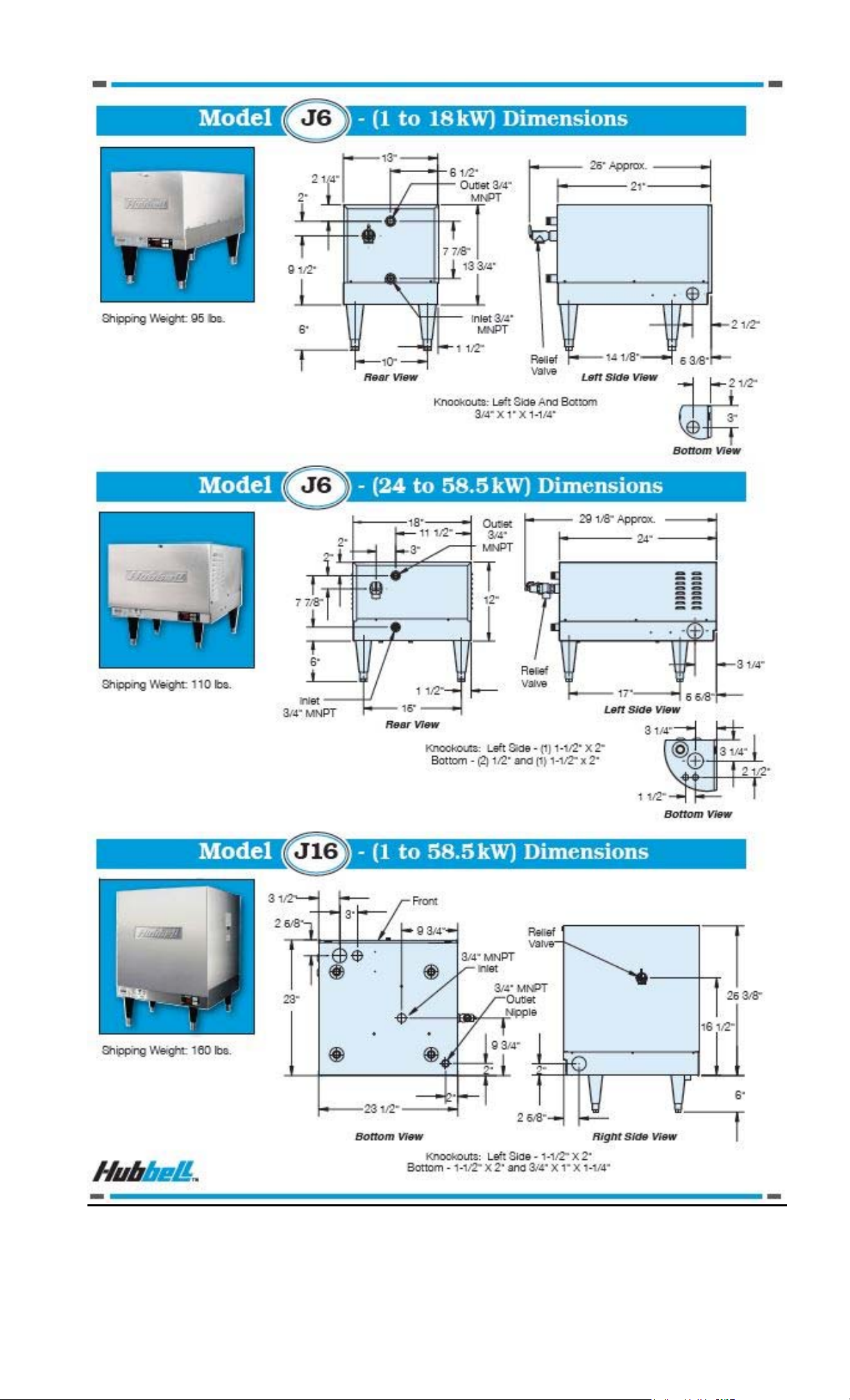
TANK CONNECTIONS
The heater is supplied with separate connections for the cold/warm inlet and the hot water
outlet. Water entering the warm water inlet and leaving through the hot water outlet is evenly
circulated by means of a diffuser within the tank. A ¾-inch FNPT connection is provided for
mounting a combination temperature and pressure safety relief valve. An overflow line should
be utilized from the relief valve outlet to a floor drain. See drawing for locations and sizes.
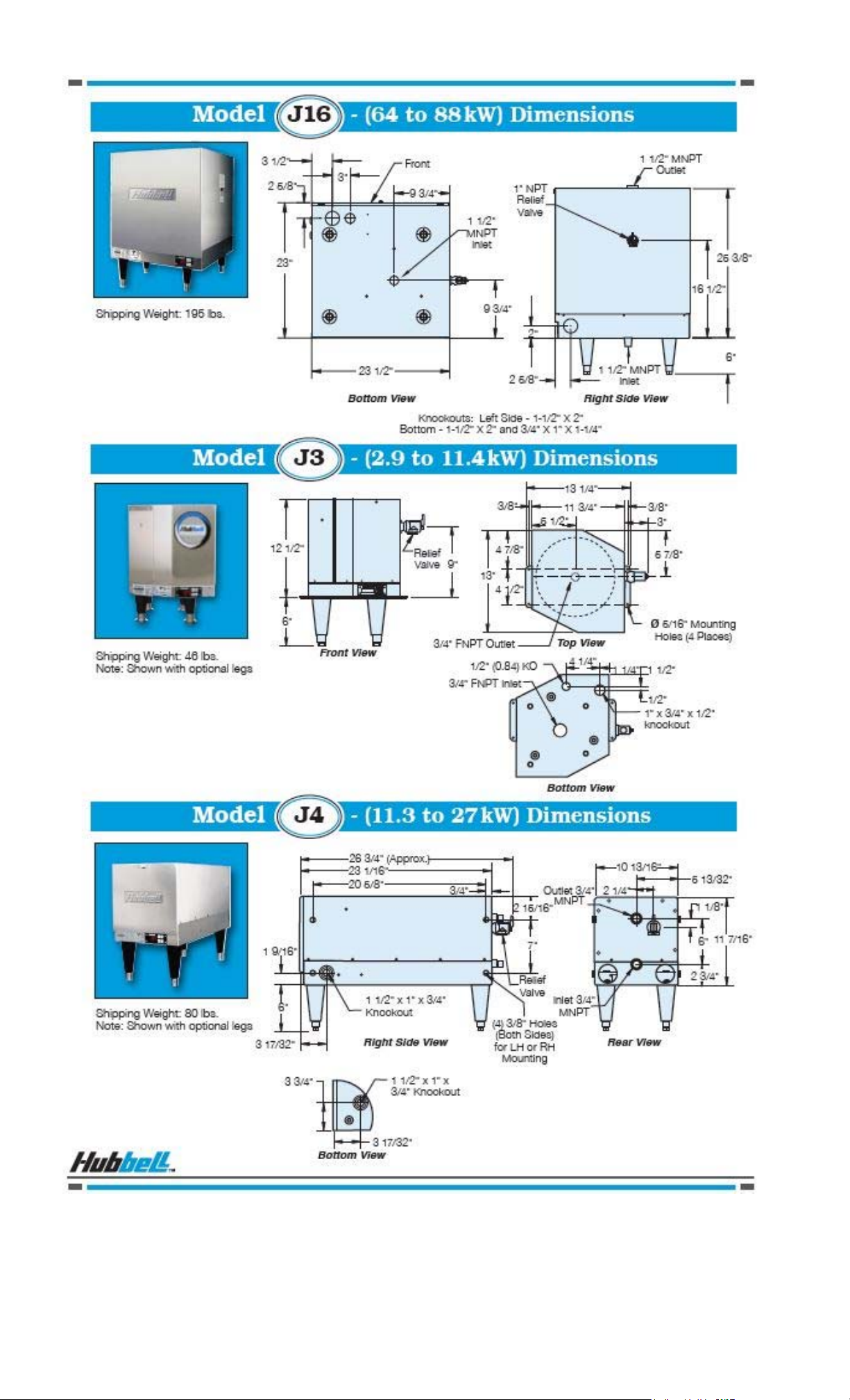
HEATING ELEMENT
The water heater is supplied with an electric
immersion heating element assembly(s), composed
of corrosion resistant sheathed elements that are
fitted into a 1½-12UNF brass screw plug with a
1⅞” hex. Each assembly is threaded into the tank and sealed with an o-ring gasket. See drawing
for voltage and power ratings. Note that the J3 model element is a 1” NPS thread with a 1½”
hex.
MAGNETIC CONTACTOR
Load switching is done by a heavy-duty resistive (non-inductive)
load type definite purpose magnetic contactor. The contactor supplies
power to the heating element(s) when the relay on the control board
is closed, thereby pulling in the contacts until the desired temperature
is reached. At this point, the contacts will drop out, which in turn
disconnects power from the elements. Units with multiple contactors
will
turn on and off in stages. This contactor is good for 200,000 cycles.
CONTROL BOARD AND DISPLAY
The control board supplies all the
necessary functions for heater operation.
These include control temperature, hilimit cut-out, low water detection, and
leak detection.
LOW VOLTAGE CONTROL TRANSFORMER
A control circuit transformer is supplied with all models rated
greater than 240-volts. This component is used to step down the
primary power supply (600, 480, 440, 415, 380, or 277) to 208/240volts for safety when working with control.
POWER CIRCUIT BREAKERS
When required by code, a magnetic power circuit breaker is
supplied for circuit overload protection. The circuit breaker can
be reset in the event of a current overload.
OUTER SHELL, INSULATION, AND SUPPORTS
The tank is encapsulated in high efficiency foam insulation meeting the requirements for UL 94
HF-1 rating. The protective shell is constructed of type 304 brushed stainless steel. NSF
approved adjustable plastic legs are provided for support. Plastic legs for the J3 and J4 models
are optional.
DIAL TEMPERATURE AND PRESSURE GAUGE
A combination temperature (30°-240° F / 0°-120°C) and pressure (0–200 psi
/ 0-1400 kPa) gauge with 3-inch dial is supplied with the unit for in-line
installation (shipped loose). The connection is ½” NPT with a 2” long sensing
probe. For the J3 and J4 models the gauges are optional.
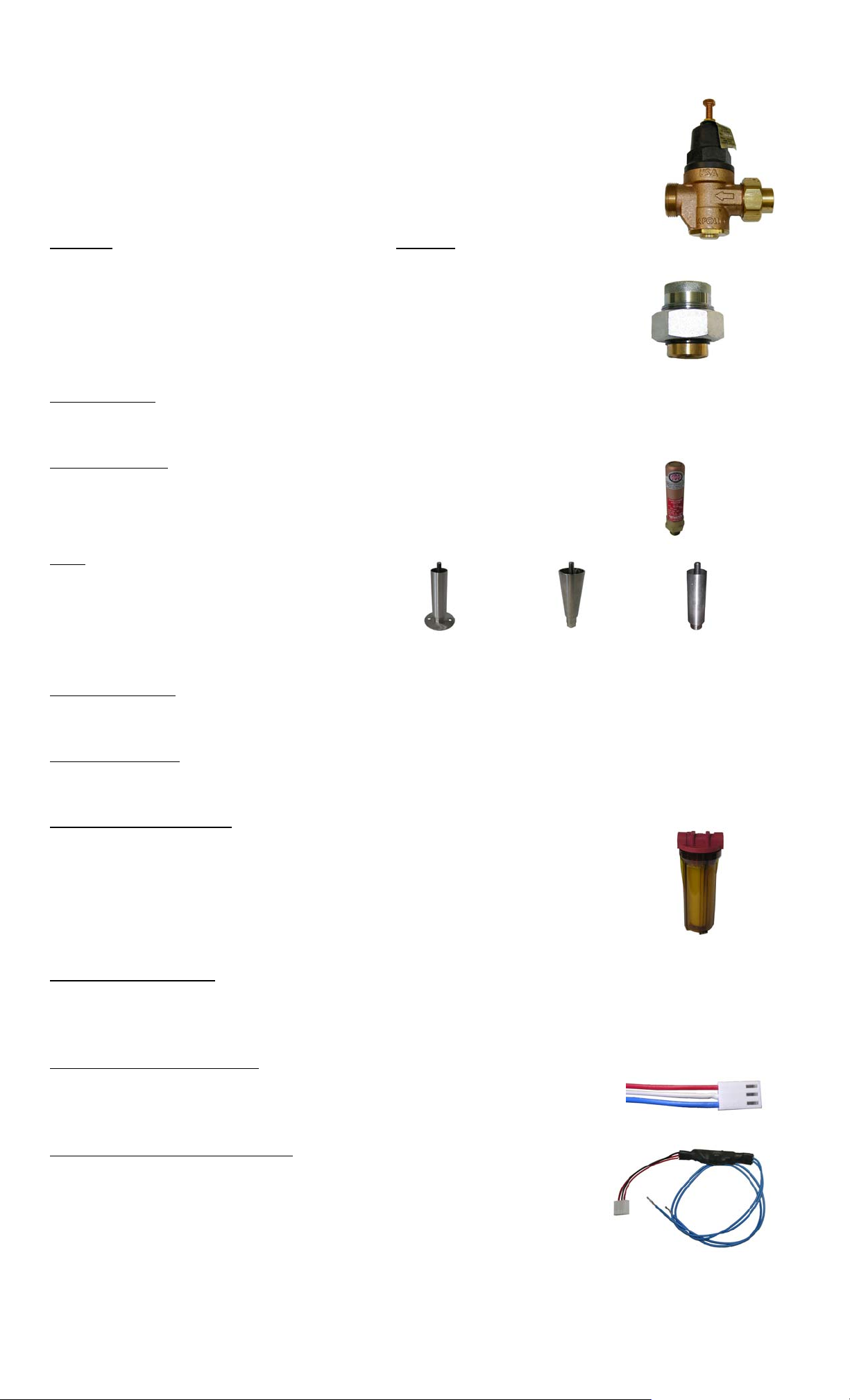
PRESSURE REDUCING VALVE
A bronze pressure reducing valve with built-in bypass is supplied with the unit.
This valve is shipped separately for in-line installation. The ¾” NPT valve is
adjustable from 25-psi to 75-psi (approximately 17-psi to 67-psi including
pressure drop through the valve). The inlet connection is supplied with a ¾”
union by sweat connection. The outlet connection is ¾” female NPT. The set
screw located at the top of the diaphragm adjusts the pressure, turn clockwise to
decrease the pressure and counter-clockwise to increase the pressure. Pressure
reducing valves for the J3 and J4 models are optional.
DIELECTRIC UNIONS
Dielectric unions are provided for the inlet and outlet nipples to isolate stray
ground currents to reduce the possibility of galvanic corrosion. (Optional on the
J3 and J4 Models).
OPTIONAL EQUIPMENT
Slide Brackets
Available for the J6 Model only, these brackets allow for mounting the booster heater under a
counter. See slide bracket diagram on page 9 for details.
Shock Absorber
The optional shock absorber can be installed between the booster and the
dishwasher to reduce the harmful pressures resulting from quick closing
dishwasher solenoid valves.
Legs
In lieu of the standard black plastic legs,
optional adjustable legs are available in
stainless steel, die-cast nickel plated, and
floor mount stainless steel. All optional legs
are adjustable height type. Floor Mount Nickel Plated Stainless Steel
Security Package
For prison and other secure facilities a tamper resistant package is available. All external screws are
spader type requiring a spader wrench for removal.
Alternate Voltage
Other voltages are available, including 277V single-phase, and 380V, 415V, and 440V three-phase.
Consult the factory for details.
Water Treatment System
The optional water treatment system provides superior mineral scale
prevention and corrosion control by feeding a special blend of scale
control compounds into the warm water stream before the heater. The inline system includes a clear cartridge housing to allow an operator to view
the cartridge and determine when it needs replacement without the need to
open the system.
XB1 Expansion Board
An optional expansion board to the control board can be used to for additional circuit firing when
more than two circuits are required and/or as an auxiliary high or low temperature alarm/relay. On
models with three contactors the XB1 is supplied as standard.
Remote Alarm Plug Adapter
An optional plug adapter is available to provide a remote fault alarm signal
through the J4 connector on the control board. See page 12 for installation
details.
24-Volt Heater Interlock Adapter
An optional plug adapter is available to interlock the heater via a 24-volt
signal through the J1 connector on the control board. The 24-volt heater
interlock adapter is supplied standard on the J3 model. See page 13 for
installation details. (Only available with r23 or later software).
8
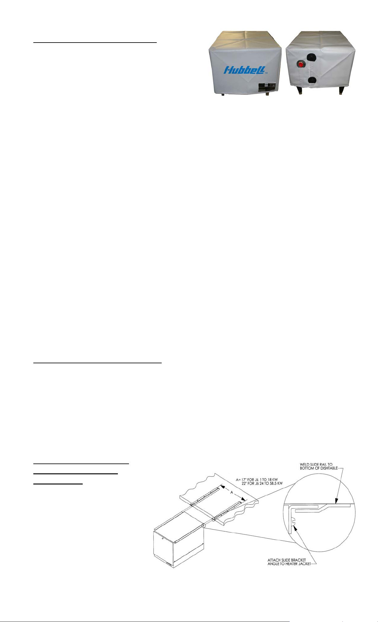
Protective Shrouds (J6 and J16 only)
An optional durable protective plastic shroud is
available to prevent damage to the booster due to
water intrusion. The cover fits snugly over the
entire booster and can be easily removed for
cleaning and service.
SECTION II – INSTALLATION AND START-UP
WARNING / CAUTION
• DO NOT TURN ON THE ELECTRIC POWER SUPPLY to this equipment until
heater is completely filled with water and all air has been released. If the heater is
NOT filled with water when the power is turned on, the heating elements will burn
out.
• For protection against excessive pressures and temperatures, local codes require the
installation of a temperature-and-pressure (T&P) relief valve certified by a nationally
recognized laboratory that maintains periodic inspection of production of listed
equipment of materials, as meeting the requirements for Relief Valves and Automatic
Gas Shutoff for Hot Water Supply Systems. ANSI Z21.22-1971. THE CUSTOMER
IS RESPONSIBLE TO PROTECT PROPERTY AND PERSONNEL FROM HARM
WHEN THE VALVE FUNCTIONS.
• All water heaters have a risk of leakage at some unpredictable time. IT IS THE
CUSTOMER'S RESPONSIBILITY TO PROVIDE A CATCH PAN OR OTHER
ADEQUATE MEANS, SO THAT THE RESULTANT FLOW OF WATER WILL
NOT DAMAGE FURNISHINGS OR PROPERTY.
• Installation or service of this unit requires ability equal to that of a licensed tradesman
in the field.
• The installation must conform to these instructions and any local authority having
jurisdiction. Grounding and electrical wiring connected to the unit must also conform
to the latest version of the National Electric Code NFPA-70.
WATER HEATER PLACEMENT
NOTE: For most effective operation, install the booster heater as close as possible to the
dishwasher. If the distance between the booster and the dishwasher exceeds NSF
requirements, recirculation methods must be employed.
1. Place the heater on a solid, level foundation in a clean, dry location as near as possible
to the dish washing machine.
2. The water heater should be protected from freezing and waterlines insulated to reduce
energy and water waste.
3. Leave a minimum of 18” clearance for element withdrawal and control access.
4. Do not install in an area where flammable liquids or combustible vapors are present.
SLIDE BRACKETS FOR
HANGING SUPPORT
MOUNTING
1. Weld slide rails to
bottom of dishtable.
Spacing should be 17”
for J6 models up to
18kW and 22” for J6
models 24 to 58.5kW.
J16 models are not
designed for use with
slide brackets.
9

2. Attach slide bracket angles to heater with #8 sheet metal screws. It will be necessary
to drill 1/8” holes into heater jacket for screw pilot holes.
3. Slide heater onto slide rails under dishtable.
PIPING INSTALLATION – See Diagrams
NOTES:
• No check valve may be installed in the supply line to the booster.
• All shut-off valves must be gate or ball valves – not globe valves.
• To minimize heat loss and maximize efficiency, hot water piping should be insulated.
• Teflon tape should be used on all NPT threaded pipe connections.
1. Install the factory supplied dielectric unions on the inlet and outlet piping.
2. Connect the cold/warm water inlet and hot water outlet to the appropriate connections
as shown; refer to the specifications for location and sizes.
IMPORTANT – Be certain to connect the outlet piping to the final rinse and not to the
wash tank. Insulate if over 3 feet.
IMPORTANT (applies to J6 Models only) – Do not turn the entering warm water or
exiting hot water nipples from their factory installed positions. The internal diffusers
are aligned at the factory and turning the nipple will change the diffuser position and
affect performance. Hubbell recommends that the inlet and outlet pipes are insulated
to prevent excessive heat loss.
IMPORTANT (applies to J6 Models only) – Do not apply heat directly to the entering
warm water or exiting hot water nipples. If sweat connections are to be used, sweat
tubing to the adapter before threading the adapter to the nipple on the heater. Any heat
applied to the heater nipple will damage the internal plastic diffuser and affect
performance.
3. Install the pressure reducing valve, when supplied, in the entering cold/warm water
inlet line and adjust to 20-psi. The set screw located at the top of the diaphragm adjusts
the pressure, turn clockwise to increase the pressure and counter-clockwise to decrease
the pressure. NOTE: Be sure to install the valve with flow in the proper direction as
indic a t e d b y t h e d i re c t i o n a l a r r o w on t h e v a lv e . IF A STANDARD PRESSURE
REGULATOR IS USED, it acts as a check valve and it is possible that thermal
expansion will cause the relief valve to drip or occasionally blow off a small amount
of water. To overcome this condition, it is recommended that a 3/8” by-pass
arrangement with a horizontal check valve be installed around the pressure regulator.
This will prevent annoyance caused by the relief valve dripping or blowing off.
NOTE: It is strongly recommended that a pressure reducing valve with built-in bypass
is installed in models where one is not supplied.
4. Install the combination temperature and pressure safety relief valve in the tapping
provided. Note that this is required by law for safety considerations.
Install into provided tapping Manual Release Lever
Temperature Probe
Outlet to floor drain
5. Install a relief valve overflow pipe to a nearby floor drain.
NOTE: Relief valve discharge piping limitations:
a. Termination to be plain end (no threads) and 6-inches above the drain.
b. Maximum 30-feet.
c. Maximum four (4) elbows.
d. No reduction in line size.
10
e. No valve of any type to be installed between the relief valve and tank or in the
drain line.
6. A shock absorber is recommended in the hot water outlet line to soften the water
hammer caused by automatic dishwasher solenoid valves.
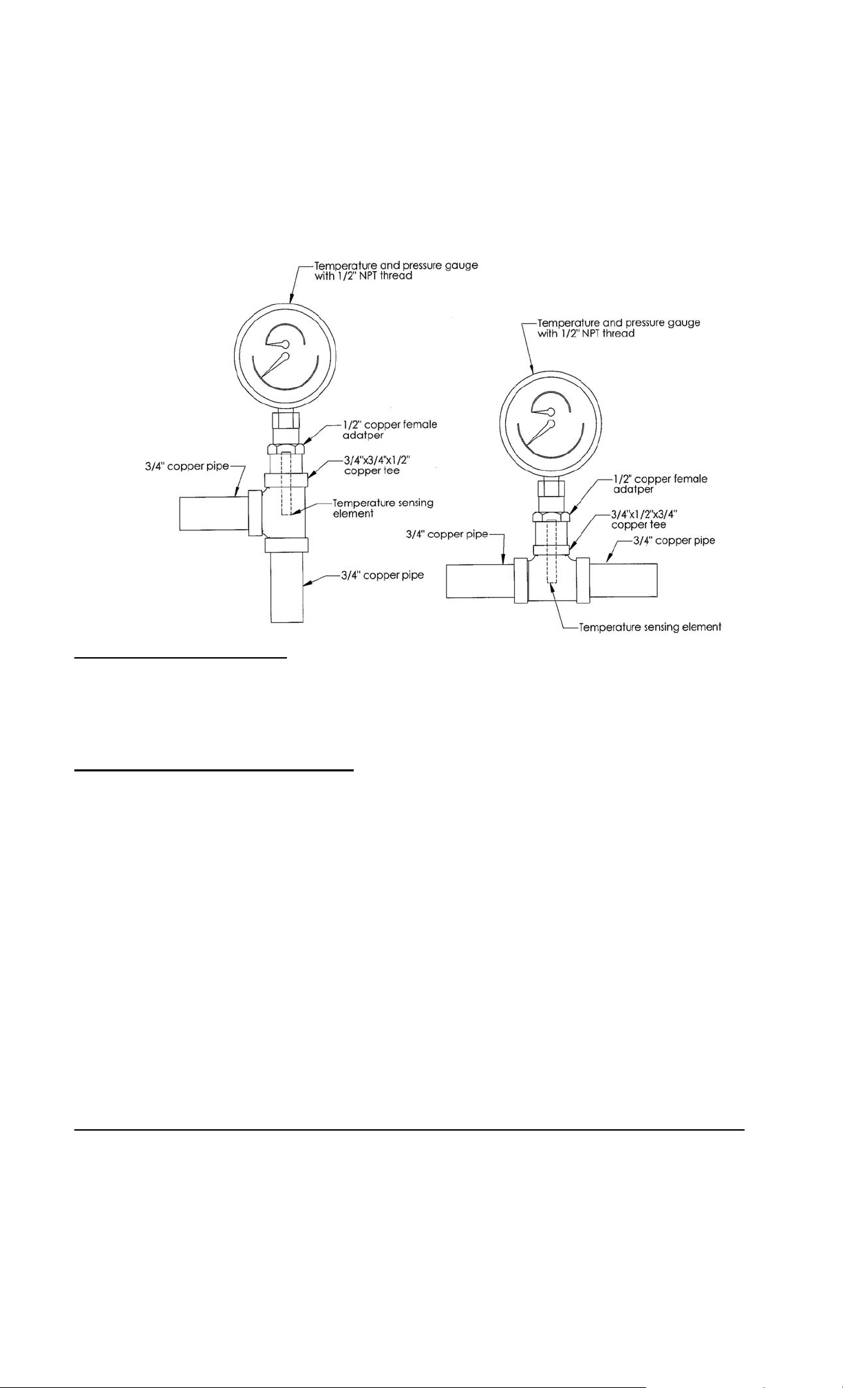
7. Install the in-line pressure and temperature gauge, when supplied, in the entering
cold/warm water line. If supplied, install the optional second dial temperature and
pressure gauge in the outlet line. The temperature sensing element must be in the hot
water stream and the gauge must be mounted upright.
FILLING THE HEATER
1. Open the valve to the cold/warm water inlet and allow the heater and piping system to
completely fill, as indicated by a steady flow of water through the dishwasher rinse
nozzles.
NOTE: Flush the tank at full flow for 10 minutes prior to putting into service.
ELECTRICAL INSTALLATION
1. Enter the base through the factory cut KO’s with properly sized feeder leads, See
Wiring Chart. Single-phase installations require two (2) leads. All Hubbell 3-phase
heaters are intended for use with a 3-wire delta system plus ground. No neutral is
required. For a 4-wire plus ground system, install 3 legs of power plus the ground and
terminate the neutral leg.
2. Install these power leads into the box lugs on the power distribution block or magnetic
contactor, as required.
3. Connect incoming ground wire to ground lug supplied.
4. Check for proper grounding. Check for AC millivolts (mV) between the ground
connection at the booster and the inlet piping past the dielectric union (on the building
side, not the booster side). There should be zero potential/millivolts (mV). If not
zero, then the piping should be re-grounded.
5. All other electrical connections are made at the factory; therefore, no other electrical
connections are necessary.
6. Check all connections, including factory connections, for tightness.
OPTIONAL XB1 EXPANSION BOARD (used for temperature alarm / interlock)
1. If desired, the XB1 can be used as an alarm relay or a temperature interlock at a
setpoint other than the water temperature setpoint on the booster heater.
2. If the XB1 is not factory installed, mount the XB1 to the control panel and connect the
XB1 to the T1000 control board with the factory supplied cable between JX4 on the
XB1 and J1 and J4 on the T1000 and connect the ground between JX6 on the XB1
and J8 on the T1000.
3. Make connections as required to the relay terminal block. When the temperature drops
below the XB1 setpoint the relay is open between Normally Open (NO) and Common
11

(C) and the LED will flash green. When the temperature is above the XB1 setpoint the
ying
relay is closed between NO and C and the LED will be solid green. Use NO and C for
low temperature interlock or high temperature alarm. Use Normally Closed (NC) and C
for low temperature alarm. A red LED indicates an error.
Note: Alarm Rating (resistive):
Max.: 5A @ 120VAC
5A @ 24VDC
(JX5 L1) Power Wire
(Common, White)
(JX5 L2)Power Wire
(Black)
(JX5) (4) Connections
for Additional Circuit
Firing
(JX2) Low Temp.
Relay Terminal Block
(JX6) Ground
(JX4) Connection to
T1000
(JX3) To be used as
T1000 J1 Connection
(JX1) To be used as
T1000 J4 Connection
LED
Note: Once the XB1 is connected to the T1000 control board, an additional menu option will
be available to set the low temperature setpoint. See Section III.
FOR REMOTE ON/OFF CONTROL
To remotely control the On / Off operation of
the heater, it is recommended that a DPST
switch or relay (by others) be used to break
both power legs (white and black wires)
connected to the top two terminals of the J5
connector on the control board. See diagram at
right.
Use a NC (Normally Closed) relay to turn the
booster ON when energizing the relay coil or
to turn the booster OFF when de-energizing
the relay coil.
Use a NO (Normally Open) relay to turn the booster OFF when energizing the relay coil or
to turn the booster ON when de-energizing the relay coil.
OPTIONAL REMOTE ALARM CONTACTS
1. If desired, the control board can be wired to a remote alarm to indicate a reset fault
condition. These fault conditions include over-temperature, no probe, and low water
(when the configuration is set to manual reset).
2. This alarm can be wired to the J4 connector on the control board as shown below. To
facilitate this installation, an optional adapter, Hubbell P/N PLUG ADAPTER J4, can
be purchased to provide wire connections.
J4 Connector
Note: Rating (resistive)
Max. Switching Power:
60W, 62.5VA
Max. Switching Voltage:
220VDC, 250VAC
Max. Switching Current: 2A
Max. Carr
Current: 3A
PLUG ADAPTER J4
(NO)
(NC)
Note: That when the XB1 expansion board is used, the J4 PLUG ADAPTER should plug
into the JX1 connection on the XB1.
12
 Loading...