

Hubbell Heaters B106, B108, B1010, B1012, B1015 Maintenance Manual
...
OPERATING AND MAINTENANCE MANUAL FOR
ELECTRIC BOOSTER HEATER
ELECTRIC HEATER COMPANY
BASE MODEL “ B ”

HUBBELL
ELECTRIC HEATER COMPANY
P.O. BOX 288
STRATFORD, CT 06615
PHONE: (203) 378-2659
FAX: (203) 378-3593
INTERNET: http://www.hubbellheaters.com/
-- IMPORTANT --
Always reference the full model number and serial number when calling the factory.
WARNING / CAUTION
1. Tank is to be completely filled with water and all air is to be vented before energizing.
2. Due to the rigors of transportation, all connections should be checked for tightness before heater
is placed in operation.
3. Safety relief valve must be installed in tapping provided.
4. The refractory material used in heating elements may absorb some moisture during transit,
periods of storage, or when subjected to a humid environment. This moisture absorption results
in a cold insulation resistance of less than twenty (20) megohms. If this heater has been
subjected to the above condition, each heating element must be checked for insulation
resistance before energizing. A low megohm condition can be corrected by removing the
terminal hardware and baking the element in an oven at 350°F -700°F for several hours or until
the proper megohm reading is obtained.
5. KEEP AWAY FROM LIVE ELECTRICAL CIRCUITS.
Do not perform any maintenance, make any adjustments, or replace any components inside the
control panel with the high voltage power supply turned on. Under certain circumstances,
dangerous potentials may exist even when the power supply is off. To avoid casualties, always
turn the power supply safety switch to off, turn the charge or ground the circuit before
performing any maintenance or adjustment procedure.
6. The unit is designed to operate at pressure not more than 150 psi.
7. Generalized instructions and procedures cannot anticipate all situations. For this reason, only
qualified installers should perform the installations. A qualified installer is a person who has
licensed training and a working knowledge of the applicable codes regulation, tools, equipment,
and methods necessary for safe installation of an electric resistance water heater. If questions
regarding installation arise, check your local plumbing and electrical inspectors for proper
procedures and codes. If you cannot obtain the required information, contact the company.
2

TABLE OF CONTENTS
SECTION TITLE PAGE #
I GENERAL DESCRIPTION AND CONSTRUCTION 5
II INSTALLATION 9
III SCHEDULED MAINTENANCE AND OPERATION 15
IV TROUBLESHOOTING 17
V SERVICING & REPLACEMENT OF PARTS 19
VI MISCELLANEOUS CHARTS AND FORMULAS 24
3

4
SECTION I - GENERAL DESCRIPTION AND CONSTRUCTION
GENERAL DESCRIPTION
This book describes a packaged electric booster heater that is typically used to provide 180°F sanitizing
rinse water. The complete assembly consists of the storage tank, immersion electric heating element(s),
thermostat, safety relief valve, safety high temperature cut out, magnetic contactor(s), and any other
required electrical operating control. Optional equipment may be supplied with your unit. Please
consult the product drawing for details specific to your assembly. The unit is factory assembled,
insulated, jacketed, wired, tested, and ready for electrical and plumbing service connections.
CONSTRUCTION
TANK
The storage tank is constructed of type 316L stainless steel for maximum tank longevity. The tank is
formed by all welded construction and is designed for a maximum allowable working pressure of 150
psi (300 psi TP).
TANK CONNECTIONS
The heater is supplied with separate connections for the cold/warm inlet and the hot water outlet. Water
entering the cold water inlet is deflected by means of a baffle within the tank. A ¾-inch FNPT
connection is provided for mounting a combination safety temperature and pressure relief valve. An
overflow line should be utilized from the relief valve outlet to a floor drain. See drawing for locations
and sizes.
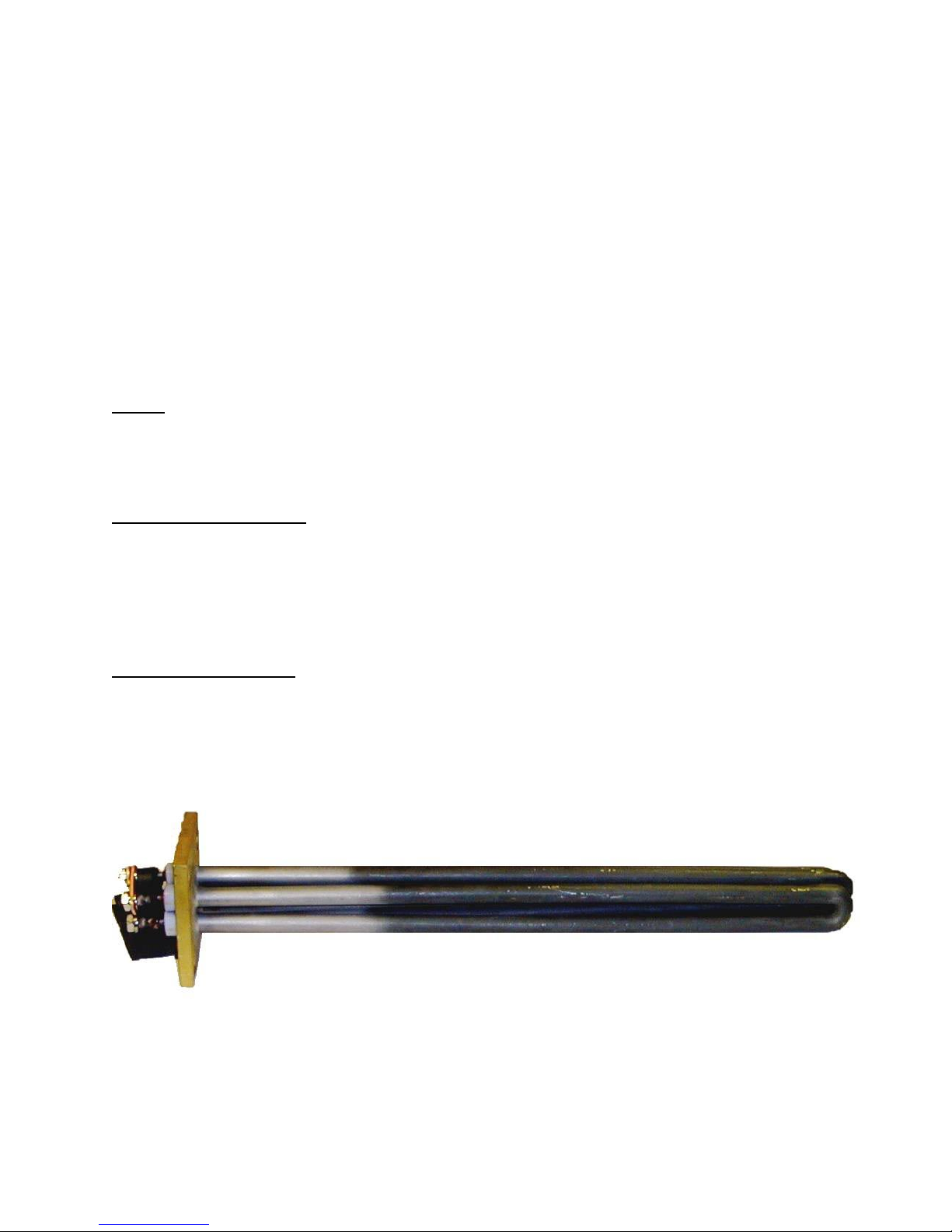
HEATING ELEMENT
The water heater is supplied with an electric immersion heating element assembly(s), composed of
incoloy or copper sheathed elements that are brazed into a brass flange. Each assembly is fastened to a
corresponding tank flange using a gasket and four (4) 3/8-16 x 1-inch long hex head steel bolts and
nuts. See drawing for voltage and power ratings.
5

CONTROL THERMOSTAT
The water heater is supplied with an immersion thermostatic switch
that is installed and wired at the factory. The thermostat can be adjusted
through a range of 100° - 195° F and is adjustable with a flat tip
screwdriver.
TEMPERATURE HIGH LIMIT SWITCH
A surface mounted high temperature cut-off switch with manual reset, factory set at 205° F is provided.
In the event of an over-temperature condition, the thermostat will disengage the operating coils in the
magnetic contactor(s). The high limit must be manually reset thereafter to restart the heater.
Manual Reset
MAGNETIC CONTACTOR
The magnetic contactor(s) is a heavy-duty resistive load type
rated for 100,000 cycles. The contactor supplies power to the
heating element(s) based on the resistive load (non-inductive) of
the heater only when the thermostatic switch is engaged, thereby
pulling in the contacts until the desired temperature is reached.
At this point, the contacts will drop out, which in turn
disconnects power from the elements.
OUTER SHELL , INSULATION, AND SUPPORTS
The tank is encapsulated in 2-inches of high-density fiberglass insulation. The protective shell is
constructed of galvaneel and is coated with a durable silver hammertone finish. Heavy gauge steel
support legs are provided.
6
OPTIONS
The following optional features may be included in your water heater. Reference included drawing
specific to your heater for further details.
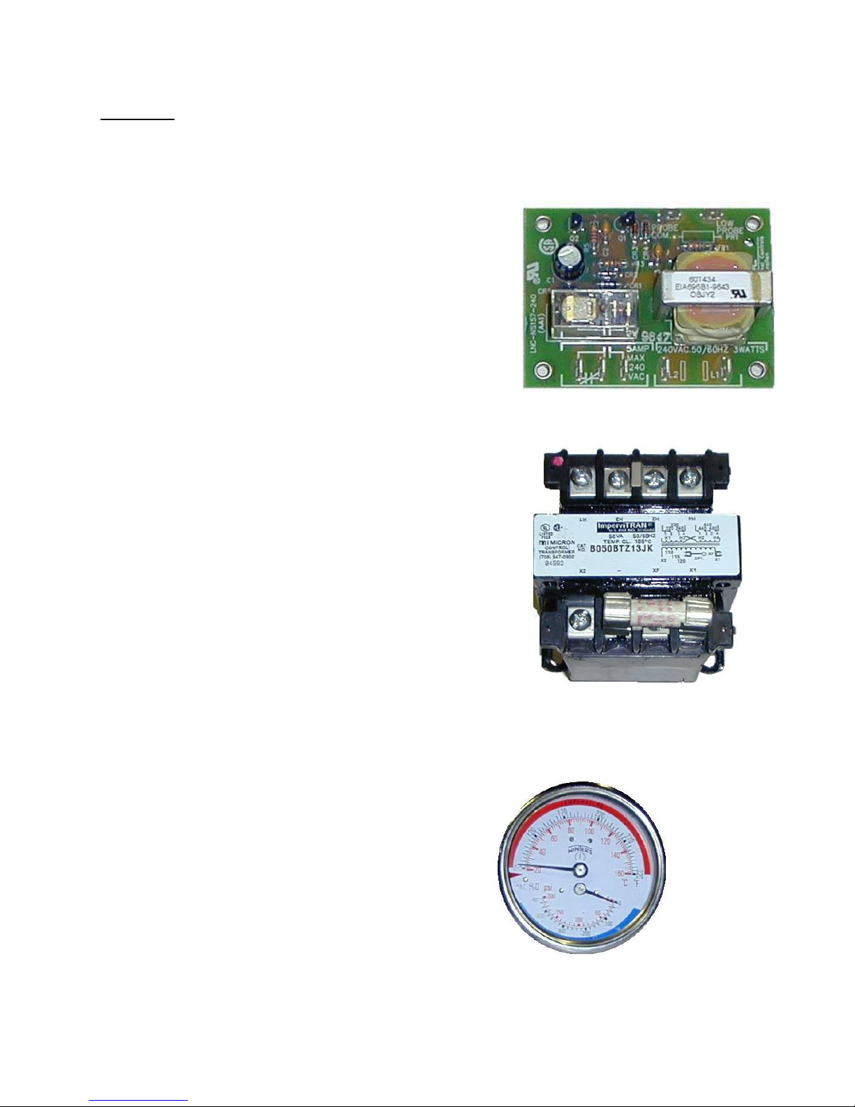
Low Water Cut-Off
Used as a safety device, the electronic low water cut-off is
used to detect a low water situation and disengage the
operating coils in the magnetic contactor(s). Once the
condition is remedied, the low water cut-off switch is
automatically reset.
Fused Low Voltage Transformer
A fused low voltage transformer may be supplied. This option
is used only in 480-volt systems with low water cut-offs to step
down the voltage to 240-volt for safety when working with
control circuits.
Dial Temperature and Pressure Gauge
A combination temperature (70° - 250° F) and pressure (0
– 200 psi) gauge with 2½-inch dial may be supplied for
in-line installation (shipped loose).
7
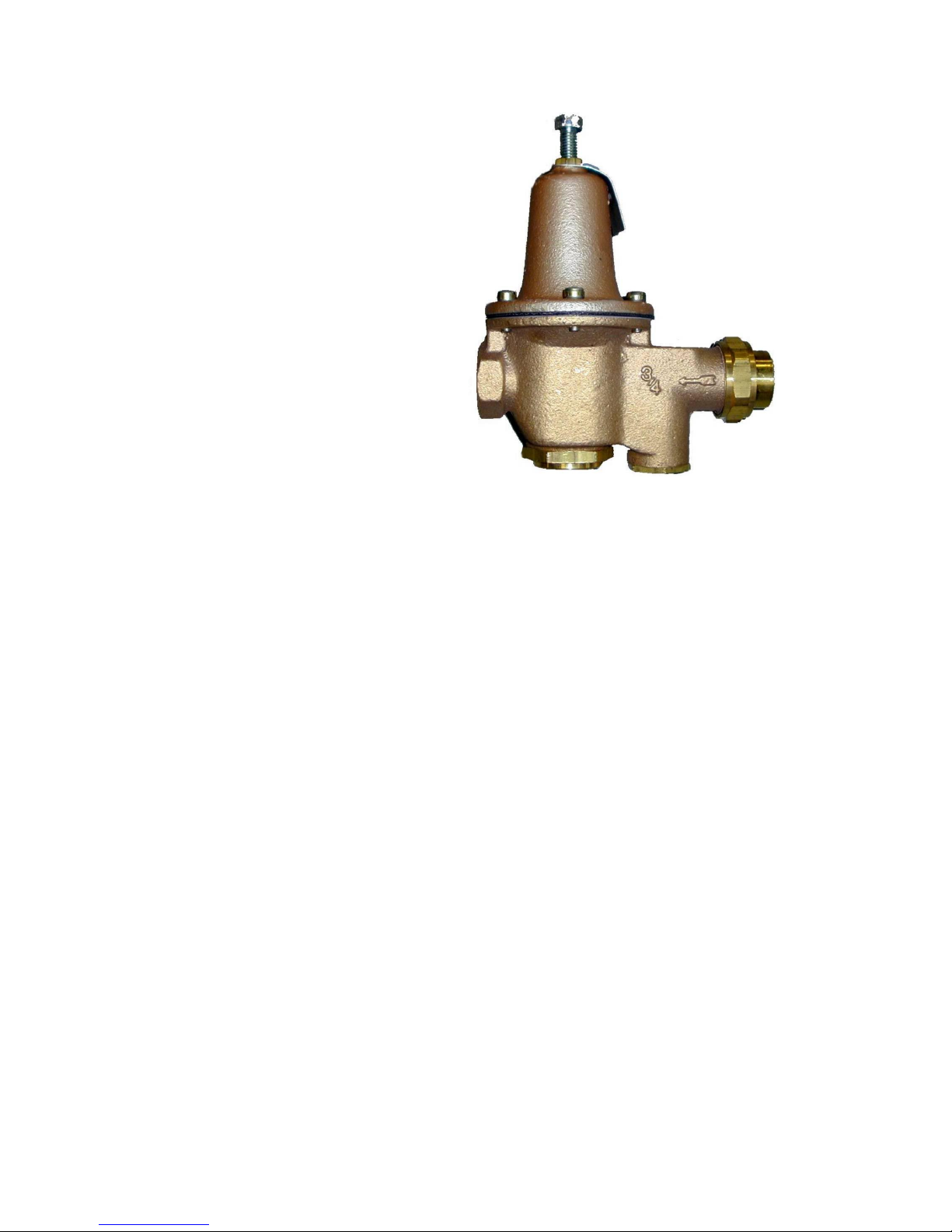
Pressure Reducing Valve
An optional pressure reducing valve with
built-in bypass may be supplied. This valve is
shipped separately for in-line installation.
Stainless Steel Outer Jacket
An optional stainless steel outer jacket may replace the standard galvaneel jacket.
Suspension Straps
For under counter, off the floor operation an optional suspension strap may be supplied in place of the
standard support legs.
8
 Loading...