

Hubbell Heaters 280-3, 220-3, 180-2, 240-3, 145-2 Installation, Operation And Maintenance Manual
...
INSTALLATION, OPERATION, AND
MAINTENANCE MANUAL FOR
THE HUBBELL TANKLESS WATER HEATER
ELECTRIC HEATER COMPANY
Edition 2016A

2
HUBBELL
ELECTRIC HEATER COMPANY
P.O. BOX 288
STRATFORD, CT 06615-0288
PHONE: (877) 649-8589
FAX: (203) 378-3593
INTERNET: http://www.buytankless.com
Important Safety Information
1. You must read and follow all instructions. Serious bodily injury or death could occur
if you ignore this warning.
2. All circuit breakers and/or disconnect switches servicing the heater must be turned off
when installing, uninstalling, or repairing this water heater.
3. The Hubbell Tankless Water Heater must be grounded.
4. The unit must be installed by a licensed electrician and plumber.
5. The unit must be wired in accordance with the current version of the National
Electrical Code (US) or Canadian Electric Code (Canada).
6. This installation must comply with all national, state, and local plumbing and
electrical codes.
7. When the heater is not within sight of the electrical circuit breakers, an additional
local means of disconnection of all ungrounded conductors must be provided that is
within sight of the appliance or a circuit breaker lockout must be used. (Ref. NEC
422.31)
8. If the Hubbell Tankless Water Heater is installed in a location where water damage
could occur in the event of a leak, it is recommended that a drip pan be installed and
connected to a suitable drain. Alternatively, an active water leak detector and shut off
valve can be installed to turn off your water supply in the event a leak is detected.
9. If water supply has a high mineral content, a water softening system is recommended.
Damage to the water heater resulting from scale or hard minerals will not be covered
under warranty.
10. When the heater is installed in a well water system or if the plumbing system is prone
to introducing air into the heater, it is highly recommended that an air separator be
installed in the cold water feed to the heater to avoid possible failure of the heating
element and/or heating chamber.

3
TABLE OF CONTENTS
SECTION
TITLE
PAGE No.
I
TANKLESS WATER HEATER OPERATING PRINCIPLE
4
II
GENERAL DESCRIPTION AND CONSTRUCTION
5
III
INSTALLATION
10
IV
OPERATION AND MAINTENANCE
15
V
TROUBLESHOOTING
21
VI
SERVICING & REPLACEMENT OF PARTS
27
VII
PARTS LIST
32
VIII
WARRANTY
33
APP. I
SUB-PANEL WIRING DETAILS
36

4
SECTION I – TANKLESS WATER HEATER OPERATING PRINCIPLE
How the Hubbell Tankless Water Heater Works:
For the most part, operating your new tankless water heater is very similar to using any
traditional water heater system. However, it is very important that you carefully read all of
the set-up procedures and operating instructions to ensure maximum performance and
energy savings from your new water heater.
Your Hubbell Tankless Water Heater does not store hot water like a conventional tank-type
water heater. It contains high powered heating elements that are capable of heating water
instantly on-demand as you need it. As soon as you turn on a hot water faucet, a
sophisticated flow sensor within the heater recognizes that you have turned on the water.
This sensor measures the water flow rate while two other sensors measure the incoming and
outgoing water temperature. This information is transmitted continually to the
microprocessor controller which determines the precise amount of power to send to the
heating elements to heat the water to your desired temperature. The Hubbell tankless water
heater only uses as much power as is needed to meet the demand by fully modulating the
heating elements from 0 to 100%. Since your new water heater works on a demand basis, it
will absolutely never run out of hot water no matter how many back to back showers you
run!
It is important to keep in mind that every tankless water heater has a maximum flow rate. If
you exceed this flow rate, the heater will not be capable of fully heating water. How much
hot water your heater can provide will depend on the model you have selected and your
incoming water temperature. If you live in an area of the country where inlet cold water
temperature average 55° F or you have cold winters, you will probably NOT be able to run
multiple large water demand fixtures at the same time. However, you will be able to run all
your hot water fixtures back to back without ever having to wait. You will enjoy
UNLIMITED HOT WATER. See the charts in Section II to determine the maximum flow
rates.
Moreover, since a tankless water heater eliminates the ongoing thermal losses caused by
storing hot water in a tank, you will enjoy significant energy savings over a conventional
tank type water heater.
When you use hot water from a conventional tank type water heater, you need to mix a
considerable volume of cold water to cool the hot water down to a safe, comfortable level.
You need to do this because the heater is set at an extremely high temperature to prevent it
from running out of hot water quickly. With a tankless water heater, you typically set the
temperature at a much lower level since it is capable of heating your water on demand. This
level will be much closer to the actual temperature at which you feel comfortable showering
or bathing. As such, you will no longer need to mix much cold water to run a shower or
bath; in fact, you may mix very little or no cold water. This is perfectly normal and means
that you are no longer wasting energy by overheating your water.
5
SECTION II – GENERAL DESCRIPTION AND CONSTRUCTION
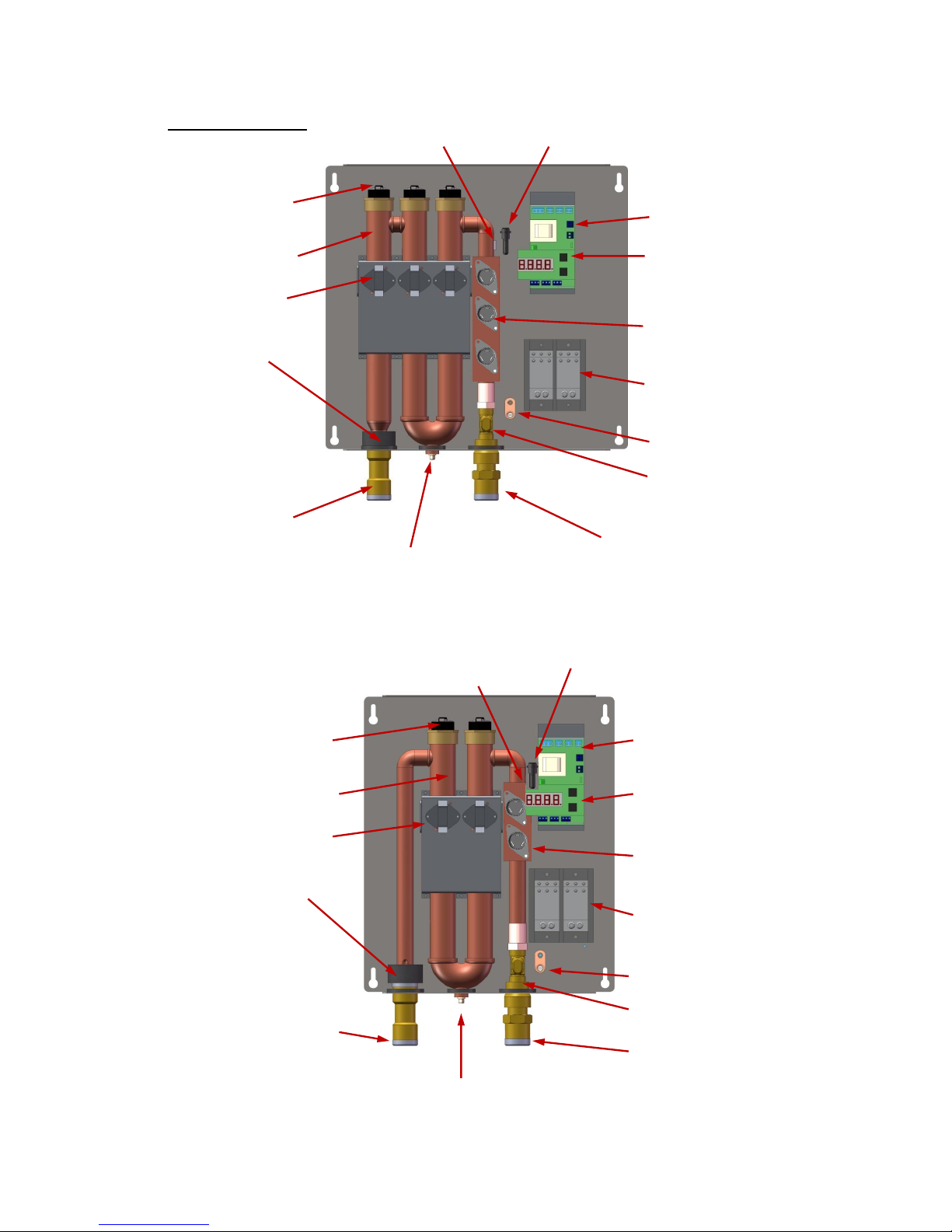
Product Overview:
Inlet Temp. Sensor Control Fuse
Heating Element Temperature
Controller
Heating Chamber LED Digital Display
(with buttons)
Hi-Limit Switch
Element Switching
Device (Triac)
Outlet Temp.
Sensor Power Distribution
Block
Ground Lug
Flow Meter
Hot Water Outlet
Cold Water Inlet
Drain
3-Element Design (Models 280-3, 240-3, and 220-3)
Control Fuse
Heating Element Temperature
Controller
Heating Chamber LED Digital Display
(with buttons)
Hi-Limit Switch
Element Switching
Device (Triac)
Outlet Temp.
Sensor Power Distribution
Block
Ground Lug
Flow Meter
Hot Water Outlet
Cold Water Inlet
Drain
2-Element Design (Models 180-2, 165-2, 145-2, and 110-2)
Inlet Temp. Sensor

6
Hubbell Tankless Water Heater Selection Overview:
40°F 45°F 50°F 55°F 60°F 65°F 70°F 75°F
280-3
27 112.5 200 2.8 3.1 3.4 3.7 4.1 4.6 5.3 6.2
240-3
24 100.0 200 2.5 2.7 3 3.3 3.6 4.1 4.7 5.5
220-3
21 87.5 200 2.2 2.4 2.6 2.9 3.2 3.6 4.1 4.8
180-2
18 75.0 150 1.9 2.1 2.2 2.5 2.7 3.1 3.5 4.1
165-2
16 66.7 125 1.7 1.8 2 2.2 2.4 2.7 3.1 3.6
145-2
14 58.3 100 1.5 1.6 1.7 1.9 2.1 2.4 2.7 3.2
110-2 11 45.8 100 1.2 1.3 1.4 1.5 1.7 1.9 2.1 2.5
Model
No.
kW
Amps @
240V
Min. Required
Home Service
(Amps)
Max. flow (GPM) of water heated to 105°F with
incoming cold water temperature of
Note: Recovery rates (GPM) are based upon an actual supply voltage of 240 volts with no
voltage drop. If the actual supply voltage is less than 240 volts, the recovery rating (GPM) will
be reduced. Please see the wattage de-rating and flow rate formulas at the end of Section II to
determine the actual power (kW) and recovery rate (GPM) when voltage is less than 240 volts.
Tankless Pressure Drop Chart:
Technical Specifications Common to All Models:
Materials:
Copper Exchanger /
Stainless Steel Casing
Plumbing
Connection:
¾” Copper, CPVC,
or PEX
Voltage:
208-240 Volts / 1 Ph
Operating Range:
5 – 150 psi
Frequency:
50 / 60 Hz
Protection:
Thermal Auto Reset
Energy Efficiency:
98%
0
2
4
6
8
10
12
14
16
0 1 2 3 4 5 6 7 8
2-Element
3-Element
GPM
Pressure Drop (psi)

7
Model 280-3
Our most powerful residential electric tankless water
heater. This 27 kW water heater is configured for
cold climates where the incoming water temperature
can drop below 45° F. The Model 280-3 is well suited
for homes in the northern U.S. and Canada, and those
in the southern U.S. that have large Roman-style or
Jacuzzi tubs and that have generally more demanding
water usage needs.
Technical Specifications:
Dimensions:
17” x 16.2” x 3.6”
Customer Double-Pole
Circuit Breaker / Fused
Disconnect Required:
1 x 125A or
2 x 60A or
3 x 40A
Weight:
20 lbs.
kW / Elements:
27 kW / 3 elements
Max. Amps:
112.5 A @ 240 V
Model 240-3
The 24 kW water heater is configured for climates
where incoming water temperatures are in the 50° 70° F range. The Model 240-3 is suitable as a whole
house water heater.
Technical Specifications:
Dimensions:
17” x 16.2” x 3.6”
Customer Double-Pole
Circuit Breaker / Fused
Disconnect Required:
1 x 110A or
2 x 60A or
3 x 40A
Weight:
20 lbs.
kW / Elements:
24 kW / 3 elements
Max. Amps:
100 A @ 240 V
Model 220-3
The 21 kW, water heater is configured for cold
climates where the incoming water temperature can
drop below 55° F. The Model 220-3 is well suited
for homes in the northern U.S. and Canada, and
those in the southern U.S. that have large Romanstyle or Jacuzzi tubs and that have generally more
demanding water usage needs.
Technical Specifications:
Dimensions:
17” x 16.2” x 3.6”
Max. Amps:
87.5 A @ 240 V
Weight:
20 lbs.
Customer Double-Pole
Circuit Breaker Required:
1 x 100A or
2 x 50A
kW / Elements:
21 kW / 3 elements
100 105 110 115 120 125
40 3.1 2.8 2.6 2.5 2.3 2.2
45 3.4 3.1 2.8 2.6 2.5 2.3
50 3.7 3.4 3.1 2.8 2.6 2.5
55 4.1 3.7 3.4 3.1 2.8 2.6
60 4.6 4.1 3.7 3.4 3.1 2.8
65 5.3 4.6 4.1 3.7 3.4 3.1
70 6.2 5.3 4.6 4.1 3.7 3.4
75 7.4 6.2 5.3 4.6 4.1 3.7
Outlet Temp. (°F)
Maximum Flow Rate (GPM)
Inlet
Temp.
(°F)
100 105 110 115 120 125
40 2.7 2.5 2.3 2.2 2.1 1.9
45 3 2.7 2.5 2.3 2.2 2.1
50 3.3 3 2.7 2.5 2.3 2.2
55 3.6 3.3 3 2.7 2.5 2.3
60 4.1 3.6 3.3 3 2.7 2.5
65 4.7 4.1 3.6 3.3 3 2.7
70 5.5 4.7 4.1 3.6 3.3 3
75 6.6 5.5 4.7 4.1 3.6 3.3
Outlet Temp. (°F)
Maximum Flow Rate (GPM)
Inlet
Temp.
(°F)
100 105 110 115 120 125
40 2.5 2.3 2.1 2 1.9 1.8
45 2.7 2.5 2.3 2.1 2 1.9
50 3 2.7 2.5 2.3 2.1 2
55 3.3 3 2.7 2.5 2.3 2.1
60 3.8 3.3 3 2.7 2.5 2.3
65 4.3 3.8 3.3 3 2.7 2.5
70 5 4.3 3.8 3.3 3 2.7
75 6 5 4.3 3.8 3.3 3
Outlet Temp. (°F)
Maximum Flow Rate (GPM)
Inlet
Temp.
(°F)

8
Model 180-2
The 18 kW water heater is configured for climates
where incoming water temperatures are in the
60° -70° F range. The Model 180-2 is suitable as a
whole house water heater.
Technical Specifications:
Dimensions:
13.5” x 16.2” x 3.6”
Max. Amps:
75 A @ 240 V
Weight:
16 lbs.
Customer Double-Pole
Circuit Breaker Required:
1 x 80A or
2 x 40A
kW / Elements:
18 kW / 2 elements
Model 165-2
The 16 kW Model 165-2 is designed for moderate
climates where the coldest incoming water
temperature is 60° F or greater. As a whole house
model, the Model 165-2 is best suited to homes in the
southernmost regions of the U.S. (i.e. Southern
California, Texas, Florida, etc.), as well as Mexico
and the Caribbean.
Technical Specifications:
Dimensions:
13.5” x 16.2” x 3.6”
Max. Amps:
67 A @ 240 V
Weight:
16 lbs.
Customer Double-Pole
Circuit Breaker Required:
1 x 80A or
2 x 40A
kW / Elements:
16 kW / 2 elements
Model 145-2
The 14 kW Model 145-2 tankless water heater is
configured for climates where the lowest incoming
water temperature is above 70° F. The Model 145-2
is used primarily in warm climates as a whole house
unit in tropical climates.
Technical Specifications:
Dimensions:
13.5” x 16.2” x 3.6”
Max. Amps:
59 A @ 240 V
Weight:
16 lbs.
Customer Double-Pole
Circuit Breaker Required:
1 x 70A or
2 x 35A
kW / Elements:
14 kW / 2 elements
100 105 110 115 120 125
40 2.1 1.9 1.8 1.6 1.5 1.4
45 2.2 2.1 1.9 1.8 1.6 1.5
50 2.5 2.2 2.1 1.9 1.8 1.6
55 2.7 2.5 2.2 2.1 1.9 1.8
60 3.1 2.7 2.5 2.2 2.1 1.9
65 3.5 3.1 2.7 2.5 2.2 2.1
70 4.1 3.5 3.1 2.7 2.5 2.2
75 4.9 4.1 3.5 3.1 2.7 2.5
Outlet Temp. (°F)
Maximum Flow Rate (GPM)
Inlet
Temp.
(°F)
100 105 110 115 120 125
40 1.8 1.7 1.6 1.5 1.4 1.3
45 2 1.8 1.7 1.6 1.5 1.4
50 2.2 2 1.8 1.7 1.6 1.5
55 2.4 2.2 2 1.8 1.7 1.6
60 2.7 2.4 2.2 2 1.8 1.7
65 3.1 2.7 2.4 2.2 2 1.8
70 3.6 3.1 2.7 2.4 2.2 2
75 4.4 3.6 3.1 2.7 2.4 2.2
Outlet Temp. (°F)
Maximum Flow Rate (GPM)
Inlet
Temp.
(°F)
100 105 110 115 120 125
40 1.6 1.5 1.4 1.3 1.2 1.1
45 1.7 1.6 1.5 1.4 1.3 1.2
50 1.9 1.7 1.6 1.5 1.4 1.3
55 2.1 1.9 1.7 1.6 1.5 1.4
60 2.4 2.1 1.9 1.7 1.6 1.5
65 2.7 2.4 2.1 1.9 1.7 1.6
70 3.2 2.7 2.4 2.1 1.9 1.7
75 3.8 3.2 2.7 2.4 2.1 1.9
Outlet Temp. (°F)
Maximum Flow Rate (GPM)
Inlet
Temp.
(°F)

9
Model 110-2
The 11 kW Model 110-2 tankless water heater is
designed for moderate climates where the lowest
incoming water temperature is above 70° F. The
Model 110-2 is a point of use or booster model in
warm climates as opposed to a whole house water
heater.
Technical Specifications:
Dimensions:
13.5” x 16.2” x 3.6”
Max. Amps:
46 A @ 240 V
Weight:
16 lbs.
Customer Double-Pole
Circuit Breaker Required:
1 x 50A or
2 x 25A
kW / Elements:
11 kW / 2 elements
Alternate Voltage Table
The tables below lists the power in kW and the amperages for each model when connected
to voltages other than 240 volts.
Wattage De-rating Formula:
Applied Voltage2
× Rated Wattage = Actual Wattage
Rated Voltage2
For example: If installing a 27 kW unit, Model 280-3, when actual voltage is 212 V,
2122
=
44,944
= 0.78 × 27,000 W = 21,060 W @ 212 V
2402
57,600
Amperage Formula:
Watts
=Amps (Single Phase)
Volts
Flow Rate Formulas:
To determine power (kW) requirement
____GPM × ____ °F T × 0.1465 = ____ kW
To determine temperature rise
____ kW × 6.824 ÷ ____ GPM = ____°F T
To determine flow rate
____ kW × 6.824 ÷ ____ °FT = ____ GPM
100 105 110 115 120 125
40 1.3 1.2 1.1 1 0.9 0.9
45 1.4 1.3 1.2 1.1 1 0.9
50 1.5 1.4 1.3 1.2 1.1 1
55 1.7 1.5 1.4 1.3 1.2 1.1
60 1.9 1.7 1.5 1.4 1.3 1.2
65 2.1 1.9 1.7 1.5 1.4 1.3
70 2.5 2.1 1.9 1.7 1.5 1.4
75 3 2.5 2.1 1.9 1.7 1.5
Outlet Temp. (°F)
Maximum Flow Rate (GPM)
Inlet
Temp.
(°F)
208 220 230
280-3 20.28 22.69 24.80
240-3 18.03 20.17 22.04
220-3 15.77 17.65 19.29
180-2 13.52 15.13 16.53
165-2 12.02 13.44 14.69
145-2 10.52 11.76 12.86
110-2 8.26 9.24 10.10
Connected Voltage
Power (kW)
Model
No.
208 220 230
280-3 97.50 103.13 107.81
240-3 86.67 91.67 95.83
220-3 75.83 80.21 83.85
180-2 65.00 68.75 71.88
165-2 57.78 61.11 63.89
145-2 50.56 53.47 55.90
110-2 39.72 42.01 43.92
Connected Voltage
Amperage
Model
No.

10
SECTION III – INSTALLATION
WARNING: Serious bodily injury or death may occur if the following warnings are
ignored.
All circuit breakers and/or disconnect switches servicing this heater must be turned
off before installing, repairing or uninstalling this water heater.
Installation of this product is restricted to indoor locations.
Installation
MUST
be done by a licensed electrician and licensed plumber.
Locating and Mounting Instructions:
Your tankless water heater can be installed just about anywhere! Due to the small size of
your water heater, it can be mounted in many small spaces, including closets, under sinks, in
pantries, or under stair storage areas. However, there are some important guidelines to
follow that will ensure that your installation is both safe and convenient in the event that
future servicing is required.
This product is designed to be installed indoors only. You may be able to install your unit in
an outdoor location as long as it is mounted in a suitable enclosure that protects it from rain,
splashed water, direct sunlight, debris and insects. This product should NOT be installed in a
location where it may be subjected to freezing temperatures. If the water inside your tankless
water heater freezes, it can cause severe and permanent damage that is not covered under
your warranty. If you suspect that your tankless water heater may have frozen, do not turn
on the heater until it has thawed and you have inspected the system for leaks.
When selecting an installation location, give consideration to your existing plumbing
configuration, location of your main electrical panel, and location of your bathroom, kitchen
and laundry area. Try to choose a location that does not require you to make major
plumbing alterations, that is close to your main electrical panel (this will reduce the amount
of wire that you need to install), and that is physically close to the hot water fixtures that you
use most often. By locating the heater close to the points-of-use, you will reduce the amount
of time it takes for the hot water to travel from the water heater to your faucet. You should
also give consideration to future servicing. Do NOT locate the water heater in a location
that is difficult to access. In most cases, installing your tankless water heater in the same
location as your old conventional tank-type water heater will make the most sense.
You should avoid installing your tankless water heater in a location prone to excessive
humidity, moisture, or dust, or in an area where it may be splashed with water or other
liquids. Do NOT install under water pipes or air conditioning lines that might leak or
condense moisture that could then drip onto the heater. Do NOT install above electrical
boxes or junctions.
If you plan to install your water heater on a second floor or in a heated attic space, make sure
that you follow all code requirements for such installations as required for your area. We
recommend that you install a drip pan (connected to a drain) below the water heater to avoid
property damage in the unlikely event of a leak. Alternatively, you can install an active
water leak detector and shut-off valve designed to turn off your water supply in the event
that a leak is ever detected.
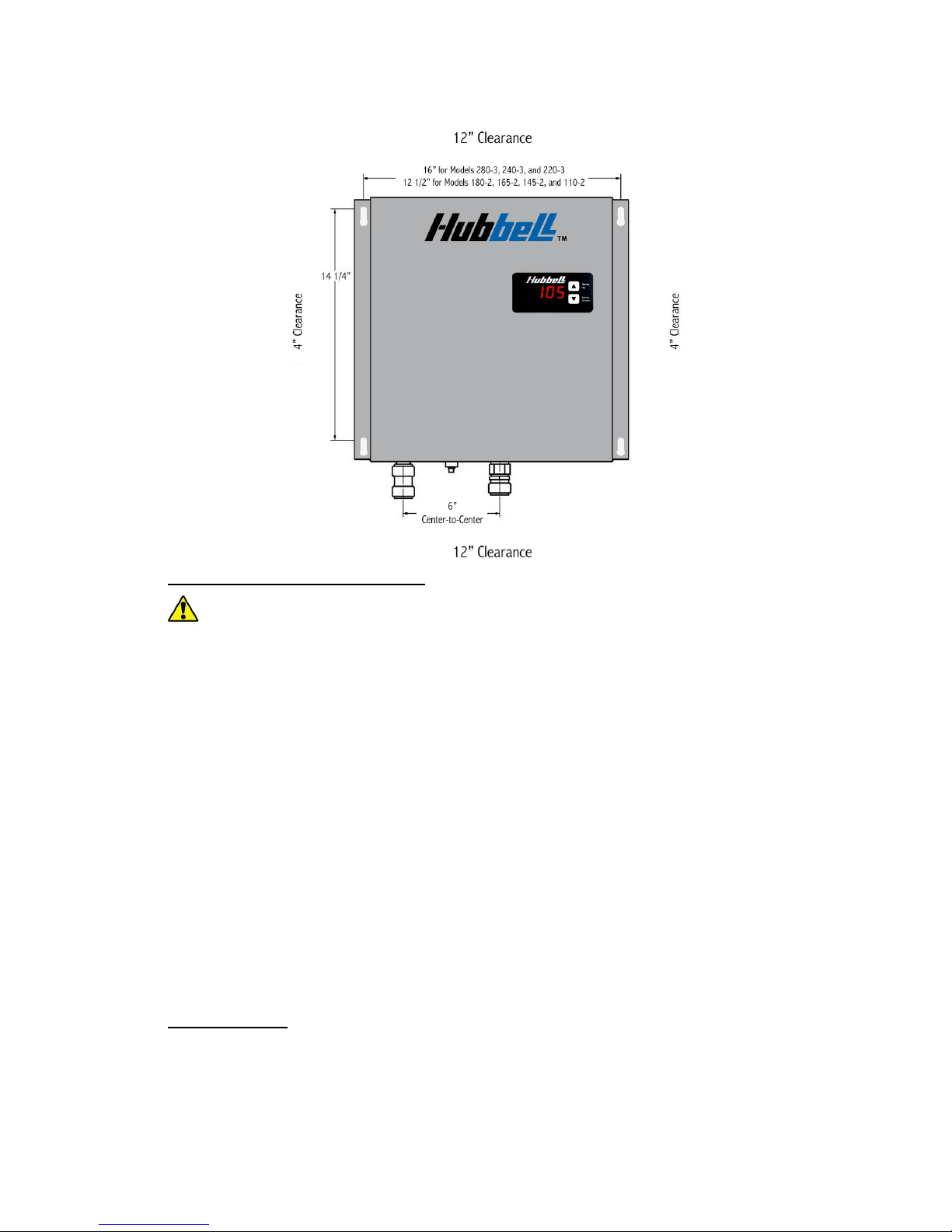
Mounting the unit:
Leave a minimum of 4” to both sides and 12” on the top and bottom of the unit.
Mount the water heater securely to the wall by putting four (4) screws through the
mounting holes.
11
Install a ¼” diameter bead of sealing caulk around the entire perimeter of the heater
between the heater back panel and the wall. This prevents any moisture or debris
from accumulating.
Plumbing Installation Instructions:
IMPORTANT INFORMATION:
Ensure all fitting installations comply with local plumbing and building codes.
This water heater does not require a temperature and pressure (T&P) relief valve.
You may install a T&P relief valve if the county, city or state plumbing code requires
it.
Installations in the Commonwealth of MASSACHUSETTS and KENTUCKY require
a
T&P
relief valve.
When connecting to a plumbing system that utilizes Flex or PVC, a
T&P
relief valve
should be used as added safety.
Do not connect the unit directly to CPVC pipe. You must use at least three feet of
copper pipe prior to connecting to any CPVC connection.
WARNING:
Do not solder any pipes with the unit connected to the pipes. Doing so
will damage the flow meter and void your warranty.
Before energizing the heater, run water for a minimum of three (3) minutes and
verify that all air has been removed.
Installation of an air separator device is recommended for installations where air can
be easily introduced into the water system (i.e. Well water systems, lake pumps, and
other municipal systems).
A shut off valve MUST be installed on inlet side of unit. A shut off valve on the
outlet is recommended.
Pipe Preparation:
Cut the tube so that the ends are square. WARNING: Ensure that there are no burrs or
damage to the cut end. This will prevent any damage to the internal o-ring.
Once the tubing end is cut square and clean, mark the pipe to be installed at a distance
of 1 ¾” from the end of the pipe. This is the insertion depth.
Check that fittings and tubing are clean, in good condition and are free from damage
and foreign objects.
12
Flushing the Line:
Before connecting the copper pipe to the water heater, it is extremely important to
flush the lines to eliminate all plumbing paste, residue, or debris in the lines.
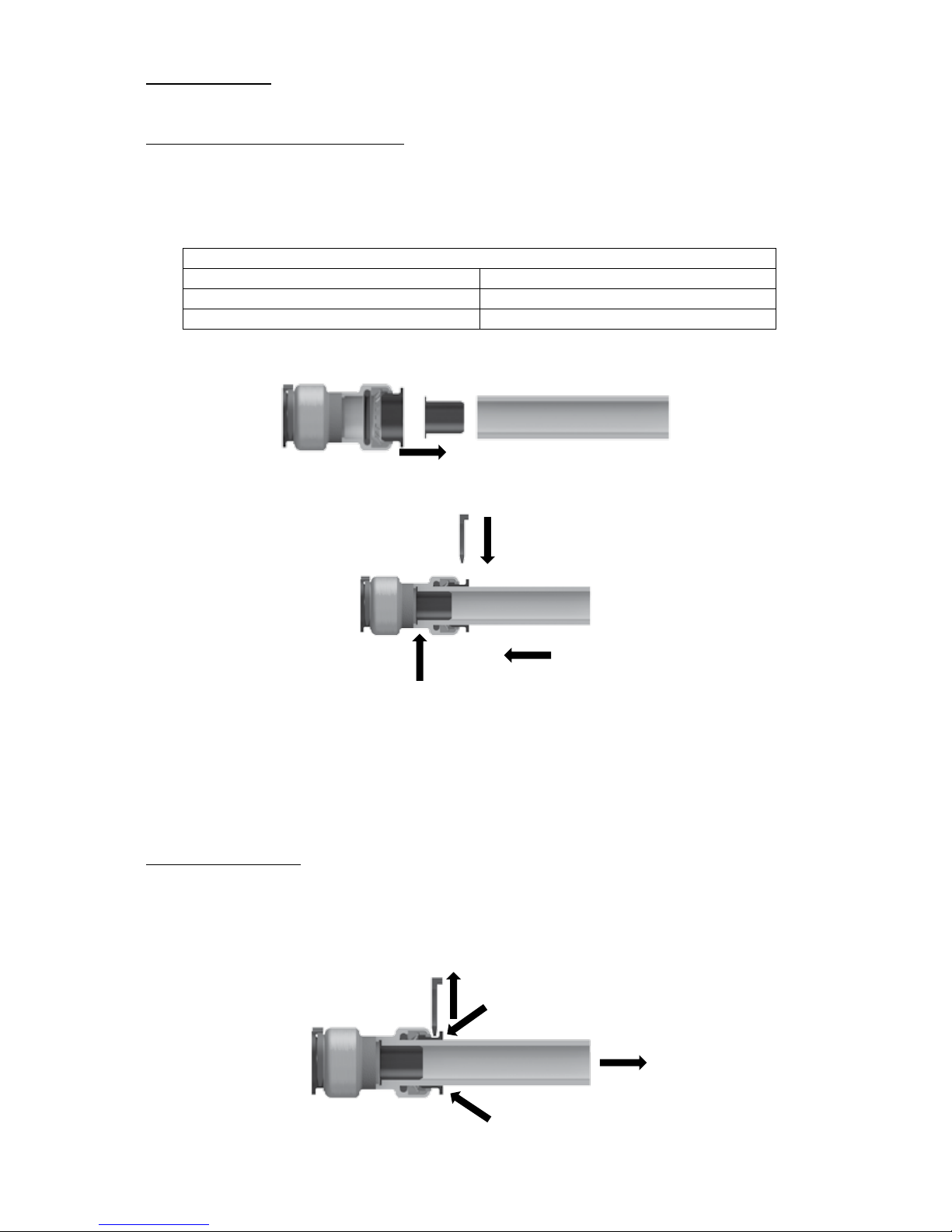
Installation to Quick-Connect Fitting:
Cut the pipe or tubing squarely and inspect the outside diameter of the pipe or tubing
to be sure there is no damage, nicks, burrs, or debris.
Deburr and clean pipe or tubing as necessary.
Use the insertion depth specified in the table below.
Insertion Depth Guide
Size
Insertion Depth
¾” CTS
1 1/8”
1” CTS
1 ¼”
If using PEX tubing, insert the supplied stiffener into the end of the pipe.
Make certain to push the tubing completely into the fitting until it comes into contact
with the internal tube stop.
Insert push ring clip.
Connect the cold water line to the water heater inlet marked cold water. Connect the
hot water line to the water heater outlet marked hot water.
After inserting both fittings, open the hot water faucet and allow water to run
through the water heater for at least three (3) minutes, cycling the flow on and off
every minute. This process clears all the air from the lines and must be performed
prior to turning on the power at the unit.
WARNING:
Failure to do this may
damage the flow meter or heating elements and will void your warranty.
Disconnecting a Joint:
Ensure the system has been depressurized before removing fitting.
Remove push ring clip.
Push the push ring in squarely against the face of the fitting.
With the push ring held securely in this position, the tubing can be removed.
Tube Stop
 Loading...