

Hubbell Heaters 280-3, 220-3, 180-2, 240-3, 145-2 Installation, Operation And Maintenance Manual
...Page 1
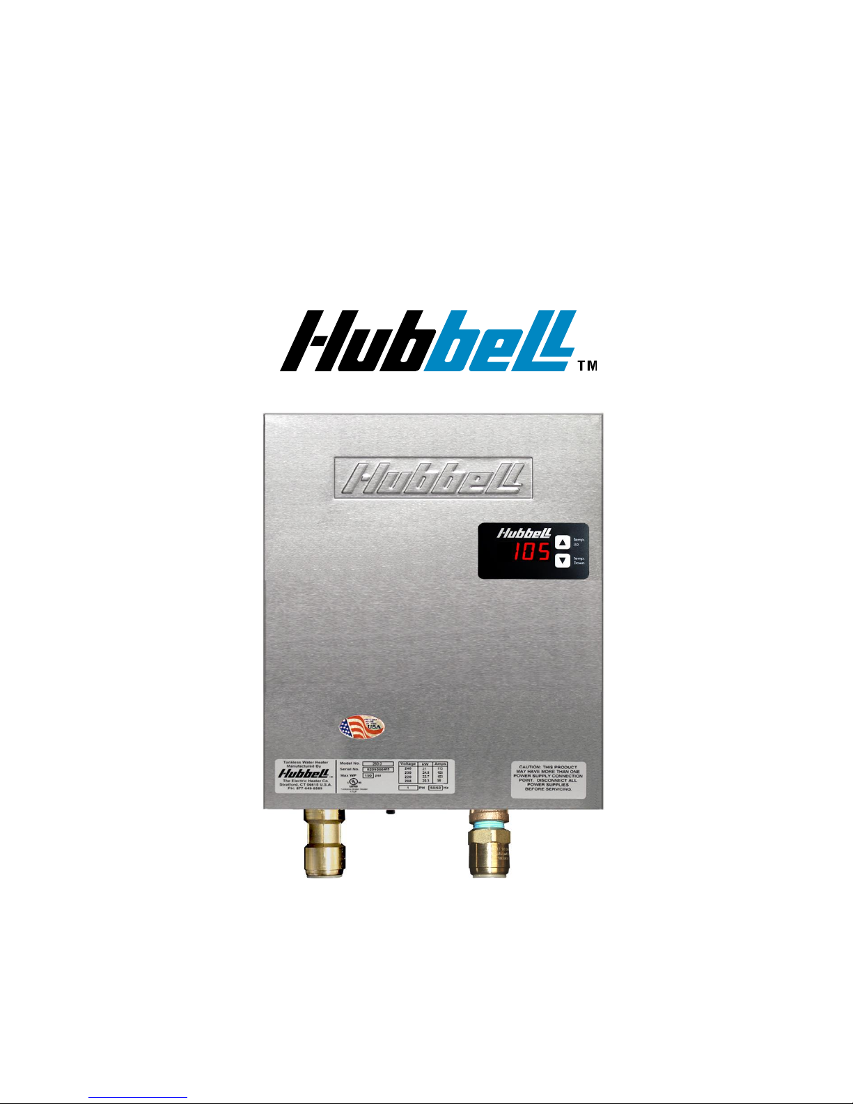
INSTALLATION, OPERATION, AND
MAINTENANCE MANUAL FOR
THE HUBBELL TANKLESS WATER HEATER
ELECTRIC HEATER COMPANY
Edition 2016A
Page 2

2
HUBBELL
ELECTRIC HEATER COMPANY
P.O. BOX 288
STRATFORD, CT 06615-0288
PHONE: (877) 649-8589
FAX: (203) 378-3593
INTERNET: http://www.buytankless.com
Important Safety Information
1. You must read and follow all instructions. Serious bodily injury or death could occur
if you ignore this warning.
2. All circuit breakers and/or disconnect switches servicing the heater must be turned off
when installing, uninstalling, or repairing this water heater.
3. The Hubbell Tankless Water Heater must be grounded.
4. The unit must be installed by a licensed electrician and plumber.
5. The unit must be wired in accordance with the current version of the National
Electrical Code (US) or Canadian Electric Code (Canada).
6. This installation must comply with all national, state, and local plumbing and
electrical codes.
7. When the heater is not within sight of the electrical circuit breakers, an additional
local means of disconnection of all ungrounded conductors must be provided that is
within sight of the appliance or a circuit breaker lockout must be used. (Ref. NEC
422.31)
8. If the Hubbell Tankless Water Heater is installed in a location where water damage
could occur in the event of a leak, it is recommended that a drip pan be installed and
connected to a suitable drain. Alternatively, an active water leak detector and shut off
valve can be installed to turn off your water supply in the event a leak is detected.
9. If water supply has a high mineral content, a water softening system is recommended.
Damage to the water heater resulting from scale or hard minerals will not be covered
under warranty.
10. When the heater is installed in a well water system or if the plumbing system is prone
to introducing air into the heater, it is highly recommended that an air separator be
installed in the cold water feed to the heater to avoid possible failure of the heating
element and/or heating chamber.
Page 3

3
TABLE OF CONTENTS
SECTION
TITLE
PAGE No.
I
TANKLESS WATER HEATER OPERATING PRINCIPLE
4
II
GENERAL DESCRIPTION AND CONSTRUCTION
5
III
INSTALLATION
10
IV
OPERATION AND MAINTENANCE
15
V
TROUBLESHOOTING
21
VI
SERVICING & REPLACEMENT OF PARTS
27
VII
PARTS LIST
32
VIII
WARRANTY
33
APP. I
SUB-PANEL WIRING DETAILS
36
Page 4

4
SECTION I – TANKLESS WATER HEATER OPERATING PRINCIPLE
How the Hubbell Tankless Water Heater Works:
For the most part, operating your new tankless water heater is very similar to using any
traditional water heater system. However, it is very important that you carefully read all of
the set-up procedures and operating instructions to ensure maximum performance and
energy savings from your new water heater.
Your Hubbell Tankless Water Heater does not store hot water like a conventional tank-type
water heater. It contains high powered heating elements that are capable of heating water
instantly on-demand as you need it. As soon as you turn on a hot water faucet, a
sophisticated flow sensor within the heater recognizes that you have turned on the water.
This sensor measures the water flow rate while two other sensors measure the incoming and
outgoing water temperature. This information is transmitted continually to the
microprocessor controller which determines the precise amount of power to send to the
heating elements to heat the water to your desired temperature. The Hubbell tankless water
heater only uses as much power as is needed to meet the demand by fully modulating the
heating elements from 0 to 100%. Since your new water heater works on a demand basis, it
will absolutely never run out of hot water no matter how many back to back showers you
run!
It is important to keep in mind that every tankless water heater has a maximum flow rate. If
you exceed this flow rate, the heater will not be capable of fully heating water. How much
hot water your heater can provide will depend on the model you have selected and your
incoming water temperature. If you live in an area of the country where inlet cold water
temperature average 55° F or you have cold winters, you will probably NOT be able to run
multiple large water demand fixtures at the same time. However, you will be able to run all
your hot water fixtures back to back without ever having to wait. You will enjoy
UNLIMITED HOT WATER. See the charts in Section II to determine the maximum flow
rates.
Moreover, since a tankless water heater eliminates the ongoing thermal losses caused by
storing hot water in a tank, you will enjoy significant energy savings over a conventional
tank type water heater.
When you use hot water from a conventional tank type water heater, you need to mix a
considerable volume of cold water to cool the hot water down to a safe, comfortable level.
You need to do this because the heater is set at an extremely high temperature to prevent it
from running out of hot water quickly. With a tankless water heater, you typically set the
temperature at a much lower level since it is capable of heating your water on demand. This
level will be much closer to the actual temperature at which you feel comfortable showering
or bathing. As such, you will no longer need to mix much cold water to run a shower or
bath; in fact, you may mix very little or no cold water. This is perfectly normal and means
that you are no longer wasting energy by overheating your water.
Page 5
5
SECTION II – GENERAL DESCRIPTION AND CONSTRUCTION
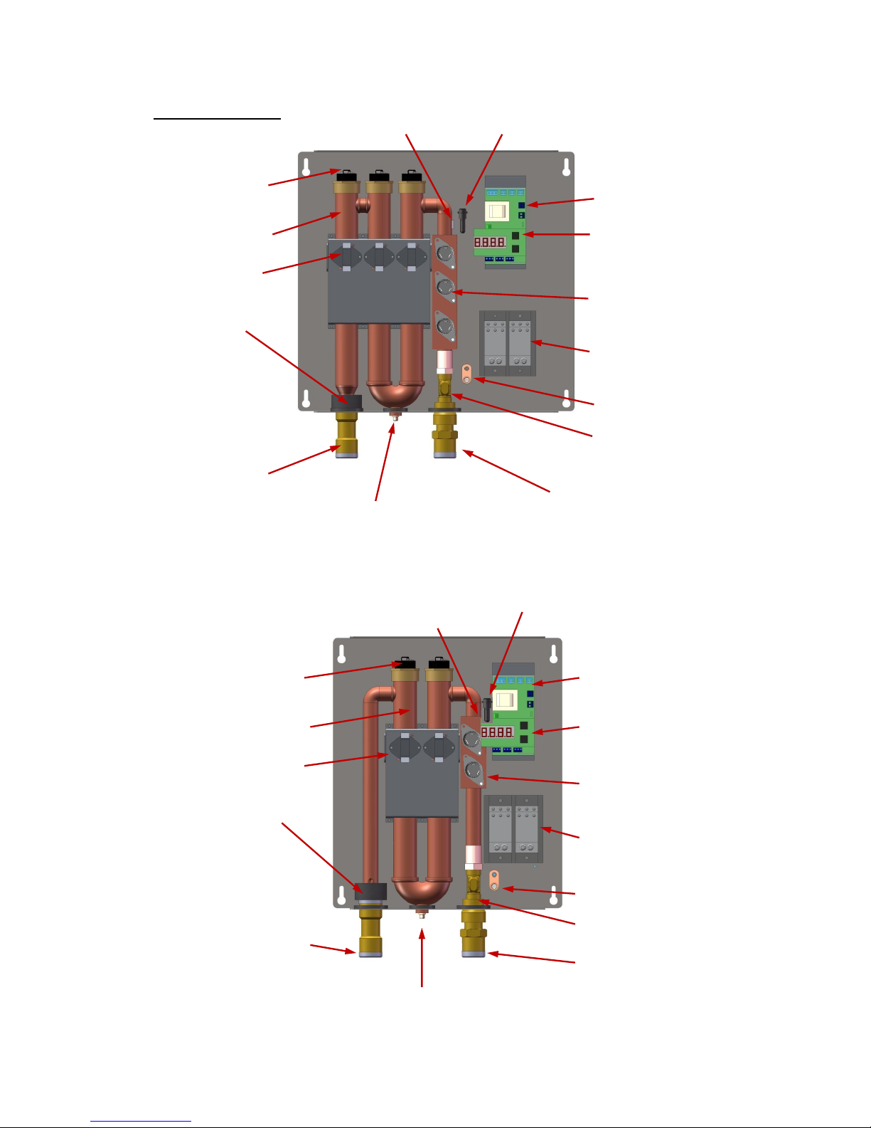
Product Overview:
Inlet Temp. Sensor Control Fuse
Heating Element Temperature
Controller
Heating Chamber LED Digital Display
(with buttons)
Hi-Limit Switch
Element Switching
Device (Triac)
Outlet Temp.
Sensor Power Distribution
Block
Ground Lug
Flow Meter
Hot Water Outlet
Cold Water Inlet
Drain
3-Element Design (Models 280-3, 240-3, and 220-3)
Control Fuse
Heating Element Temperature
Controller
Heating Chamber LED Digital Display
(with buttons)
Hi-Limit Switch
Element Switching
Device (Triac)
Outlet Temp.
Sensor Power Distribution
Block
Ground Lug
Flow Meter
Hot Water Outlet
Cold Water Inlet
Drain
2-Element Design (Models 180-2, 165-2, 145-2, and 110-2)
Inlet Temp. Sensor
Page 6

6
Hubbell Tankless Water Heater Selection Overview:
40°F 45°F 50°F 55°F 60°F 65°F 70°F 75°F
280-3
27 112.5 200 2.8 3.1 3.4 3.7 4.1 4.6 5.3 6.2
240-3
24 100.0 200 2.5 2.7 3 3.3 3.6 4.1 4.7 5.5
220-3
21 87.5 200 2.2 2.4 2.6 2.9 3.2 3.6 4.1 4.8
180-2
18 75.0 150 1.9 2.1 2.2 2.5 2.7 3.1 3.5 4.1
165-2
16 66.7 125 1.7 1.8 2 2.2 2.4 2.7 3.1 3.6
145-2
14 58.3 100 1.5 1.6 1.7 1.9 2.1 2.4 2.7 3.2
110-2 11 45.8 100 1.2 1.3 1.4 1.5 1.7 1.9 2.1 2.5
Model
No.
kW
Amps @
240V
Min. Required
Home Service
(Amps)
Max. flow (GPM) of water heated to 105°F with
incoming cold water temperature of
Note: Recovery rates (GPM) are based upon an actual supply voltage of 240 volts with no
voltage drop. If the actual supply voltage is less than 240 volts, the recovery rating (GPM) will
be reduced. Please see the wattage de-rating and flow rate formulas at the end of Section II to
determine the actual power (kW) and recovery rate (GPM) when voltage is less than 240 volts.
Tankless Pressure Drop Chart:
Technical Specifications Common to All Models:
Materials:
Copper Exchanger /
Stainless Steel Casing
Plumbing
Connection:
¾” Copper, CPVC,
or PEX
Voltage:
208-240 Volts / 1 Ph
Operating Range:
5 – 150 psi
Frequency:
50 / 60 Hz
Protection:
Thermal Auto Reset
Energy Efficiency:
98%
0
2
4
6
8
10
12
14
16
0 1 2 3 4 5 6 7 8
2-Element
3-Element
GPM
Pressure Drop (psi)
Page 7

7
Model 280-3
Our most powerful residential electric tankless water
heater. This 27 kW water heater is configured for
cold climates where the incoming water temperature
can drop below 45° F. The Model 280-3 is well suited
for homes in the northern U.S. and Canada, and those
in the southern U.S. that have large Roman-style or
Jacuzzi tubs and that have generally more demanding
water usage needs.
Technical Specifications:
Dimensions:
17” x 16.2” x 3.6”
Customer Double-Pole
Circuit Breaker / Fused
Disconnect Required:
1 x 125A or
2 x 60A or
3 x 40A
Weight:
20 lbs.
kW / Elements:
27 kW / 3 elements
Max. Amps:
112.5 A @ 240 V
Model 240-3
The 24 kW water heater is configured for climates
where incoming water temperatures are in the 50° 70° F range. The Model 240-3 is suitable as a whole
house water heater.
Technical Specifications:
Dimensions:
17” x 16.2” x 3.6”
Customer Double-Pole
Circuit Breaker / Fused
Disconnect Required:
1 x 110A or
2 x 60A or
3 x 40A
Weight:
20 lbs.
kW / Elements:
24 kW / 3 elements
Max. Amps:
100 A @ 240 V
Model 220-3
The 21 kW, water heater is configured for cold
climates where the incoming water temperature can
drop below 55° F. The Model 220-3 is well suited
for homes in the northern U.S. and Canada, and
those in the southern U.S. that have large Romanstyle or Jacuzzi tubs and that have generally more
demanding water usage needs.
Technical Specifications:
Dimensions:
17” x 16.2” x 3.6”
Max. Amps:
87.5 A @ 240 V
Weight:
20 lbs.
Customer Double-Pole
Circuit Breaker Required:
1 x 100A or
2 x 50A
kW / Elements:
21 kW / 3 elements
100 105 110 115 120 125
40 3.1 2.8 2.6 2.5 2.3 2.2
45 3.4 3.1 2.8 2.6 2.5 2.3
50 3.7 3.4 3.1 2.8 2.6 2.5
55 4.1 3.7 3.4 3.1 2.8 2.6
60 4.6 4.1 3.7 3.4 3.1 2.8
65 5.3 4.6 4.1 3.7 3.4 3.1
70 6.2 5.3 4.6 4.1 3.7 3.4
75 7.4 6.2 5.3 4.6 4.1 3.7
Outlet Temp. (°F)
Maximum Flow Rate (GPM)
Inlet
Temp.
(°F)
100 105 110 115 120 125
40 2.7 2.5 2.3 2.2 2.1 1.9
45 3 2.7 2.5 2.3 2.2 2.1
50 3.3 3 2.7 2.5 2.3 2.2
55 3.6 3.3 3 2.7 2.5 2.3
60 4.1 3.6 3.3 3 2.7 2.5
65 4.7 4.1 3.6 3.3 3 2.7
70 5.5 4.7 4.1 3.6 3.3 3
75 6.6 5.5 4.7 4.1 3.6 3.3
Outlet Temp. (°F)
Maximum Flow Rate (GPM)
Inlet
Temp.
(°F)
100 105 110 115 120 125
40 2.5 2.3 2.1 2 1.9 1.8
45 2.7 2.5 2.3 2.1 2 1.9
50 3 2.7 2.5 2.3 2.1 2
55 3.3 3 2.7 2.5 2.3 2.1
60 3.8 3.3 3 2.7 2.5 2.3
65 4.3 3.8 3.3 3 2.7 2.5
70 5 4.3 3.8 3.3 3 2.7
75 6 5 4.3 3.8 3.3 3
Outlet Temp. (°F)
Maximum Flow Rate (GPM)
Inlet
Temp.
(°F)
Page 8

8
Model 180-2
The 18 kW water heater is configured for climates
where incoming water temperatures are in the
60° -70° F range. The Model 180-2 is suitable as a
whole house water heater.
Technical Specifications:
Dimensions:
13.5” x 16.2” x 3.6”
Max. Amps:
75 A @ 240 V
Weight:
16 lbs.
Customer Double-Pole
Circuit Breaker Required:
1 x 80A or
2 x 40A
kW / Elements:
18 kW / 2 elements
Model 165-2
The 16 kW Model 165-2 is designed for moderate
climates where the coldest incoming water
temperature is 60° F or greater. As a whole house
model, the Model 165-2 is best suited to homes in the
southernmost regions of the U.S. (i.e. Southern
California, Texas, Florida, etc.), as well as Mexico
and the Caribbean.
Technical Specifications:
Dimensions:
13.5” x 16.2” x 3.6”
Max. Amps:
67 A @ 240 V
Weight:
16 lbs.
Customer Double-Pole
Circuit Breaker Required:
1 x 80A or
2 x 40A
kW / Elements:
16 kW / 2 elements
Model 145-2
The 14 kW Model 145-2 tankless water heater is
configured for climates where the lowest incoming
water temperature is above 70° F. The Model 145-2
is used primarily in warm climates as a whole house
unit in tropical climates.
Technical Specifications:
Dimensions:
13.5” x 16.2” x 3.6”
Max. Amps:
59 A @ 240 V
Weight:
16 lbs.
Customer Double-Pole
Circuit Breaker Required:
1 x 70A or
2 x 35A
kW / Elements:
14 kW / 2 elements
100 105 110 115 120 125
40 2.1 1.9 1.8 1.6 1.5 1.4
45 2.2 2.1 1.9 1.8 1.6 1.5
50 2.5 2.2 2.1 1.9 1.8 1.6
55 2.7 2.5 2.2 2.1 1.9 1.8
60 3.1 2.7 2.5 2.2 2.1 1.9
65 3.5 3.1 2.7 2.5 2.2 2.1
70 4.1 3.5 3.1 2.7 2.5 2.2
75 4.9 4.1 3.5 3.1 2.7 2.5
Outlet Temp. (°F)
Maximum Flow Rate (GPM)
Inlet
Temp.
(°F)
100 105 110 115 120 125
40 1.8 1.7 1.6 1.5 1.4 1.3
45 2 1.8 1.7 1.6 1.5 1.4
50 2.2 2 1.8 1.7 1.6 1.5
55 2.4 2.2 2 1.8 1.7 1.6
60 2.7 2.4 2.2 2 1.8 1.7
65 3.1 2.7 2.4 2.2 2 1.8
70 3.6 3.1 2.7 2.4 2.2 2
75 4.4 3.6 3.1 2.7 2.4 2.2
Outlet Temp. (°F)
Maximum Flow Rate (GPM)
Inlet
Temp.
(°F)
100 105 110 115 120 125
40 1.6 1.5 1.4 1.3 1.2 1.1
45 1.7 1.6 1.5 1.4 1.3 1.2
50 1.9 1.7 1.6 1.5 1.4 1.3
55 2.1 1.9 1.7 1.6 1.5 1.4
60 2.4 2.1 1.9 1.7 1.6 1.5
65 2.7 2.4 2.1 1.9 1.7 1.6
70 3.2 2.7 2.4 2.1 1.9 1.7
75 3.8 3.2 2.7 2.4 2.1 1.9
Outlet Temp. (°F)
Maximum Flow Rate (GPM)
Inlet
Temp.
(°F)
Page 9

9
Model 110-2
The 11 kW Model 110-2 tankless water heater is
designed for moderate climates where the lowest
incoming water temperature is above 70° F. The
Model 110-2 is a point of use or booster model in
warm climates as opposed to a whole house water
heater.
Technical Specifications:
Dimensions:
13.5” x 16.2” x 3.6”
Max. Amps:
46 A @ 240 V
Weight:
16 lbs.
Customer Double-Pole
Circuit Breaker Required:
1 x 50A or
2 x 25A
kW / Elements:
11 kW / 2 elements
Alternate Voltage Table
The tables below lists the power in kW and the amperages for each model when connected
to voltages other than 240 volts.
Wattage De-rating Formula:
Applied Voltage2
× Rated Wattage = Actual Wattage
Rated Voltage2
For example: If installing a 27 kW unit, Model 280-3, when actual voltage is 212 V,
2122
=
44,944
= 0.78 × 27,000 W = 21,060 W @ 212 V
2402
57,600
Amperage Formula:
Watts
=Amps (Single Phase)
Volts
Flow Rate Formulas:
To determine power (kW) requirement
____GPM × ____ °F T × 0.1465 = ____ kW
To determine temperature rise
____ kW × 6.824 ÷ ____ GPM = ____°F T
To determine flow rate
____ kW × 6.824 ÷ ____ °FT = ____ GPM
100 105 110 115 120 125
40 1.3 1.2 1.1 1 0.9 0.9
45 1.4 1.3 1.2 1.1 1 0.9
50 1.5 1.4 1.3 1.2 1.1 1
55 1.7 1.5 1.4 1.3 1.2 1.1
60 1.9 1.7 1.5 1.4 1.3 1.2
65 2.1 1.9 1.7 1.5 1.4 1.3
70 2.5 2.1 1.9 1.7 1.5 1.4
75 3 2.5 2.1 1.9 1.7 1.5
Outlet Temp. (°F)
Maximum Flow Rate (GPM)
Inlet
Temp.
(°F)
208 220 230
280-3 20.28 22.69 24.80
240-3 18.03 20.17 22.04
220-3 15.77 17.65 19.29
180-2 13.52 15.13 16.53
165-2 12.02 13.44 14.69
145-2 10.52 11.76 12.86
110-2 8.26 9.24 10.10
Connected Voltage
Power (kW)
Model
No.
208 220 230
280-3 97.50 103.13 107.81
240-3 86.67 91.67 95.83
220-3 75.83 80.21 83.85
180-2 65.00 68.75 71.88
165-2 57.78 61.11 63.89
145-2 50.56 53.47 55.90
110-2 39.72 42.01 43.92
Connected Voltage
Amperage
Model
No.
Page 10

10
SECTION III – INSTALLATION
WARNING: Serious bodily injury or death may occur if the following warnings are
ignored.
All circuit breakers and/or disconnect switches servicing this heater must be turned
off before installing, repairing or uninstalling this water heater.
Installation of this product is restricted to indoor locations.
Installation
MUST
be done by a licensed electrician and licensed plumber.
Locating and Mounting Instructions:
Your tankless water heater can be installed just about anywhere! Due to the small size of
your water heater, it can be mounted in many small spaces, including closets, under sinks, in
pantries, or under stair storage areas. However, there are some important guidelines to
follow that will ensure that your installation is both safe and convenient in the event that
future servicing is required.
This product is designed to be installed indoors only. You may be able to install your unit in
an outdoor location as long as it is mounted in a suitable enclosure that protects it from rain,
splashed water, direct sunlight, debris and insects. This product should NOT be installed in a
location where it may be subjected to freezing temperatures. If the water inside your tankless
water heater freezes, it can cause severe and permanent damage that is not covered under
your warranty. If you suspect that your tankless water heater may have frozen, do not turn
on the heater until it has thawed and you have inspected the system for leaks.
When selecting an installation location, give consideration to your existing plumbing
configuration, location of your main electrical panel, and location of your bathroom, kitchen
and laundry area. Try to choose a location that does not require you to make major
plumbing alterations, that is close to your main electrical panel (this will reduce the amount
of wire that you need to install), and that is physically close to the hot water fixtures that you
use most often. By locating the heater close to the points-of-use, you will reduce the amount
of time it takes for the hot water to travel from the water heater to your faucet. You should
also give consideration to future servicing. Do NOT locate the water heater in a location
that is difficult to access. In most cases, installing your tankless water heater in the same
location as your old conventional tank-type water heater will make the most sense.
You should avoid installing your tankless water heater in a location prone to excessive
humidity, moisture, or dust, or in an area where it may be splashed with water or other
liquids. Do NOT install under water pipes or air conditioning lines that might leak or
condense moisture that could then drip onto the heater. Do NOT install above electrical
boxes or junctions.
If you plan to install your water heater on a second floor or in a heated attic space, make sure
that you follow all code requirements for such installations as required for your area. We
recommend that you install a drip pan (connected to a drain) below the water heater to avoid
property damage in the unlikely event of a leak. Alternatively, you can install an active
water leak detector and shut-off valve designed to turn off your water supply in the event
that a leak is ever detected.
Mounting the unit:
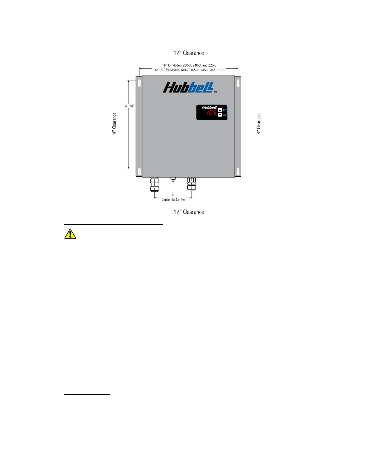
Leave a minimum of 4” to both sides and 12” on the top and bottom of the unit.
Mount the water heater securely to the wall by putting four (4) screws through the
mounting holes.
Page 11
11
Install a ¼” diameter bead of sealing caulk around the entire perimeter of the heater
between the heater back panel and the wall. This prevents any moisture or debris
from accumulating.
Plumbing Installation Instructions:
IMPORTANT INFORMATION:
Ensure all fitting installations comply with local plumbing and building codes.
This water heater does not require a temperature and pressure (T&P) relief valve.
You may install a T&P relief valve if the county, city or state plumbing code requires
it.
Installations in the Commonwealth of MASSACHUSETTS and KENTUCKY require
a
T&P
relief valve.
When connecting to a plumbing system that utilizes Flex or PVC, a
T&P
relief valve
should be used as added safety.
Do not connect the unit directly to CPVC pipe. You must use at least three feet of
copper pipe prior to connecting to any CPVC connection.
WARNING:
Do not solder any pipes with the unit connected to the pipes. Doing so
will damage the flow meter and void your warranty.
Before energizing the heater, run water for a minimum of three (3) minutes and
verify that all air has been removed.
Installation of an air separator device is recommended for installations where air can
be easily introduced into the water system (i.e. Well water systems, lake pumps, and
other municipal systems).
A shut off valve MUST be installed on inlet side of unit. A shut off valve on the
outlet is recommended.
Pipe Preparation:
Cut the tube so that the ends are square. WARNING: Ensure that there are no burrs or
damage to the cut end. This will prevent any damage to the internal o-ring.
Once the tubing end is cut square and clean, mark the pipe to be installed at a distance
of 1 ¾” from the end of the pipe. This is the insertion depth.
Check that fittings and tubing are clean, in good condition and are free from damage
and foreign objects.
Page 12
12
Flushing the Line:
Before connecting the copper pipe to the water heater, it is extremely important to
flush the lines to eliminate all plumbing paste, residue, or debris in the lines.
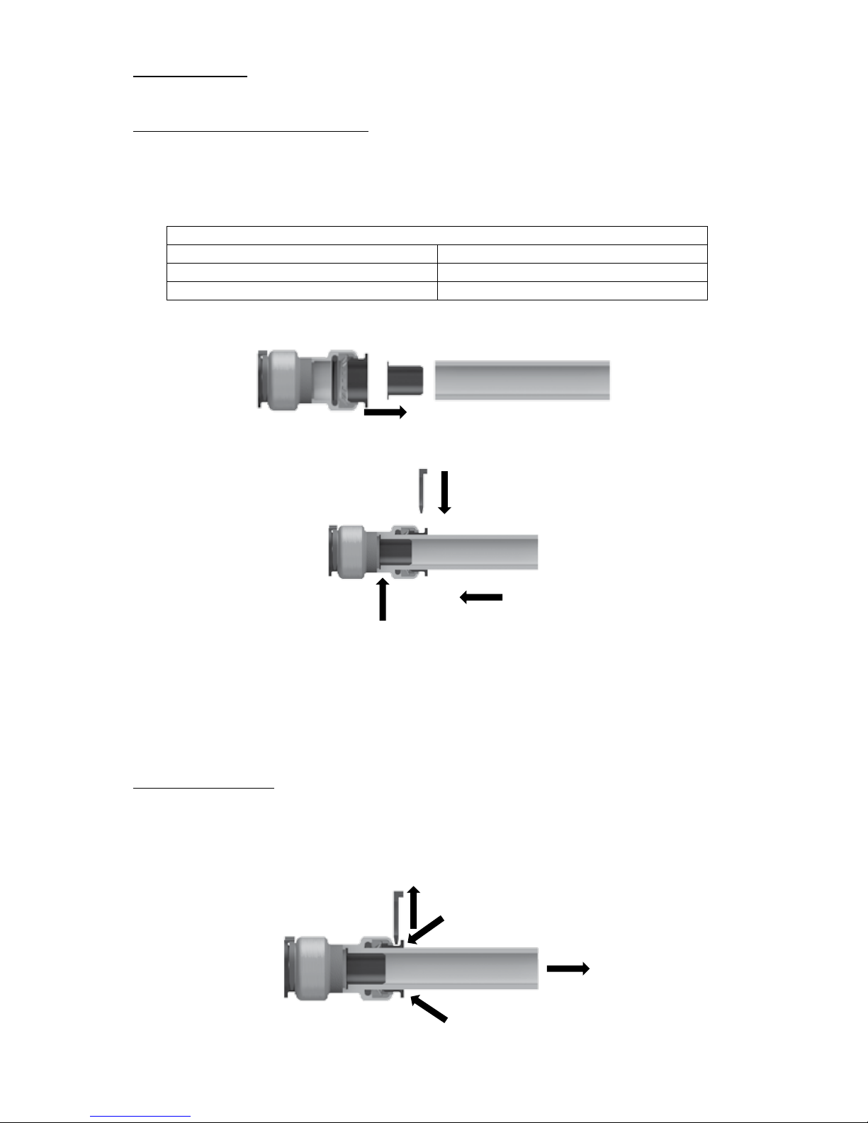
Installation to Quick-Connect Fitting:
Cut the pipe or tubing squarely and inspect the outside diameter of the pipe or tubing
to be sure there is no damage, nicks, burrs, or debris.
Deburr and clean pipe or tubing as necessary.
Use the insertion depth specified in the table below.
Insertion Depth Guide
Size
Insertion Depth
¾” CTS
1 1/8”
1” CTS
1 ¼”
If using PEX tubing, insert the supplied stiffener into the end of the pipe.
Make certain to push the tubing completely into the fitting until it comes into contact
with the internal tube stop.
Insert push ring clip.
Connect the cold water line to the water heater inlet marked cold water. Connect the
hot water line to the water heater outlet marked hot water.
After inserting both fittings, open the hot water faucet and allow water to run
through the water heater for at least three (3) minutes, cycling the flow on and off
every minute. This process clears all the air from the lines and must be performed
prior to turning on the power at the unit.
WARNING:
Failure to do this may
damage the flow meter or heating elements and will void your warranty.
Disconnecting a Joint:
Ensure the system has been depressurized before removing fitting.
Remove push ring clip.
Push the push ring in squarely against the face of the fitting.
With the push ring held securely in this position, the tubing can be removed.
Tube Stop
Page 13
13
Checking for Leaks and Purging Air:
If unit has been wired, verify all circuit breakers supplying power to the unit are
turned off.
Open all hot water taps supplied by the unit and inspect water connections for leaks.
With all hot water taps still open, allow the water to run for a minimum of 3
minutes. Inspect each tap to ensure all air in the lines has been purged. This process
purges all the air from the water lines and MUST be performed prior to turning on the
power at the unit.
WARNING:
FAILURE TO FOLLOW THIS STEP CAN CAUSE
PERMANENT DAMAGE TO THE HEATING ELEMENTS.
Close all hot water taps.
Close all hot water taps.
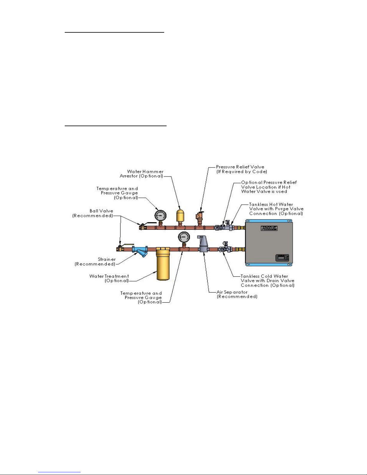
Typical Accessory Piping (Optional)
Page 14

14
Electrical Installation Instructions:
IMPORTANT INFORMATION:
The unit must be wired in accordance with the current version of the National
Electrical Code (US) or Canadian Electric Code (Canada).
The unit must have its own independent circuits.
When the heater is not within sight of the electrical circuit breakers, an additional
local means of disconnection of all ungrounded conductors must be provided that is
within sight of the appliance or a circuit breaker lockout must be used. (Ref. NEC
422.31)
Wire entry must be through the electrical KO provided in the bottom of the unit.
For Canada, per Canadian Electric Code, C22.1-02, the unit must be wired by a single
feed installation with one (1) double-pole circuit breaker.
For US, the unit may be wired by a single feed installation with one (1) double-pole
circuit breaker or by a multiple feed installation with multiple double-pole circuit
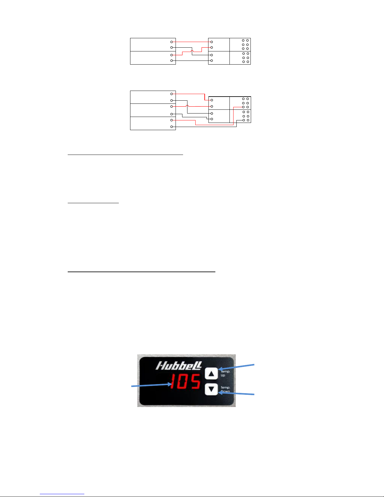
breakers as shown below.
Wiring to the water heater:
Connect the power wire from the main panel to the power distribution block.
Connect the main ground wire to the ground lug in the heater.
Make sure the connections are securely tightened.
Electrical Specifications:
Hubbell Tankless Model No.
110-2
145-2
165-2
180-2
220-3
240-3
280-3
kW @ 240V
11
14
16
18
21
24
27
Amps @ 240V
45.8
58.3
66.7
75.0
87.5
100.0
112.5
Min. Recommended
Amperage to Home
100
100
125
150
200
200
200
Multiple Circuit Installation: (See schematic below)
Minimum Double-Pole Circuit
Breaker Size
(quantity x amps) (US only)
2x25
2x35
2x40
2x40
2x50
2x60
2x60
3x40
3x40
Min. Feed Wire Size at 75°C
THHN or Equivalent
8 8 8 8 8
6 6 8
8
Single Circuit Installation:
Minimum Double-Pole Circuit
Breaker Size
(US and Canada)
50
70
80
80
100
110
125
Min. Feed Wire Size at 75°C
THHN or Equivalent
8 6 4 4 3 2 1
□ Tankless water heaters are considered a non-continuous load.
□ If 3 circuits are used, it is acceptable to install two conductors in one line side port and
the third conductor in the second line side port of the power distribution block.
Alternatively, one conductor may be installed in each line side port and the third
conductor in an open load side port of the power distribution block.
□ 60°C or 90°C wire may be used. Refer to NEC table 310.16 for sizing.
□ Conductors should be sized to maintain a voltage drop of less than 3% under load.
Page 15
15
Alternate Voltage Configuration Settings:
The unit is factory configured and optimized for 240 volts. If the actual voltage
supplied is less or equal to 230 volts, set the power factor in the configuration menu
(see Temperature Controller User Interface Instructions in Section IV) according to
the Alternate Voltage Table in Section II.
Sub-panel Wiring:
When your new Hubbell Tankless Water Heater is to replace an existing tankless
water heater that utilizes a sub-panel with circuit breakers and you are keeping the
existing sub-panel, see Appendix I for additional wiring details.
SECTION IV – OPERATION AND MAINTENANCE
First Use of your Hubbell Tankless Water Heater:
Once the water supply is on and air has been purged from the system, power the unit on at
the main panel. The unit is now operating automatically. When water flows through the unit,
the heating elements turn on to heat the water to the displayed setpoint temperature. When
the water flow stops, the heating elements turn off.
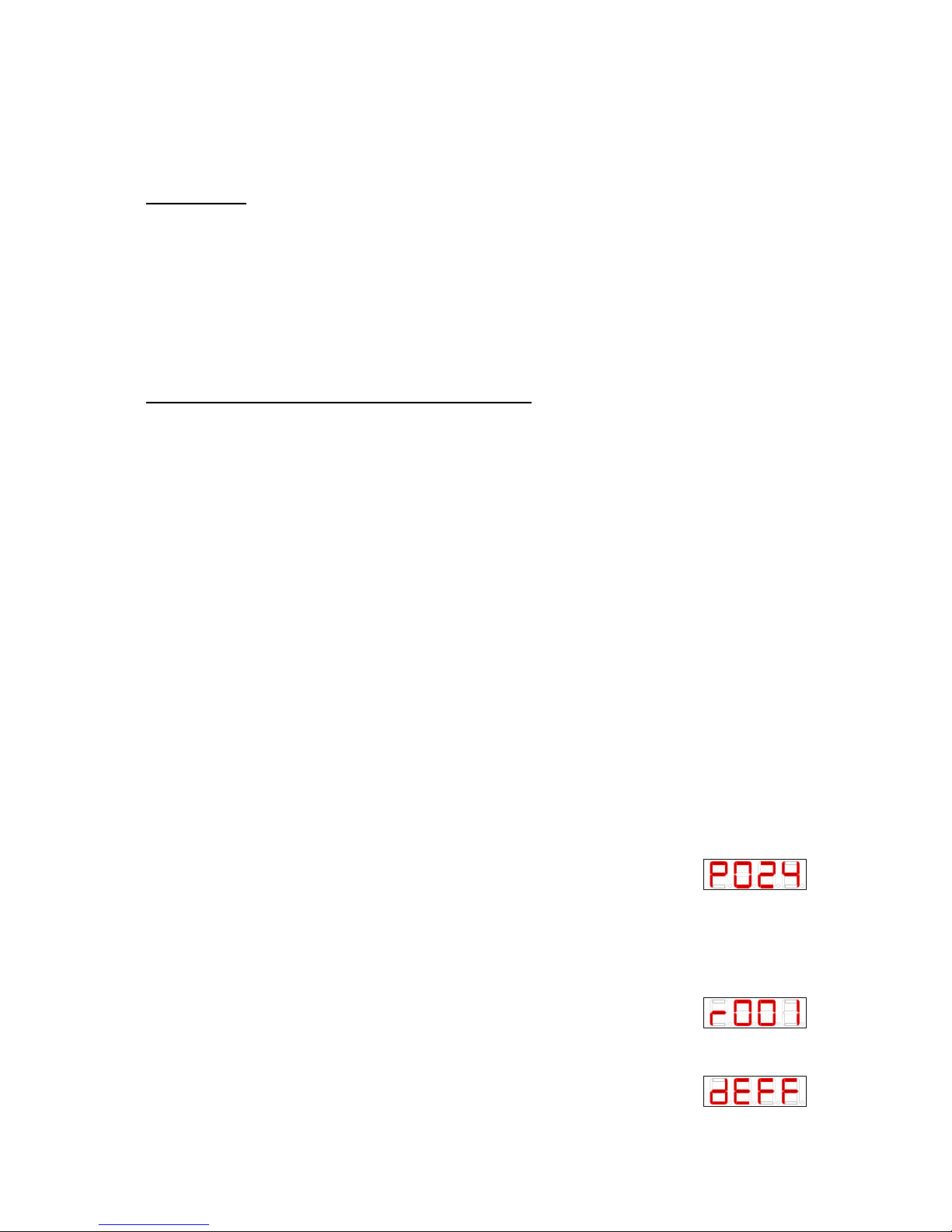
You can adjust the setpoint upward or downward by pressing the UP or DOWN button.
Displaying Celsius or Fahrenheit degrees and adjusting other settings for your tankless water
heater can be done via the configuration menu, described below.
Upper Button to
Increase Temperature
Digital Display
Lower Button to
Decrease Temperature
Most people feel comfortable showering or bathing at a temperature between 98° and
105°F (37° to 41°C). We recommend that you set the output water temperature of
your water heater in the range of 105° - 110°F (approx.41° - 43°C). This will ensure
you have adequate hot water to meet all of your household needs while also
maximizing your available water flow rate, reducing the risk of scalding to children
and the elderly, and increasing the energy savings you achieve.
Circuit Breaker 1
Circuit Breaker 2
Circuit Breaker 1
Circuit Breaker 2
Circuit Breaker 3
Tankless Power
Distribution Block
L1
L2
Tankless Power
Distribution Block
L1
L2
2 Circuit Breaker Installation
3 Circuit Breaker Installation
Page 16
16
NOTE: All newer model dish washing machines are equipped with an internal
heating element, and most clothes washing detergents are now designed for use in
cold and warm water. There is no longer a need to set your water heater to a
temperature above 125°F. Temperatures above this level (which most traditional water
heaters are set to deliver) can cause serious scalding injuries to small children or
elderly persons in your home.
Maintenance:
The Hubbell Tankless Water Heater requires no maintenance other than to
periodically check around the outside of the unit for leaks. If a water leak is detected
from your water heater, turn off the water supply at the shut-off valve on the inlet side
of the water heater, turn off the power to the heater at the main electrical panel and
call a service technician or plumber for evaluation and repair.
When any maintenance is performed on the water heater or the plumbing system that
may introduce air into the water supply pipes, it is important to turn the power off to
the water heater and purge the air out of the lines before restoring power to the unit.
See Checking for Leaks and Purging Air in Section III.
Temperature Controller User Interface Instructions:
1. The display is always on when power is applied to the unit:
a. To turn the unit OFF, press and hold the DOWN button until display shows
OFF.
b. The controller will preserve all its settings during any power outage or
disconnect.
2. To change setpoint temperature (the temperature is fully adjustable in 1° increments).
a. Press the UP or DOWN button to change the setpoint temperature.
b. Pressing and holding either the UP or DOWN button will fast scroll.
3. Configuration Menu.
a. To enter configuration menu, press and hold the UP and DOWN buttons
simultaneously for 7 seconds. (Note that the display will change during the time
you are holding the buttons. You are in the configuration menu and can release
the buttons when the first character of the display is ‘P’).
b. To scroll through menu items, press the UP or DOWN button.
c. To leave the configuration menu, wait 7 seconds without pushing any buttons.
d. To make a change to a specific configuration menu item, simultaneously press
the UP and DOWN buttons. The menu item setting will now flash indicating it
can be changed.
e. To scroll through menu item settings, press the UP or DOWN key.
f. When the desired setting is displayed, simultaneously press the UP and DOWN
buttons to lock in the selection and return back to the configuration menu.
g. Configuration Menu Items:
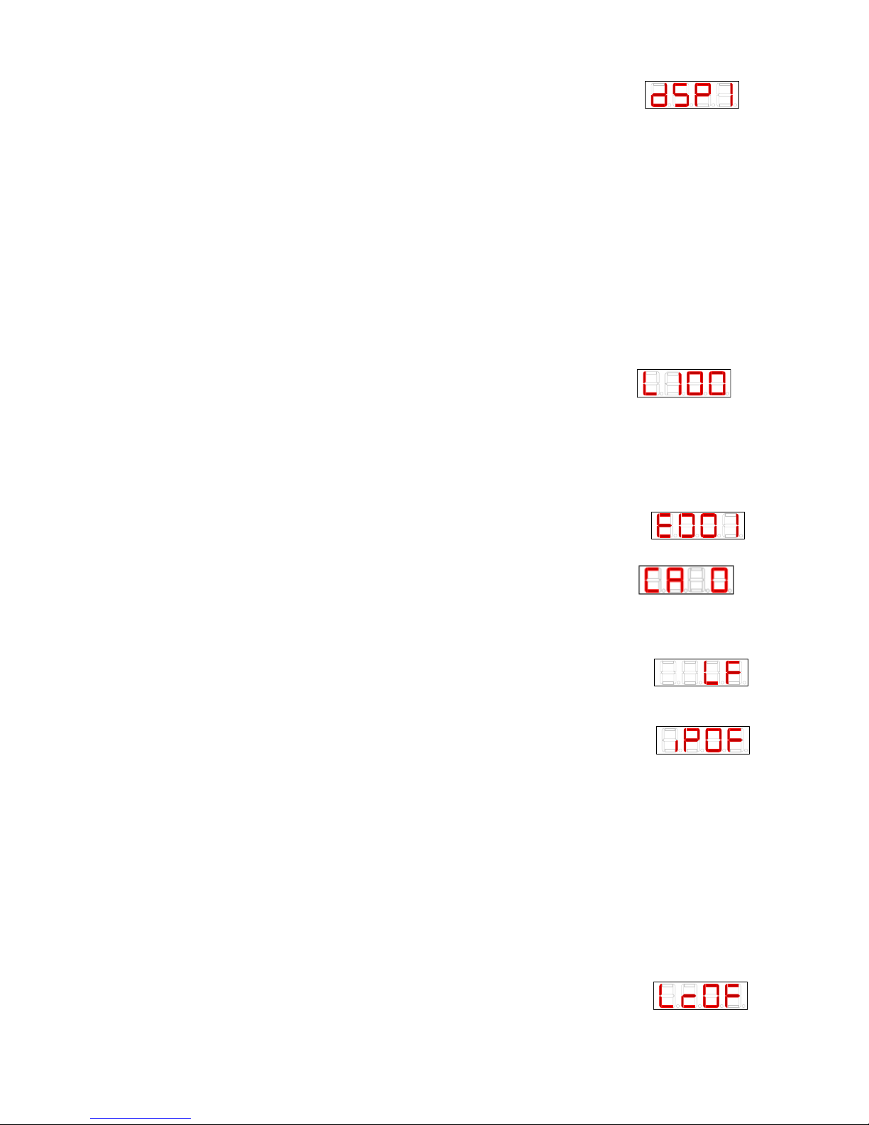
i. Power Setting - Sets the total kW rating of water heater.
1. P###, where ### is adjustable from 001 to 054 (Note
that the kW selection should equal the kW based
upon the actual voltage measured to the heater. Please see the
nameplate on the front cover of the heater for a listing of kW
ratings at various voltages).
ii. Temperature Range – Sets the temperature adjustment range
1. r001, 60° to 140°F (15°-60°C) (Factory Default)
2. r002, 32° to 194°F (0°-90°C)
3. r003, 32° to 104°F (0°-40°C)
iii. Display units – Sets the display units to either Fahrenheit/Gallons or
Celsius/Liters.
1. dEFF, for degrees Fahrenheit and Gallons. (Factory
Default)
2. dECC, for degrees Celsius and Liters.
Page 17
17
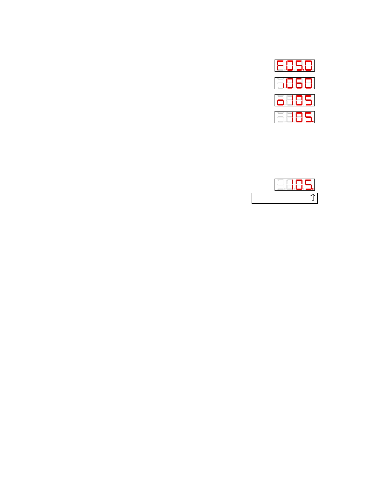
iv. Normal Display Mode– Sets the display to show various values.
1. dSP1, to display setpoint temperature only. (Factory
Default)
a. setpoint is displayed as ###
2. dSP2, to display measured inlet temperature intermittently with
setpoint temperature.
a. Inlet temperature is displayed as i###
3. dSP3, to display measured outlet temperature intermittently with
setpoint temperature.
a. Outlet temperature is displayed as o###
4. dSP4, to display measured flow rate intermittently with setpoint
temperature
a. Flow rate is displayed as F##.#, in tenths of a gallon or liter.
5. dSP5, to display inlet temp, outlet temp, flow rate and setpoint all
intermittently.
v. Power Limiting Factor – Sets the % of heater output allowed by the
controller
1. L###, where ### is a percentage from 001 to 100
(Factory Default 100). This feature allows a user to
limit the kW rating of the unit by a specific percentage and effectively
lower the total amp draw of the unit.
vi. Heater Quantity – Sets the controller to perform calculations using the
number of heating elements in the unit.
1. E001, for one heating element and all 3-phase units
2. E002, for two heating elements
3. E003, for three heating elements
4. E004, for four heating elements
vii. Calibration – Used to calibrate the heater. (For factory use only)
1. CA #, where ## equals the degrees of calibration from
-3 to 3. Default is 0.
viii. Low/High Flow – Sets the unit as either a low flow or high flow unit.
1. LF, for low flow (Factory Default).
2. HF, for high flow (NOT TO BE USED WITH THE MODELS
LISTED IN THIS MANUAL).
ix. Remote Control – Sets the operation of the remote control
function (see Priority and Remote Controls in this section).
1. iPOF, disables the remote control (Factory Default).
2. iPHi, 24VDC signal or closed relay connected to P2 and
P3 will allow the heater to operate and loss of 24VDC
signal or open relay connected to P2 and P3 will inhibit the heater
operation.
3. iPLo, 24VDC signal or closed relay connected to P2 and P3 will inhibit
the heater operation and loss of 24VDC signal or open relay connected
to P2 and P3 will allow the heater to operate.
x. Display Lock – Allows the user to lock the heater parameters. When the
display is locked the temperature setpoint cannot be changed and although the
configuration menu will still be accessible, no changes can be made to any
parameters, except to change the display lock. With the display lock on,
attempting to change the temperature setpoint will cause the display to show,
Locd.
1. LcOn, to turn the display lock on.
2. LcOF, to turn the display lock off (Factory Default).
xi. Software Version – Displays the version number of the
software
1. Sd##, where ## is the version of the display software.
Page 18
18
POINT IS FLASHING
2. Sb##, where ## is the version of the main board software.
h. After this menu item, the configuration menu cycles back to the first item.
4. Diagnostic Menu Display
a. To display common diagnostic data useful for troubleshooting, when in normal
display mode press and release the UP and DOWN buttons
simultaneously.
b. The display will intermittently display the following values: flow
rate (F##.#), measured inlet temp (i###), measured outlet temp
(o###), setpoint (###).
c. These values and settings will continue to display and scroll until
either the UP or DOWN button is pressed. The display then returns
to normal display mode.
5. Configuration Settings Display
a. To display all configuration settings, when in normal display mode press and
release the UP and DOWN buttons simultaneously twice.
b. The display will scroll through all configuration settings.
c. The display will continue to scroll until either the UP or DOWN button is
pressed and will then return to normal display mode.
6. Power Rate Display
a. The decimal point in the display’s rightmost digit is a visual
indicator of how much power is required to meet the demand. A
blinking decimal point indicates that the triac is being sent
a signal to energize and thus turn the element on. The
decimal point light will blink at a faster rate as the controller is calling for more
heat. When the unit is calling for full power the light is solid.
b. If the amount of power required exceeds the capacity of the heater, then the
entire display will intermittently flash. (Note that the display will only flash
when the display configuration is set to ‘dSP1’.)
7. Cost Calculator – Allows the user to view the amount of power and hot water
consumed and the cost of operation.
a. To display the Cost Calculator values, when in normal display mode press and
release the UP and DOWN buttons simultaneously three times.
b. The display will scroll through the Cost Calculator Values since last reset
i. C###, where ### equals the total cost of operation
ii. ####, where #### equals the total number of kW∙Hrs consumed
iii. H0##, where ## equals water usage up to the ten thousands place,
followed by h###, where ### equals water usage up to the hundreds
place. Example: H012, h345 equals 12,345 gallons of water used.
iv. To reset these values to 0, press and hold the UP and DOWN buttons
simultaneously for 5 seconds. When the display shows ‘0000’, the cost
calculator has been reset.
c. To enter a specific cost per kW∙Hr value, while displaying the Cost Calculator
values above press and release the UP and DOWN buttons simultaneously.
i. The display shows the cost per kW∙Hr as #.### (Factory Default 0.114)
ii. Press the UP or DOWN button to adjust the cost per kW∙Hr. Holding the
UP or DOWN buttons will fast scroll.
iii. Press the UP and DOWN buttons simultaneously to lock in the cost per
kW∙Hr.
iv. Press the UP or DOWN button to return to Cost Calculator values.
v. Press the UP or DOWN button to return to normal display mode.
Page 19
19
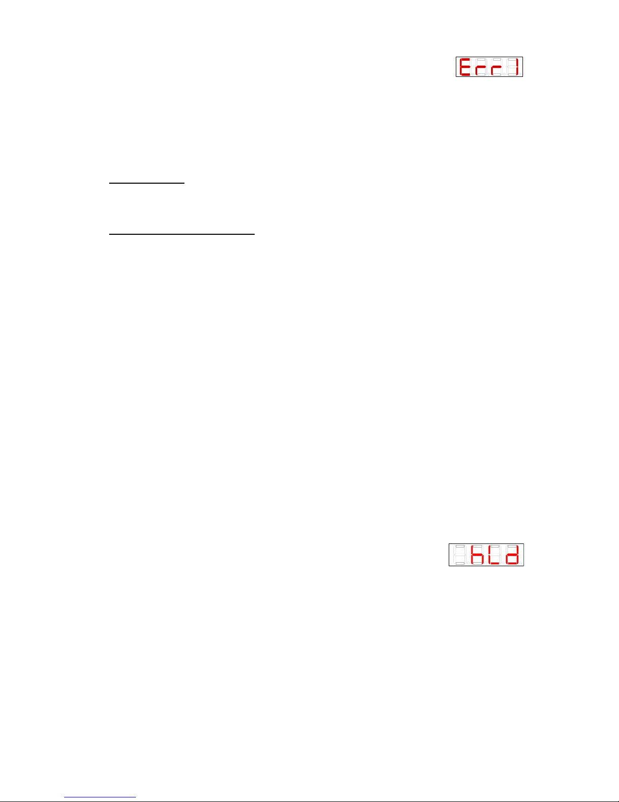
8. Error Code
a. Err1, indicates a failure of element #1
b. Err2, indicates a failure of element #2
c. Err3, indicates a failure of element #3
d. Err4, indicates a failure of element #4
e. Err5, indicates a failure of the inlet thermistor
f. Err6, indicates a failure of the outlet thermistor
g. Err7, indicates a failure of the display unit to communicate with the main board
h. Err8, indicates that water has been detected in the case
Remote Display
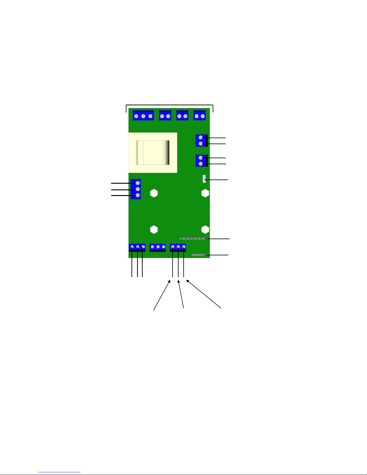
An optional remote display may be supplied and connected to the TK2000 control board as
shown below.
Priority and Remote Controls:
Optionally, the tankless water heater may be connected to another electrical device (10A @
240VAC max.) that will give priority to the water heater over that device to ensure that both do
not operate at the same time and/or the tankless water heater may be wired to a remote switch,
relay, or provided with a 24VDC signal (such as from a building maintenance system) to allow
the tankless water heater to be remotely controlled. The diagram and description below provide
details on how connections to the tankless water heater control board are to be made.
1. Priority Relay (10A@240VAC max.)
a. When the unit is demanding power (calling for heat):
i. The connection between the terminals marked C and NO are closed and
will allow power to pass through.
ii. The connection between the terminals marked C and NC are open and will
not allow power to pass through.
b. When the unit is not demanding power (not calling for heat):
i. The connection between the terminals marked C and NO are open and will
not allow power to pass through.
ii. The connection between the terminals marked C and NC are closed and
will allow power to pass through.
2. Remote Control
a. When a 24VDC signal (5mA draw max.) is supplied between terminals P1 and
P2, the heater will either operate or be inhibited (displayed as Hld) as determined
by the Remote Control settings as shown above. Loss of 24VDC signal has the
opposite effect.
b. When wired to a volt-free contact (10A max.) between terminal P2 and P3 (output
signal 24VDC@5mA), opening or closing the contact will allow the heater to
either operate or inhibit (displayed as Hld) operation as
determined by the Remote Control settings as shown above.
Page 20
20
TK2000 Control Board Wiring Detail
Remote
Display
Outlet
Thermistor
Inlet
Thermistor
Leak
Detection
F1 F2 F3
Flow
Meter
Display
Auxiliary
P1(0VDC) P2(+24VDC) P3
Remote
Control
Priority
Relay
NC
NO
C
Power and Triac Wiring
Page 21
21
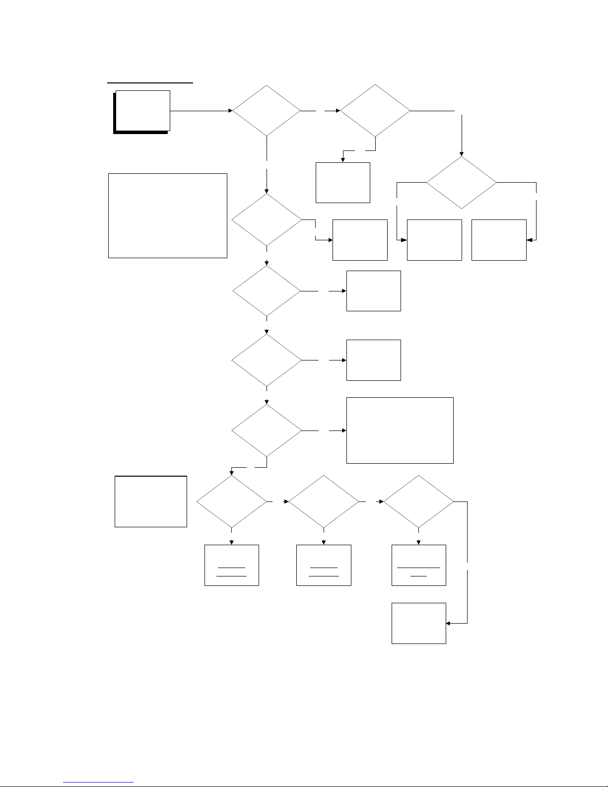
SECTION V – TROUBLESHOOTING
Initial Evaluation:
No Hot Water
or
Water is not hot
enough
Is display lit?
Is
circuit breaker or
disconnect
off?
Turn on circuit
breaker or
disconnect
No
Yes
Yes
Is
the temperature
setting too
low?
Adjust
temperature
setting
See Section III.
Is flow
too great for temp.
setting? See
Section II.
Reduce flow.
See Advanced
Troubleshooting
Yes
No
Yes
Is
there a plumbing
crossover? (See
note 1)
Yes
Consult a local
plumber for help
in correcting the
plumbing
crossover.
No
Turn off power supply to the unit.
Close installer supplied cold water
shut-off valve (if none installed,
install before proceeding).
Open all hot water taps supplied by
the unit.
Wait 5 minutes and check all taps.
Any water running is a sign of
plumbing crossover.
To check for a plumbing crossover:
No
NOTE 1
Is
an anti-scald or
tempering valve
installed?
No
No
An anti-scald or tempering valve
automatically mixes cold water even
when the faucet handle is turned to
full hot. These devices are usually
adjustable so the cold mix can be
turned off completely. Alternatively,
the temperature of the heater can be
increased if hotter water is needed.
Yes
For the final three steps,
set the unit to diagnostic
mode by pressing and
releasing the UP and
DOWN buttons
simultaneously.
Does
i### match the
actual inlet
temp.?
Does
o### match the
actual outlet
temp.?
With
water flowing, does
F##.# show
00.0?
Yes Yes
No
Go to step 6 of
Check the
Thermistor
Go to step 6 of
Check the
Thermistor
Go to step 4 of
Check the Flow
Meter
No No Yes
Is control fuse
open?
Replace Fuse
See Advanced
Troubleshooting
Yes
No
Page 22
22
Advanced Troubleshooting:
WARNING: Serious bodily injury or death may occur if the following warnings are
ignored.
This following portion of this section is intended for use by a QUALIFIED
ELECTRICIAN.
All circuit breakers must be turned off at the main panel before the cover of the unit
is removed.
This troubleshooting section will cover all the points that need to be checked from an
electrical standpoint to ensure that the Hubbell tankless water heater is working correctly
and to determine which component may need to be replaced.
Tools Required:
Phillips screwdriver
Clamp multi-meter able to read voltage and amperage (amperage readings require a
clamp type meter).
Thermometer
Pre-Operational Procedures:
1. With power to the unit turned ON, verify that the configuration settings are correct in
accordance with the Temperature Controller User Interface Instructions in Section IV.
2. TURN OFF POWER AT THE MAIN PANEL.
3. Remove the cover by unscrewing the screws located at the top (2) and the bottom (4)
of the unit.
4. Verify that the main power feed is properly connected to the power distribution block.
5. Verify all connections are tight.
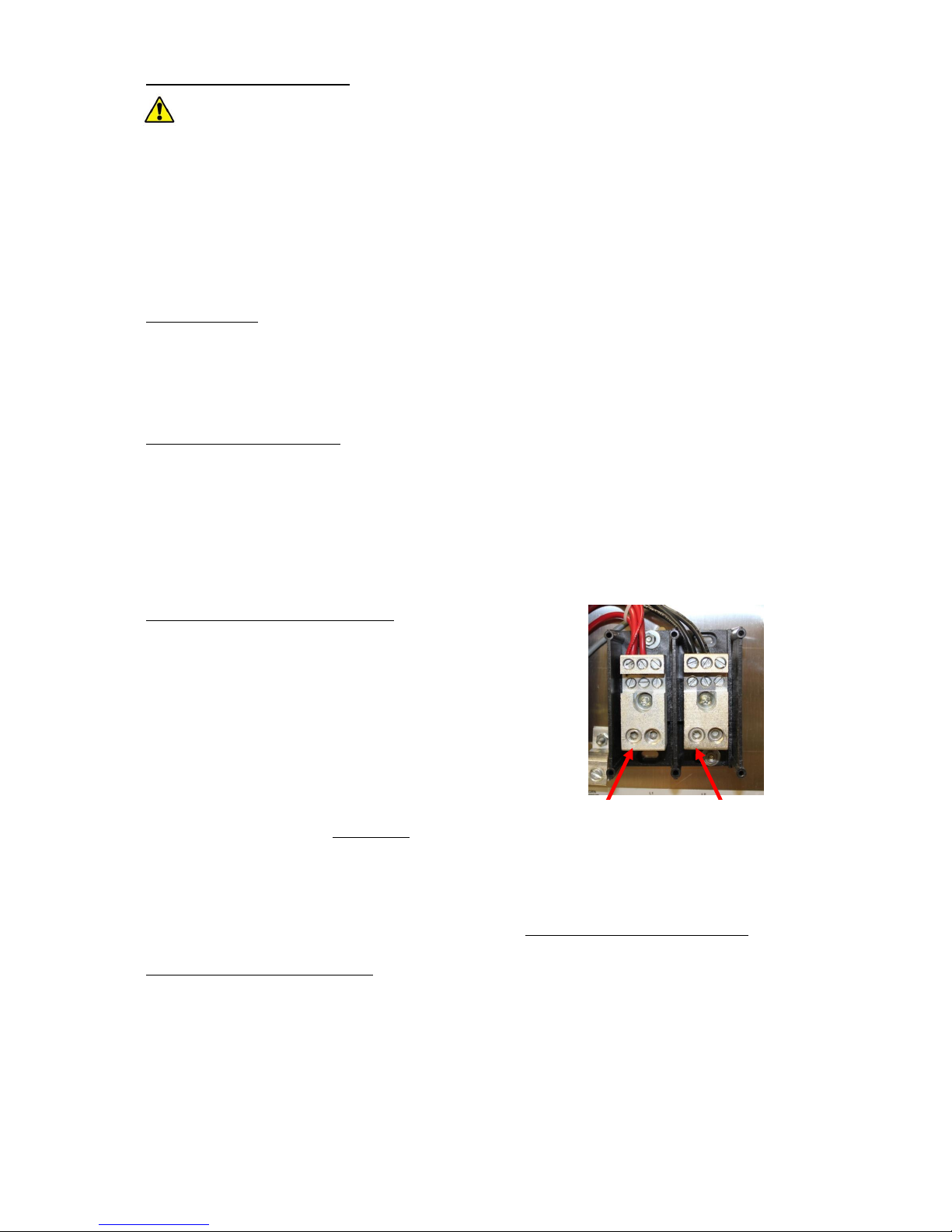
Check the Power Supply to the unit:
1. Turn on power to the unit from the main panel.
2. Using the multi-meter probes with the setting at Volts –
Alternating Current with a range 250+, place one probe
on the lower screw of the left hand side (L1) of the
power distribution block and the other probe on the
lower screw of the right hand side (L2) of the power
distribution block. A voltage reading in the appropriate
range (either 208V or 240V) should be indicated.
3. Write down the voltages below:
Volts from L1 to L2
4. If no voltage is present, verify that the breakers or disconnect on the main panel have
been turned on.
5. If the breakers are on and there is still no voltage present, contact an electrician to
troubleshoot the feed.
6. If all voltage readings are acceptable, proceed to Check the Hi-Limit Thermostats.
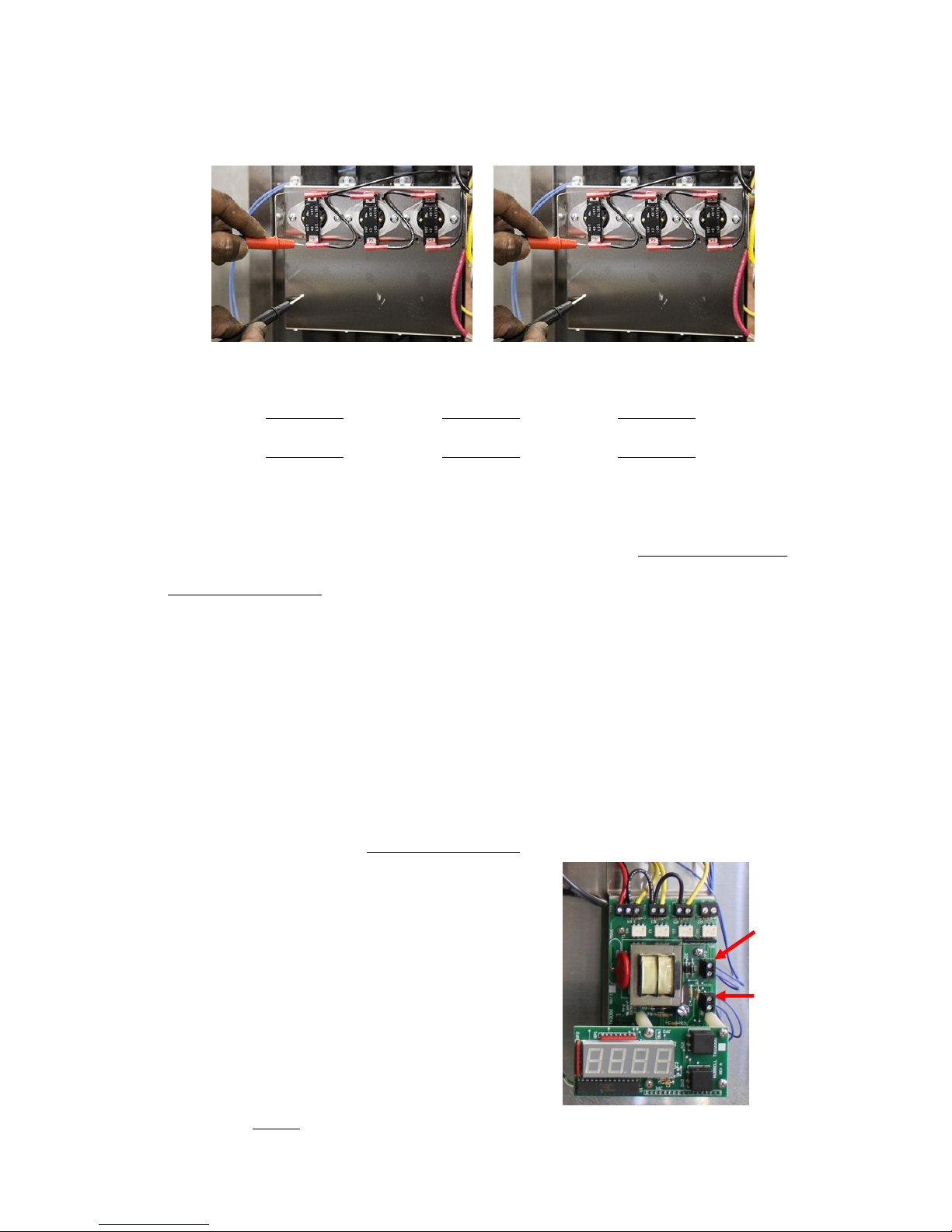
Check the Hi-Limit Thermostats:
1. The unit is supplied with safety hi-limit thermostats mounted on the plate that holds
the heating chamber in place. These thermostats allow the power from one phase of
the terminal block to flow to the heating element. If the hi-limit thermostat fails it will
not supply the heating element with power and therefore the heating element will not
turn on and produce heat.
2. Using the multi-meter probes with the setting at Volts – Alternating Current with a
range 250+, place one probe on the lower metal part of the thermostat and the other
probe to the metal plate to ground the probe. If shrink-wrap is present around the
L1
L2
Page 23
23
metal connection point to the hi-limit thermostat, cut back the shrink-wrap with a
knife to expose the metal connection. A voltage reading around 120V should be
indicated since this component is being fed by one leg of the electrical power coming
off the terminal block. Perform this step on the bottom of each hi-limit thermostat then
again on the top of each hi-limit thermostat.
3. Write down the voltages below:
Bottom
1. Volts 2. Volts 3. Volts
Top
1. Volts 2. Volts 3. Volts
4. If there is no voltage at the bottom of any hi-limit thermostat, then check the wiring
and connections between that hi-limit thermostat and the power distribution block.
5. If correct voltage is present at the bottom of the hi-limit thermostat but no voltage is
present at the top of the thermostat, then that hi-limit thermostat needs to be replaced.
6. If correct voltage is present on the top and bottom continue to Check the Thermistor.
Check the Thermistor:
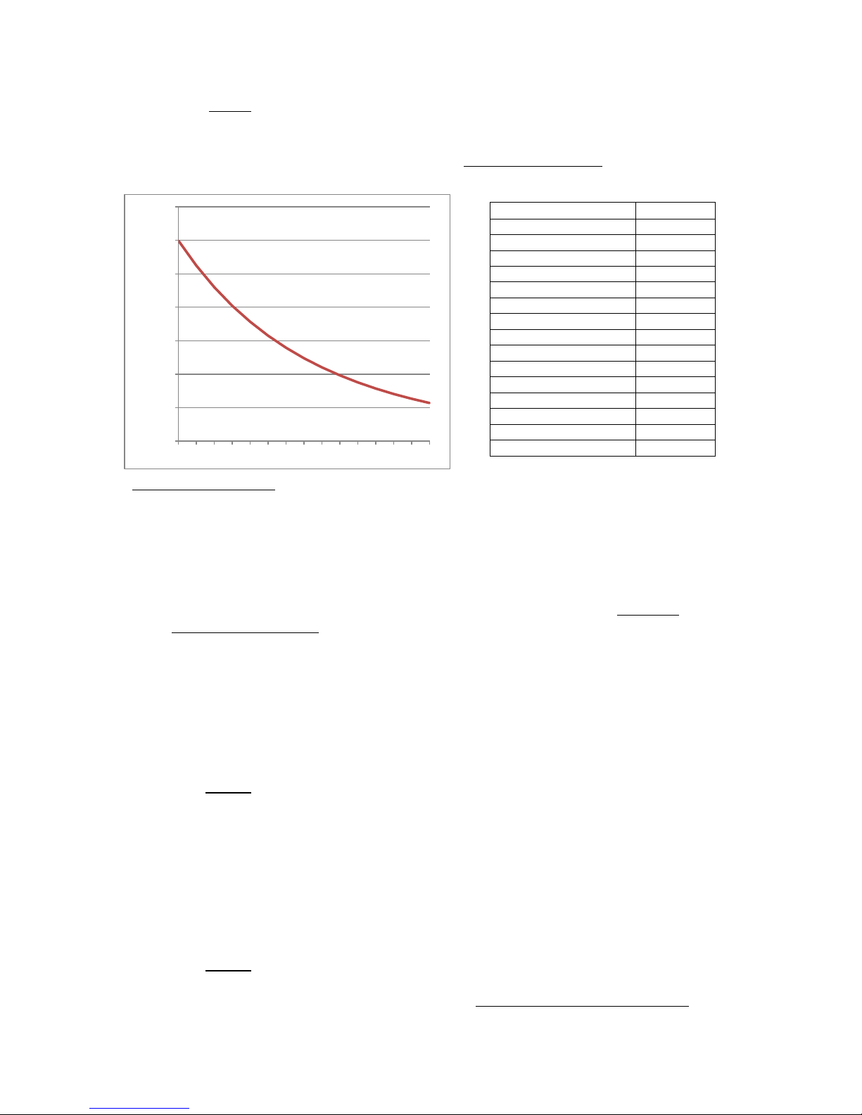
1. The thermistor is a temperature sensing device that changes resistance with changes in
temperature. It is designed to register 150,000 at 25°C (77°F).
2. Set the unit to diagnostic mode by pressing and releasing the UP and DOWN buttons
simultaneously.
3. With a thermometer, measure the temperature of the cold water and hot water at a
fixture.
4. Write down the measured and displayed temperatures below:
Cold temp.______ i###______ Hot Temp.______ o###______
5. Compare the displayed inlet temperature (i###) to the measured cold water
temperature and the displayed outlet temperature (o###) to the measured hot water
temperature. If either of these readings are significantly different continue with step 6.
Otherwise, proceed to Check the Flow Meter.
6. At the right hand side of the temperature
controller are two terminal blocks. Disconnect
the wires from the uppermost terminal block
(outlet thermistor). Using the multi-meter probes
with the setting at OHMS or , place one probe
on the end of one wire and the other probe on the
end of the other wire. An ohms reading
consistent with the chart below for the
approximate temperature of the water should be
indicated. NOTE: Alligator clips should be used.
Holding the wires in your hands will give a false
reading. Reconnect the wires.
7. Write down the resistance below:
Ohms
8. Repeat step 6 with the lower terminal block (inlet thermistor).
Outlet
Thermistor
Inlet
Thermistor
Page 24
24
0
50,000
100,000
150,000
200,000
250,000
300,000
350,000
50 55 60 65 70 75 80 85 90 95 100 105 110 115 120
9. Write down the resistance below:
Ohms
10. If either of these readings is not consistent with the chart (within ±10,000), replace
that thermistor.
11. If all ohms readings are acceptable, proceed to Check the Flow Meter.
Thermistor Chart (150,000 @ 25°C (77°F))
Temperature, °F (°C)
Ohms,
50 (10.0)
299,516
55 (12.8)
262,075
60 (15.6)
229,905
65 (18.3)
202,188
70 (21.1)
178,244
75 (23.9)
157,506
80 (26.7)
139,501
85 (29.4)
123,829
90 (32.2)
110,157
95 (35.0)
98,201
100 (37.8)
87,723
105 (40.6)
78,519
110 (43.3)
70,418
115 (46.1)
63,273
120 (48.9)
56,957
Check the Flow Meter:
1. Set the unit to diagnostic mode by pressing and releasing the UP and DOWN buttons
simultaneously.
2. Turn on a hot water tap preferably at the tub to ensure a good flow rate through the
unit and write down the displayed flow rate (F##.#) below:
F##.#______
3. If the flow rate is 00.0 then continue with step 4. Otherwise, proceed to Check the
Temperature Controller.
4. Verify that the wiring from the flow switch is connected to the control board in the
order WHITE/GREEN/BROWN from left to right.
5. With no flow on the unit, using the multi-meter probes with the setting at Volts –
Direct Current, place one probe on the terminal block where the WHITE wire is
connected (F1) and the other probe where the BROWN wire is connected (F3). A
voltage reading in the appropriate range (5V) should be indicated.
6. Write down the voltage below:
Volts
7. If the voltage reading is not in the appropriate range (5V), replace the temperature
controller.
8. Turn on a hot water tap preferably at the tub to ensure a good flow rate through the
unit and using the multi-meter probes with the setting at Volts – Direct Current, place
one probe on the terminal block where the WHITE wire is connected (F1) and the
other probe where the GREEN wire is connected (F2). A voltage reading in the
appropriate range (2.5V) should be indicated.
9. Write down the voltage below:
Volts
10. If the voltage reading is not in the appropriate range (2.5V), replace the flow meter.
11. If all voltage readings are acceptable, proceed to Check the Temperature Controller.
Page 25
25
Check the Temperature Controller:
1. At the top of the temperature controller there are 4 sets of terminal blocks. Verify the
wiring is correct as indicated in the wiring diagram specific to the model.
2. Check the voltage between the terminal block where the BLACK wire is connected
(this will be the leftmost terminal) and the metal heater chamber cover. A voltage
reading in the appropriate range (120V) should be indicated.
3. If no voltage is present, verify that the BLACK wire in the terminal block is properly
tightened and verify that the opposite end, this will be a RED wire, is properly
connected to the power distribution block, magnetic contactor, or transformer, as
applicable.
4. Check the voltage between the terminal block where the BLACK wire is connected at
the second terminal from the left and the metal heating chamber cover. A voltage
reading in the appropriate range (120V) should be indicated. Repeat this step for each
of the wires connected to the terminal blocks.
5. If no voltage is present, verify that the BLACK wire in the terminal block is properly
tightened and verify that the opposite end, this will be a RED wire, is properly
connected to the power distribution block, magnetic contactor, or transformer, as
applicable.
6. If voltage is present where the black wires connect to the terminals and there is no
display, replace the temperature controller.
7. Check the voltage between each additional wire from left to right and the metal
heating chamber cover. A voltage reading in the appropriate range (one half of the
incoming power voltage, i.e. if the incoming power is 480V, then the reading should
be 240V) should be indicated.
8. If no voltage is present, verify that the BLACK wires in the terminal block are
properly tightened and verify that the opposite ends of the BLACK wires are properly
jumpered to the previous BLACK wire connection terminal or properly connected the
magnetic contactor, as applicable.
9. Turn on a hot water tap at a fixture that will ensure a good flow rate through the unit
and set the temperature at the highest setting so the unit calls for full power.
10. Check the voltage between the terminal block where the first YELLOW wire is
connected from left to right and the metal heating chamber cover. A voltage reading in
the appropriate range (one half of the incoming power voltage, i.e. if the incoming
power is 480V, then the reading should be 240V) should be indicated. Repeat this step
for each of the YELLOW wires.
11. If no voltage is present on any one of the YELLOW wires, replace the temperature
controller.
12. If all voltage readings are acceptable, proceed to Check the Triacs (Step 1).
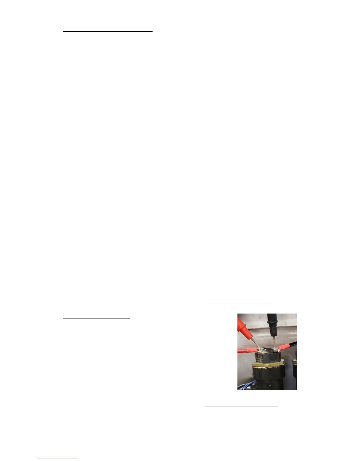
Check the Triacs (Step 1):
1. The triacs are the switching mechanism for turning the
heating elements on and off.
2. Turn on a hot water tap at a fixture that will ensure a good
flow rate through the unit and set the temperature at the
highest setting so the unit calls for full power.
3. Check the voltage between the two wires that are connected
to the top of the heating element. A voltage reading in the
appropriate range (equal to the incoming line voltage)
should be indicated.
4. If no voltage is present on any heating element, the triac
connected to that element should be replaced.
5. If all voltage readings are acceptable, proceed to Check the Heating Elements.
Page 26
26
Check the Heating Elements:
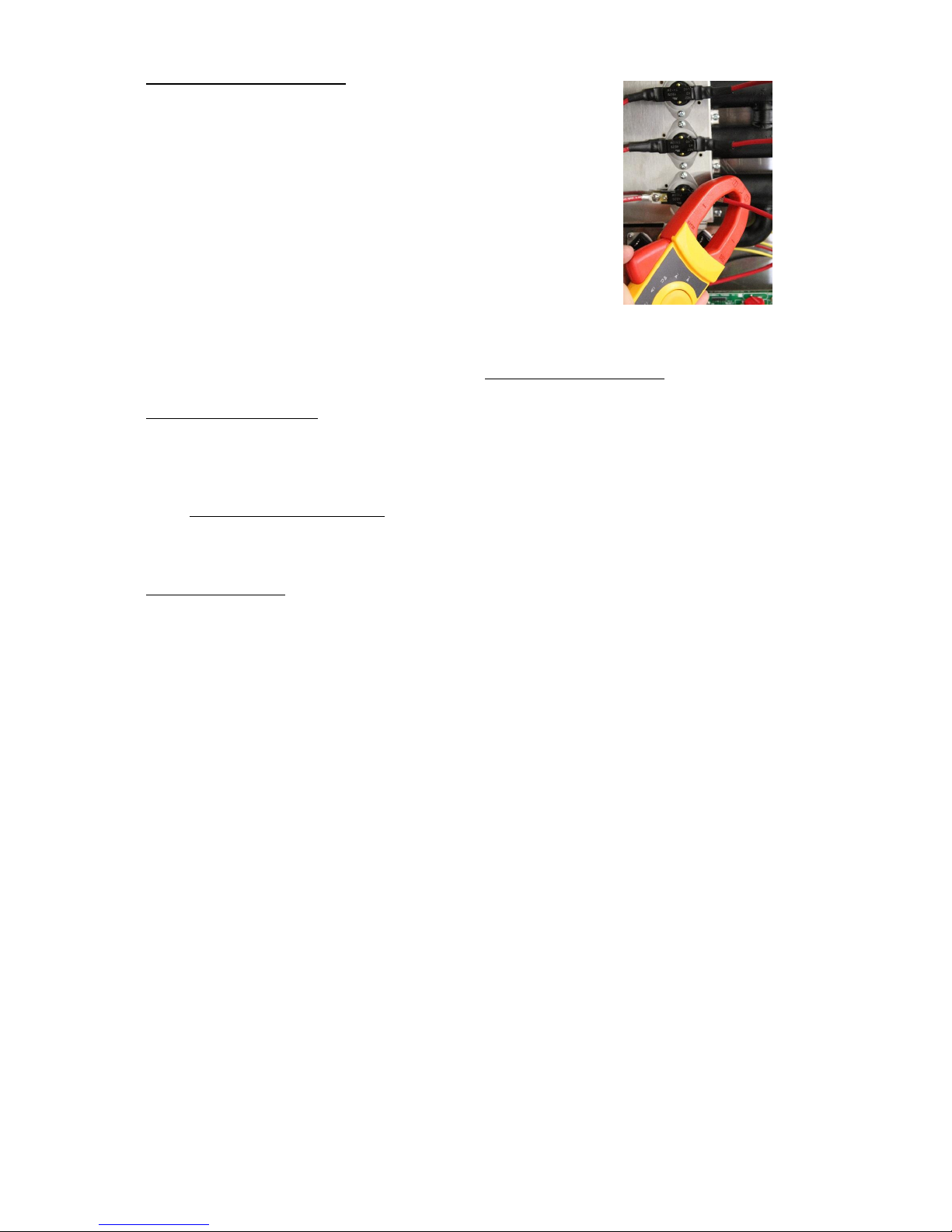
1. To check the heating element the amperage draw from each
heating element must be verified. To do this the unit must be
operating.
2. Turn on a hot water tap at a fixture that will ensure a good
flow rate through the unit and set the temperature at the
highest setting.
3. Using a clamp-on multi-meter, clamp the meter around one
of the RED wires going to the lowest heating element. The
reading should be as indicated (±5%) based on the specific
model listed in the Electrical Specification table in the
Installation section.
4. Repeat for all the heating elements.
5. If any amp reading is not within the range as indicated in the chart, that heating
element should be replaced.
6. If all readings are within range continue to Check the Triacs (Step 2).
Check to Triacs (Step 2):
1. Turn off the flow of hot water.
2. Using the clamp-on multi-meter with the setting at Amps – Alternating Current, clamp
the meter around the first, from right to left, of each RED wire that goes from the top
of the safety hi-limit thermostat to the top of the heating element (same as in step 3 of
Check the Heating Elements). The reading should be zero.
3. If any reading is not zero with the hot water turned off, then that triac should be
replaced.
Contact the Factory:
1. If you were unable to determine the problem from the above troubleshooting, please
have the electrician contact the factory.
Page 27
27
SECTION VI – SERVICING & REPLACEMENT OF PARTS
WARNING: Serious bodily injury or death may occur if the following warnings are
ignored.
This following portion of this section is intended for use by a QUALIFIED
ELECTRICIAN OR PLUMBER.
All circuit breakers must be turned off at the main panel before the cover of the unit
is removed.
When any maintenance is performed on the water heater that may introduce air into
the unit, it is important to purge the air out of the lines before allowing the unit to
power up. See Checking for Leaks and Purging Air in Section III.
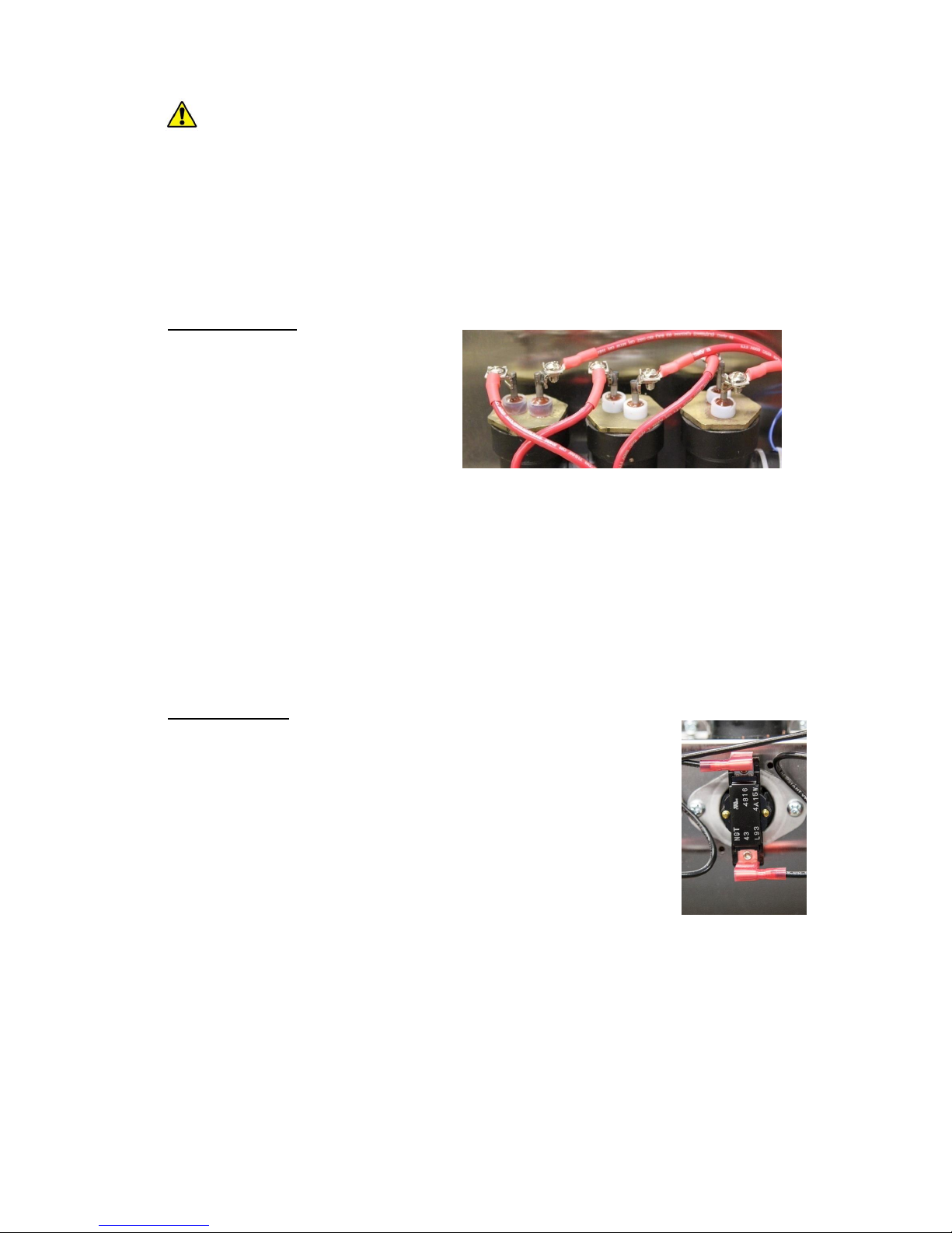
Heating Element:
Disconnect power.
Shut off cold water inlet and hot
water outlet valves.
Drain unit.
Remove cover.
Disconnect the RED power leads
from the top of the element to be
replaced.
Unscrew the element from the heating chamber coupling.
Install the replacement heating element by screwing it into the heating chamber
coupling.
NOTE: Verify that the o-ring is installed onto the heating element prior to installation.
Re-connect the power leads to the element terminals.
Re-install cover.
Open the cold water inlet and hot water outlet valves.
Bleed air from the unit. See Checking for Leaks and Purging Air in Section III.
Turn on power.
Hi-Limit Switch:
Disconnect power.
Remove cover.
Disconnect the RED power leads from the heating element and
power distribution block that connect to the hi-limit switch to be
replaced.
NOTE: The replacement hi-limit switch comes with power leads
attached. Power leads should not be disconnected from the hi-limit
switch.
Remove the two (2) screws securing the hi-limit switch to the
heating chamber cover.
Remove the hi-limit switch.
Spread a pea sized amount of the conductive thermal paste included with the
replacement kit on the back of the hi-limit switch (the portion to be installed against the
heating chamber tube).
Install the hi-limit switch to the heating chamber cover with the two (2) screws
previously removed.
Connect the power leads to the heating element and the power distribution block.
Re-install cover.
Turn on power.
Page 28
28
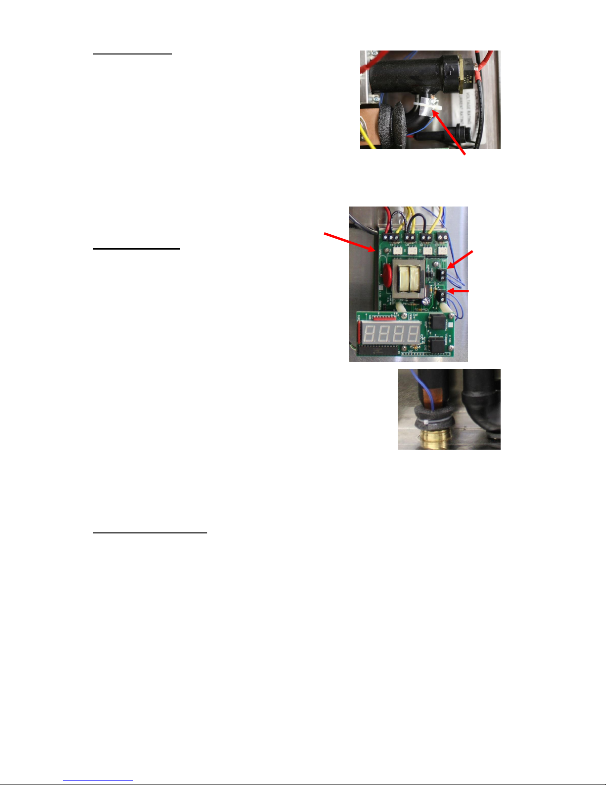
Inlet Thermistor:
Disconnect power.
Remove cover.
Disconnect inlet thermistor wires from the controller.
Cut the tie-wrap securing the inlet thermistor to the
inlet pipe and remove the inlet thermistor.
Spread a pea sized amount of the conductive thermal
paste included with the replacement kit on the inlet
pipe where the replacement inlet thermistor is to be
installed.
Secure the inlet thermistor to the inlet pipe with a new tie-wrap.
Connect the inlet thermistor wires to the controller.
Re-install cover.
Turn on power.
Outlet Thermistor:
Disconnect power.
Remove cover.
Disconnect outlet thermistor wires from the
controller.
Cut the tie-wrap securing the outlet thermistor
insulation.
NOTE: Save the insulation to cover the
replacement outlet thermistor.
Remove the aluminum tape securing the outlet
thermistor and remove the outlet thermistor.
Spread a pea sized amount of the conductive thermal paste
included with the replacement kit on the outlet pipe where the
replacement outlet thermistor is to be installed.
Secure the outlet thermistor to the outlet pipe with a new piece
of aluminum tape. Position the outlet thermistor such that the
wires are facing towards the top.
Secure the outlet thermistor insulation around the outlet thermistor with a new tie-wrap.
Connect the outlet thermistor wires to the controller.
Re-install cover.
Turn on power.
Temperature Controller:
Disconnect power.
Remove cover.
Mark the wires going to the controller so they can be re-connected in the same places
upon replacement.
Disconnect all the wires from the controller.
NOTE: The display may need to be removed to access the wires from the flow meter.
The display can be removed by removing the four (4) screws securing the display to the
controller standoffs and then pulling the display from the socket.
Remove the two (2) screws securing the temperature controller to the controller stand.
Install the replacement controller with the two (2) screws removed in the last step.
Re-connect the wires to the temperature controller in the same locations they were
previously disconnected from.
Re-install cover.
Turn on power.
Outlet
Thermistor
Inlet
Thermistor
Inlet Thermistor
Temperature
Controller
Page 29
29
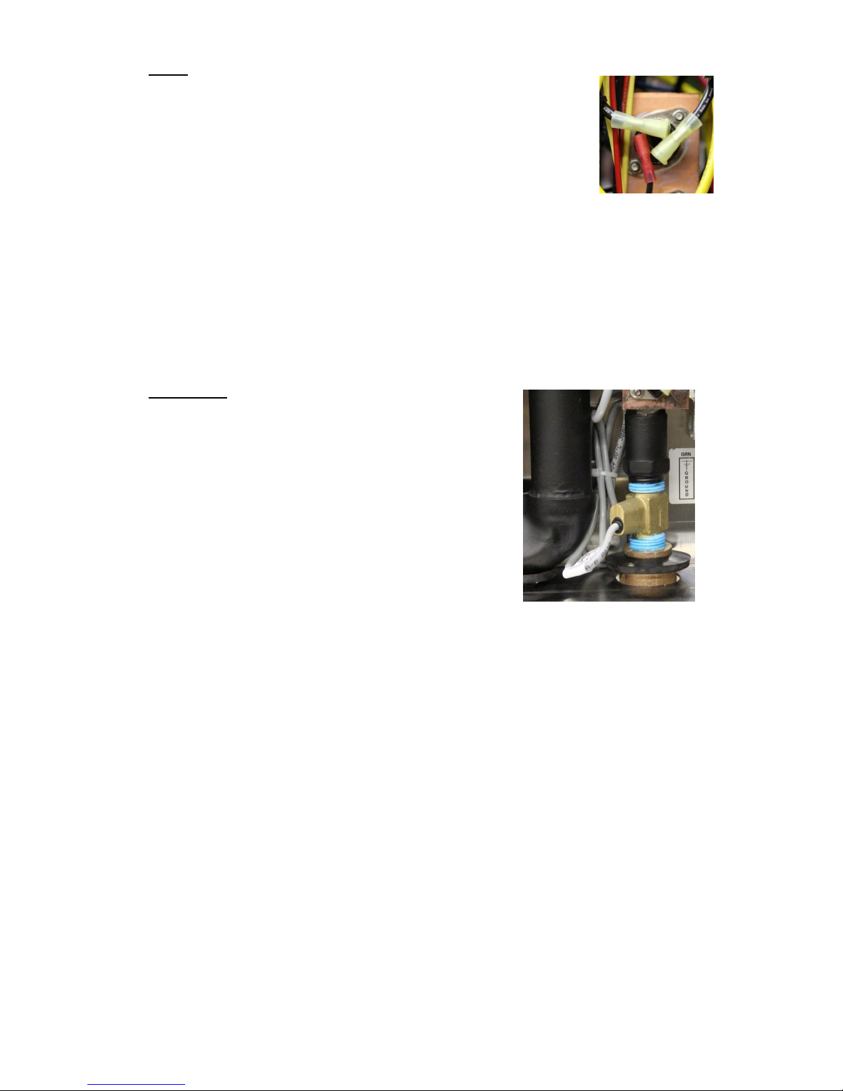
Triac:
Disconnect power.
Remove cover.
Disconnect the wire from the heating element, the wire from the
power distribution block or magnetic contactor (as applicable), and
the wire from the controller for the triac to be replaced.
NOTE: Replacement triacs come with replacement wires attached.
Remove the two (2) nuts securing the triac to the heatsink and
remove the triac.
Spread a pea sized amount of the conductive thermal paste included with the
replacement kit on the back of the triac to be installed.
Install the replacement triac to the heatsink with the two (2) nuts removed previously.
Connect the RED wire to the heating element, the BLACK wire to the power
distribution block or magnetic contactor (as applicable), and the YELLOW wire to the
controller.
Re-install cover.
Turn on power.
Flow Meter:
Disconnect power.
Shut off cold water inlet and hot water outlet valves.
Drain unit.
Remove cover.
Disconnect the flow meter wires from the controller.
NOTE: The display may need to be removed to access
the wires from the flow meter. The display can be
removed by removing the four (4) screws securing the
display to the controller standoffs and then pulling the
display from the socket.
Disconnect the cold water supply pipe from the
quick-connect fitting. See Disconnecting a Joint in
Section III.
Unscrew the quick-connect and coupling assembly from the flow meter.
Unscrew the flow meter from the inlet pipe.
Screw the replacement flow meter into the inlet pipe.
NOTE: Pipe dope must be used to seal the connection.
Screw the quick-connect and coupling assembly into the replacement flow meter.
NOTE: Pipe dope must be used to seal the connection
NOTE: When installing flow meter make sure arrow is pointing in the direction of the
water flow (towards triac plate).
Re-connect the cold water inlet piping to the quick-connect connector. See Installation
of Quick-Connect Fitting in Section III.
Connect the flow meter wires to the controller. From left to right, WHITE / GREEN /
BROWN.
Re-install cover.
Open the cold water inlet and hot water outlet valves
Bleed air from the unit. See Checking for Leaks and Purging Air in Section III.
Turn on power.
Page 30
30
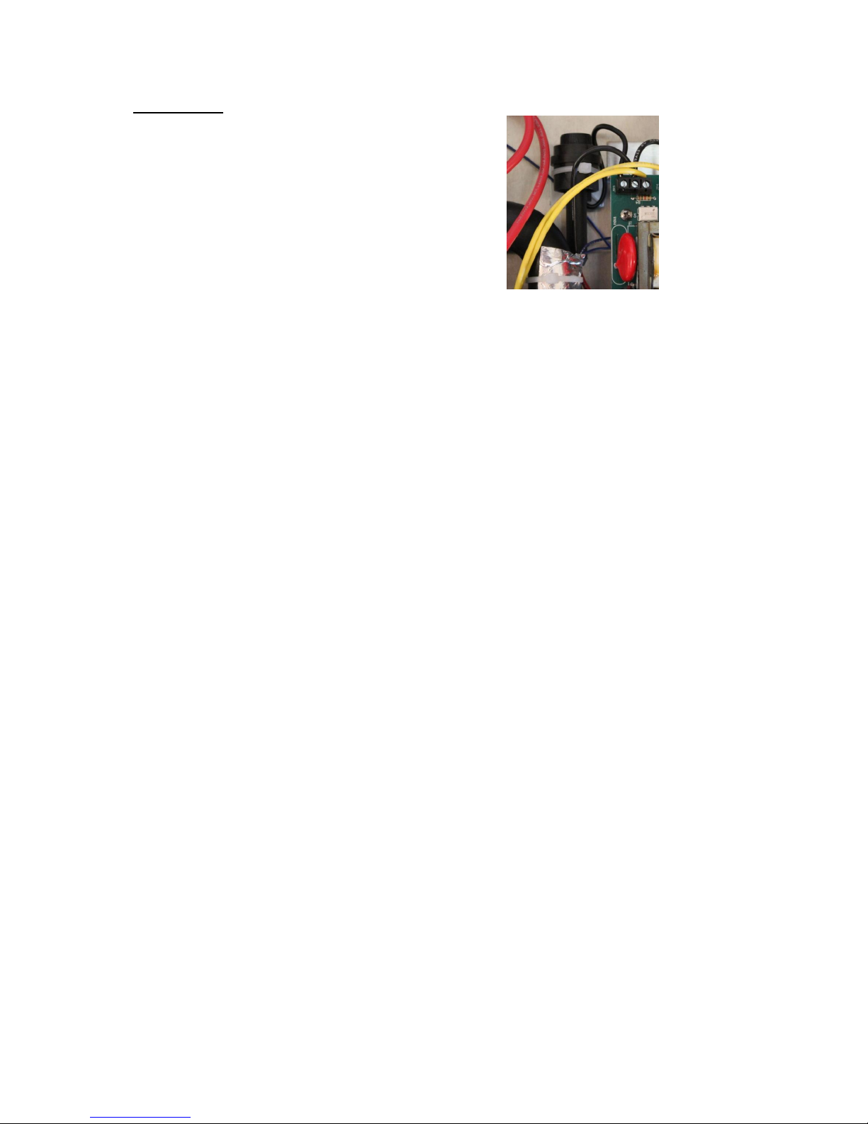
Control Fuse:
Disconnect power.
Remove cover.
Twist fuse and pull from fuse holder.
Insert new fuse in holder and twist to lock in place.
Reinstall cover.
Turn on power.
Page 31
31
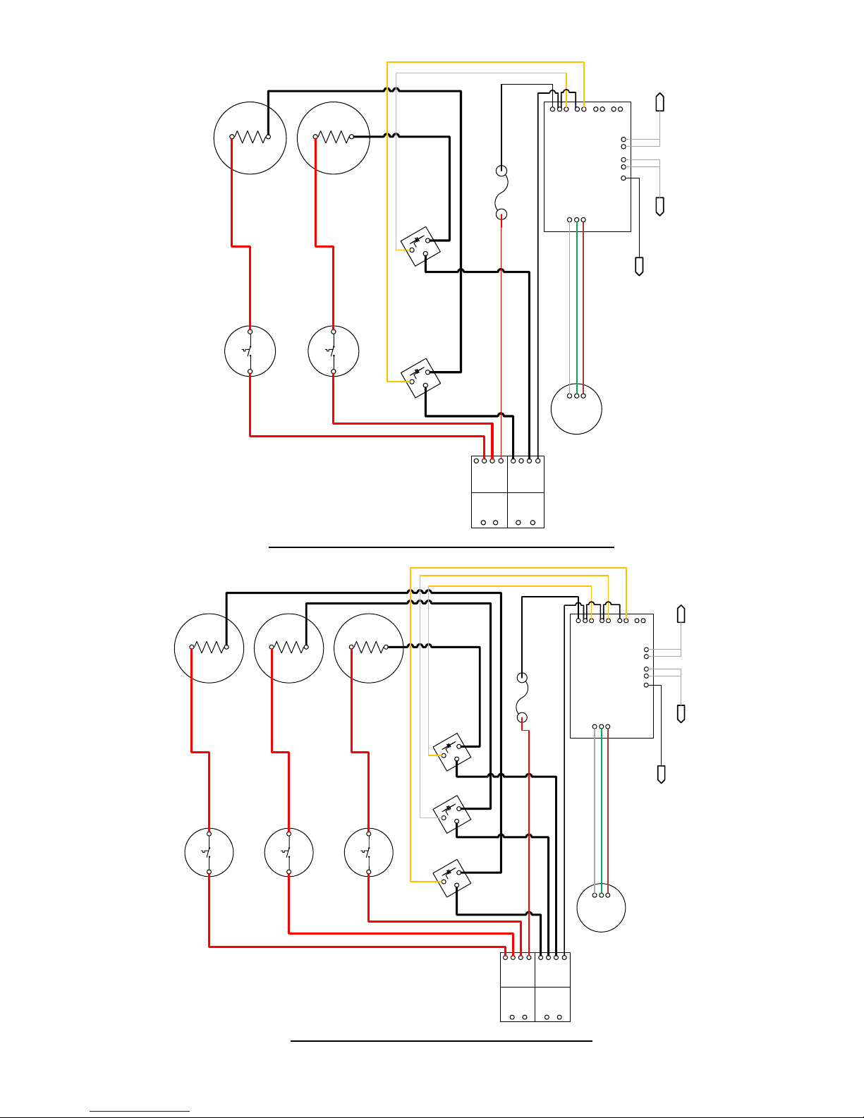
Wiring Diagram – Models 110-2, 145-2, 165-2, 180-2
Wiring Diagram – Models 220-3, 240-3, 280-3
Triac
Triac
Flow
Meter
Power
Distribution
Block
Temperature
Controller
Hi-Limit
Hi-Limit
Heating
Element
Heating
Element
Outlet
Thermistor
Inlet
Thermistor
Leak
Detection
Wire
Fuse
Triac
Triac
Triac
Flow
Meter
Power
Distribution
Block
Temperature
Controller
Hi-Limit
Hi-Limit
Hi-Limit
Heating
Element
Heating
Element
Heating
Element
Outlet
Thermistor
Inlet
Thermistor
Leak
Detection
Wire
Fuse
Page 32
32
SECTION VII – PARTS LIST
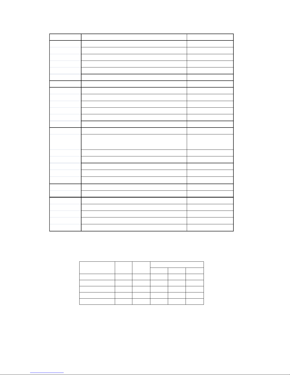
Element Resistance Chart
Element P/N
Watts
Volts
Ohms
Min.
Nom.
Max.
N1315-4500
4500
240
12.16
12.80
13.44
N1315-5500
5000
240
10.94
11.52
12.10
N1315-7000
7000
240
7.82
8.23
8.64
N1375-8000
8000
240
6.84
7.20
7.56
N1375-9000
9000
240
6.08
6.40
6.72
Category Description Hubbell P/N
Plumbing Quick-Connect -Inlet, 3/4" C x 3/4" MNPT LF4501B-1412
Quick-Connect-Outlet 3/4" C x 3/4" C LF4515B-14
Heating Chamber: 2 Element TK2-FM
Heating Chamber: 3 Element TK3-FM
Bell Coupling 3/4" FNPT x 1/2" FNPT COUPBELL 1/2" TO 3/4"
Filter Screen for Inlet SCREEN TK
Triac Triac (Supplied with wire leads) TG40E60
Elements 4500 Watts, 8.5" long N1315-4500
(with O-ring) 5500 Watts, 8.5" long N1315-5500
7000 Watts, 12" long N1315-7000
8000 Watts, 12" long N1375-8000
9000 Watts, 12" long N1375-9000
Extra O-Ring O RING SGB
Electrical Thermistor (Supplied with wire leads) USP9509
Auto Resetting Hi-Limit 140oF
(Supplied with wire leads)
L60
Temperature Control Board TK2000
Digital Display TKD2000
Power Distribution Block: 2 Pole 67512
Flow Meter (1/2" NPT, 0.2-8 GPM)
TK FLOW BR
Control Fuse
LGR-3
Wire Wire #18 (Specify COLOR: Yellow, Red, Black) WIRE 18 "COLOR"
Wire #10 (Specify COLOR: Red, Black) WIRE 10 "COLOR"
Miscellaneous Front Metal Cover for 2 Element Models TK100 COVER
Metal Base for Model 2 Element Models TK100 BACK
Front Metal Cover for 3 Element Models TK200 COVER
Metal Base for Model 3 Element Models TK200 BACK
Overlay cover for TKD2000
TANKLESS OVERLAY
U134
U016
Page 33

33
SECTION VIII – WARRANTY
MANUFACTURER’S LIMITED WARRANTY
1. PRODUCT WARRANTY: Hubbell warrants to the original purchaser at the original
address or the authorized transferee of such purchaser (collectively, the “Buyer”) the
Hubbell Tankless Water Heater and its components as manufactured by Hubbell (the
"Product") to be free from defects in materials and workmanship, under normal use and
service for the period of time identified below beginning from the date of installation,
provided that the Product is (i) installed within sixty (60) days from date of shipment from
Hubbell and (ii) installed by a licensed electrician and plumber (specific proof required) and
maintained in accordance with Hubbell's written instructions. In order for the Product
warranty to become effective, the original purchaser must submit via fax, mail or website the
Warranty Registration included in the Operating and Maintenance Manual supplied with
each new Product.
HEATING CHAMBER:
ELECTRICAL COMPONENTS:
REPLACEMENT PARTS:
REFURBISHED HEATERS:
Five (5) years
One (1) year
Thirty (30) days
One (1) year heating chamber and electrical
components
SUCH WARRANTIES DO NOT COVER:
Product failure caused by liming, sediment buildup, chemical corrosion,
chlorine/chloride corrosion, or freezing.
Product failure caused by the failure to remove air from system prior to or during
operation.
Product misuse, tampering or misapplication, accidental damage, improper installation
or the application of improper voltage.
Costs incurred for shipping, delivery, handling, and/or administrative charges.
Product failure due to lightening, flood or other natural or manmade calamities.
Labor charges of any kind.
THE FOREGOING WARRANTIES ARE EXCLUSIVE AND IN LIEU OF ANY OTHER
WARRANTY, EXPRESSED OR IMPLIED, INCLUDING BUT NOT LIMITED TO ANY
IMPLIED WARRANTY OF MERCHANTABILITY OR FITNESS FOR A PARTICULAR
PURPOSE OR PATENT OR OTHER INTELLECTUAL PROPERTY RIGHT
INFRINGEMENT.
Warranty Transfer Information: The warranty may be transferred to one (1) subsequent
homeowner at the same physical address upon payment to Hubbell of a $75.00 U.S. dollar
transfer fee. Said transfer fee and second owner information must be submitted by Certified
Mail within 7 days of the house sale closing or there will be no further warranty extended
under any circumstances. Failure of original owner to provide 2nd owner with information in
a timely fashion will not alter the requirements of this paragraph.
2. LIMITATION OF REMEDIES AND DAMAGES: Hubbell's liability and Buyer's
exclusive remedy hereunder will be limited solely, at Hubbell's option, to repair or
replacement by the Hubbell Service Center with respect to any claim made within the
applicable warranty period referred to above. Without limiting the generality of the
foregoing, all warranty items shall be returned by Buyer, at its sole expense, to the Hubbell
Service Center for replacement or repair. Hubbell reserves the right to accept or reject any
such claim in whole or in part. Hubbell will not accept the return of any product without
prior written approval from Hubbell, and all such approved returns shall be made at Buyer's
sole expense. HUBBELL WILL NOT BE LIABLE, UNDER ANY CIRCUMSTANCES,
FOR CONSEQUENTIAL OR INCIDENTAL DAMAGES, INCLUDING BUT NOT
Page 34

34
LIMITED TO LABOR COSTS OR LOST PROFITS RESULTING FROM THE USE OF
(OR INABILITY TO USE) THE PRODUCTS OR FROM THE PRODUCTS BEING
INCORPORATED IN OR BECOMING A COMPONENT OF ANY OTHER PRODUCT
OR GOODS.
WARRANTY REGISTRATION
3. WARRANTY REGISTRATION: To be covered under the Hubbell Manufacturer’s
Limited Warranty you must register your product within 30 calendar days of delivery.
Warranty registration using the form below may be submitted via mail to Hubbell Electric
Heater Co., P.O. Box 288, Stratford, CT 06615-0288, or via fax 203-378-3593, or via the
link on the website for Warranty Registration, www.buytankless.com/warranty. THIS IS A
LIMITED MANUFACTURER’S WARRANTY THAT CONVEYS BENEFITS TO THE
ORIGINAL PURCHASER, SUBJECT TO THE TERMS AND CONDITIONS SET
FORTH HEREIN. Keep your Product documents in a safe and secure location. Your
obligation under the terms of purchase and sale require that you must return your warranty
card within the prescribed timeframe (within 30 calendar days) and retain all proof of
purchase, installer receipts for your warranty in order to protect your rights and obtain
Manufacturer’s Limited Warranty benefits. The warranty resides with the Buyer with proof
of purchase not simply with an individual in possession of a Product. If the heater is to be
installed in new construction at a date later than 30 days from the date of delivery, send
further information when known so we may update your warranty record.
Product Information:
Model No.: ___________________ Serial No.: _____________________________
Purchaser’s Information:
Name of Purchaser: _____________________________________________________
Installation Address: _____________________________________________________
City: _______________ State: _____ Zip: _______ Date of Purchase: _____________
Electrician Information: Plumber Information:
Name: ________________________ Name: __________________________
Company: _____________________ Company: _______________________
Telephone: ____________________ Telephone: ______________________
License #: _____________________ License #: _______________________
4. FURTHER LIMITATIONS AND EXCLUSIONS AFFECTING YOUR
WARRANTY: This warranty is void if the product is not installed in accordance with
relevant, local electrical and plumbing codes and in accordance with the installation
instructions specified by the manufacturer. Local codes will override manufacturer’s
instructions at the time of installation and if additional installation parts are required, the
costs will be the responsibility of Buyer. Product nameplate identifying the model and serial
number must be affixed to the unit and legible for the warranty to be exercised. Product
without the nameplate is excluded from warranty consideration. Above ground level
installations must be protected with drip pans and drains just as the codes call for protective
requirements used in regular hot water tank installations. Buyer hereby accepts the entire
responsibility for ascertaining whether they have sufficient electrical power at their
residence to operate our Tankless Water heaters as indicated in our specifications which are
Page 35

35
readily available at our website, in our brochures and contained in the shipping box for
installers to read before installation. If Buyer has purchased without first ascertaining the
cost for installation or the necessary power available for operation, Hubbell at its sole and
complete discretion may allow a return and grant a refund less freight and less 30% of the
retail price as a restocking fee. The refund will be conditioned upon a determination by
Hubbell after inspection of the Product being returned (either unopened or in the original
shipping box and packing) that the Product has not been damaged. This request and for this
reason only must be made within 30 calendar days of receipt of the Product.
AFTER 30 CALENDAR DAYS FROM DATE OF PURCHASE THERE WILL BE NO
RETURNS WHATSOEVER. BUYER ACCEPTS ALL SALES AS FINAL. ANY
ALTERATION TO THE PRODUCT VOIDS ALL WARRANTIES. HUBBELL IS NOT
RESPONSIBLE FOR ANY OTHER CHARGE OR EXPENSE INCURRED OTHER
THAN THE ORIGINAL PURCHASE PRICE OF THE PRODUCT. Hubbell shall not be
liable for consequential, special, incidental or contingent expenses or damages arising
directly or indirectly from any defect in or use of the Product nor will Hubbell be liable for
any water damage arising directly or indirectly from the use of the Product or from the
failure of or defect in any component part or connecting plumbing. Hubbell and Buyer agree
to these and the above terms in their entirety and accept all sales as final without recourse to
a credit card company and hereby agree that this Manufacturer's Limited Warranty shall be
governed by the laws of the State of Connecticut any and all actions arising from or relating
to this Manufacturer’s Limited Warranty and any aspects of the Product shall be brought in a
court of competent jurisdiction in Fairfield County, Connecticut.
WARRANTY PROCEDURE
5. PARTS REPLACEMENT PROCEDURE (Under Warranty within 3 Years): Have
your licensed electrician determine the exact parts that are defective and require
replacement. Please note that technical support is available for qualified technicians only
(licensed electricians and/or plumbers). Technical support that involves potentially
dangerous electrical conditions is not available to an unqualified person.
When contacting Hubbell, please be sure that the technician has the following information
on hand:
Copy of your original Warranty Registration.
Be sure that the technician has read the “Operation and Maintenance Manual” and has
written down all the data from the Advanced Troubleshooting Section.
If, at the sole discretion of Hubbell, a component requires repair or replacement under the
terms of this Manufacturer’s Limited Warranty, the part must be purchased and paid for
under our “Bill and Credit” terms and will be shipped via standard ground delivery. All
shipping charges are not included and are the responsibility of the Buyer. If faster shipping
service is desired, the Buyer must select and pay for same.
The replacement part purchased under our “Bill and Credit” terms is purchased via credit
card and upon return of the defective parts Hubbell will determine the cause of failure, and if
under warranty will issue a full credit less shipping charges. The returned part must be
received by Hubbell within thirty (30) days of shipment of the replacement part. Hubbell
will evaluate the returned part within ten (10) days, and if determined to be defective and
covered under terms of this warranty, full credit for the part will be issued.
Return warranty parts to: Hubbell Electric Heater
ATTN: Tankless Warranty
45 Seymour Street
Stratford, CT 06615
Page 36
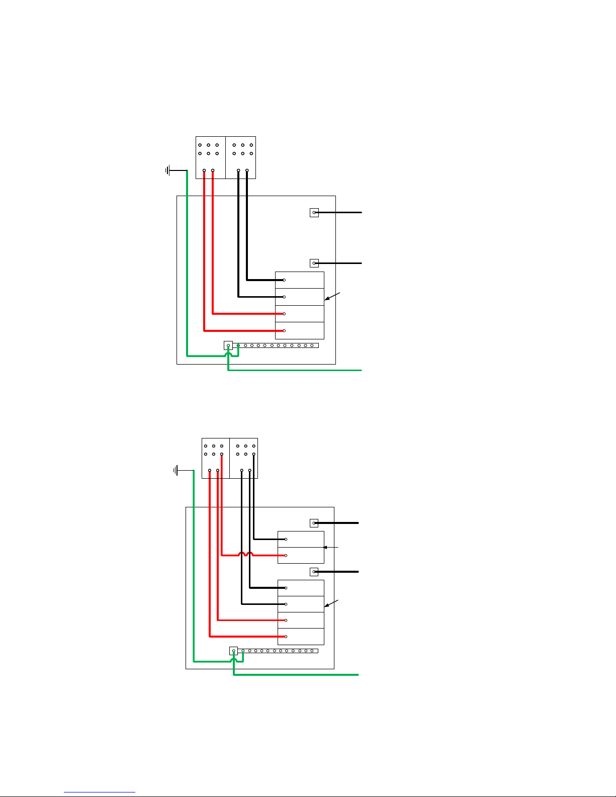
36
APPENDIX I – SUB-PANEL WIRING DETAILS
Refer to the following wiring details when your new Hubbell Tankless Water Heater is to
replace an existing tankless water heater that utilizes a sub-panel with circuit breakers and
you are keeping the existing sub-panel.
2-Element Diagram
3-Element Diagram
L1 from Main Panel
Sub-Panel
Ground from Main Panel
Quad Breaker
The two inner poles are
one breaker. The two outer
poles is another breaker.
Breaker 1
Breaker 2
Breaker 2
Breaker 1
Black
Black
Red
Red
Green
Power Distribution Block
L2 from Main Panel
Power Distribution Block
L1 from Main Panel
Sub-Panel
Ground from Main Panel
Double Pole Breaker
Quad Breaker
The two inner poles are
one breaker. The two outer
poles is another breaker.
Breaker 1
Breaker 1
Breaker 2
Breaker 3
Breaker 3
Breaker 2
Black
Red
Black
Black
Red
Red
Green
L2 from Main Panel
Page 37

37
NOTES
Page 38

38
NOTES
Page 39

39
NOTES
Page 40

40
P.O. BOX 288
STRATFORD, CT 06615-0288
PHONE: (877) 649-8589
FAX: (203) 378-3593
INTERNET: http://www.buytankless.com
 Loading...