

Page 1
Marine Products Division
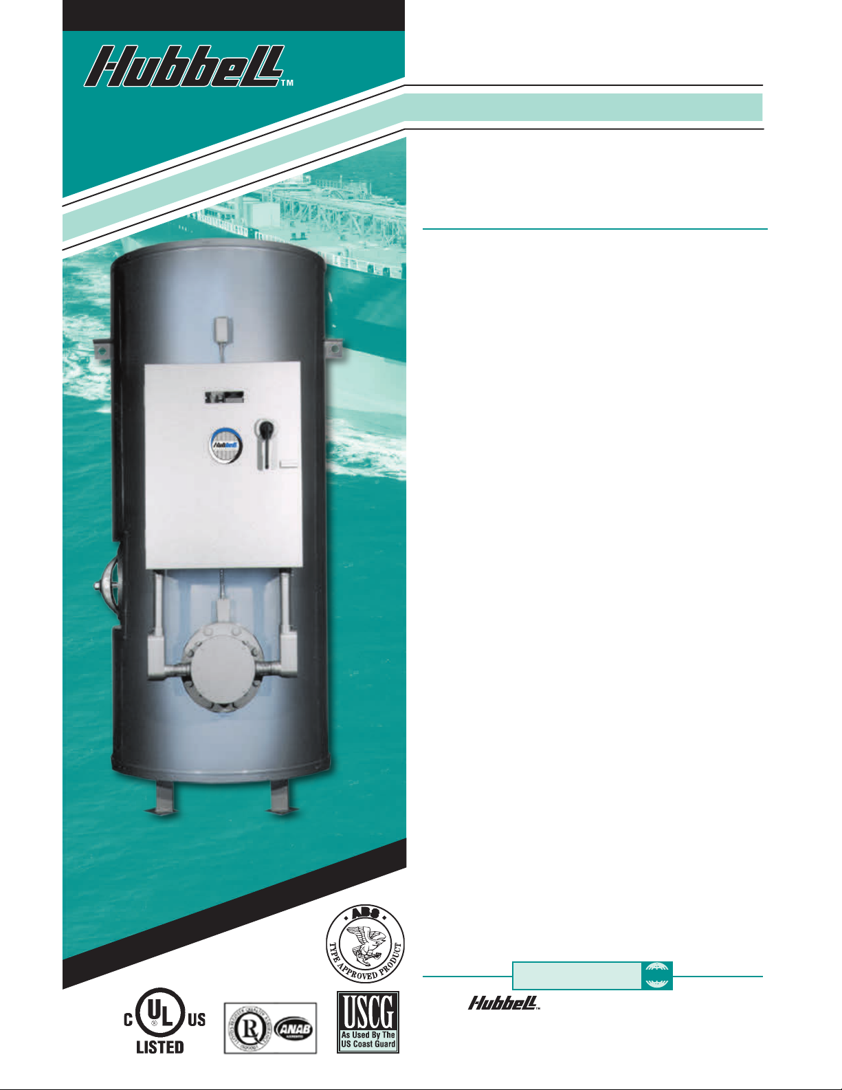
Model MSH & MH
Shipboard Electric
Water Heater
80-5000 Gallon Capacity
15-1600 KW — All Voltages & Phases
The MSH is a storage
packaged water heater for
marine use.
Reliable
■
Only high grade materials
used in construction to
ensure long operating life
■
Hydrastone cement
lining provides superior
protection and tank
longevity
■
Heavy duty construction
withstands demanding
marine use
Marine Approvals
■
United States Coast Guard
(USCG) conformance
and Type Approved by
American Bureau of
Shipping (ABS)
■
USCG conformance
and ABS Type Approval
eliminates costly delays
and uncertainties during
ship inspection
Mounting Systems
■
Heavy-duty legs secure
the tank to deck
■
Side-sway bulkhead
attachment points provide
added mounting stability
■
The entire mounting
system is integrally welded
to tank for maximum
stability and safety
Packaged System
■
Fully packaged water
heater saves time and
money during installation
■
All electrical operating
controls are factory
selected and wired to
ensure reliable operation
■
Full range of styles, sizes,
and optional features to
meet your exact water
heating needs
A Heavy Duty Storage Electric Water
Heater For Marine Use
The Hubbell Model MSH and MH water heater is specically
designed for marine use on board a surface vessel or platform
and is in USCG conformance and is ABS Type Approved. By
utilizing deck and bulkhead mounting supports, the water
heater is securely fastened to the ship structure, thus providing
a secure and reliable water heater installation. The heavy-duty
carbon steel storage tank is lined with specially formulated
hydrastone cement that provides superior protection, tank
longevity and withstands demanding marine use.
When you specify and install a Hubbell model MSH or MH,
knowing that it is in conformance with USCG regulations and
is ABS Type Approved, you will have condence that the ship
owner will be provided with a quality product that is a long
lasting and trouble free source for hot water.
ISO 9001:2008
The Electric Heater Company
P.O. Box 288 ■ Stratford, CT 06615-0288
Phone: 203-378-2659
E-mail: info@hubbellheaters.com
ISO
■
FAX: 203-378-3593
■
www.hubbellheaters.com
Page 2
Cement Lined Tanks
Provide Longer
Service Life
NO
NO
GLASS
GLASS
LINING
LINING
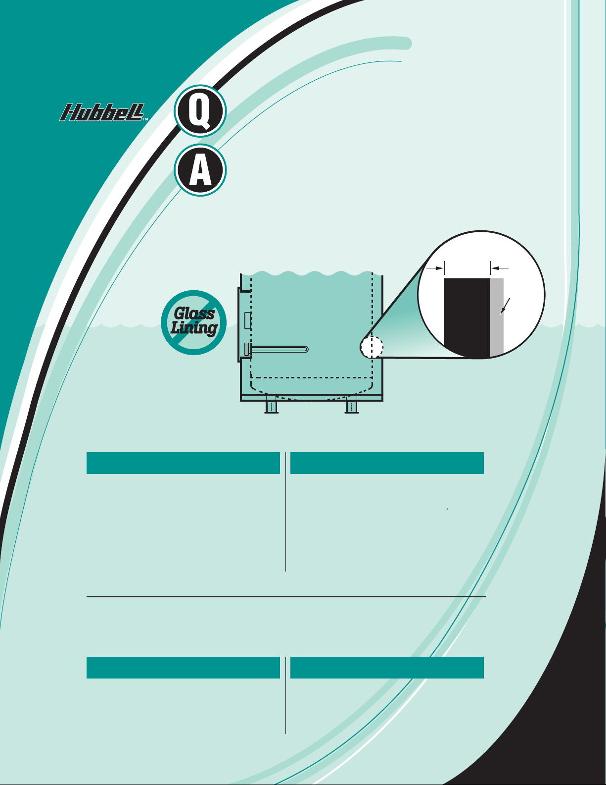
What is the most common reason
why a water heater fails?
Failure of a tank’s protective lining allows
water to come into direct contact with the
steel tank causing it to corrode and leak.
Therefore, the type of protective lining is
the single most important feature when
determining the quality of any water heater.
The ability of a lining to protect the steel tank
is primarily based upon its thickness and
complete coverage of all steel surfaces.
Tank Cross Section
5
/8"
Hydrastone
Cement
Lining
Steel
Pressure
Vessel
Linings Available For A Steel Tank
Cement Lining
A specially formulated Hydrastone cement
applied to a minimum of
surfaces. The cement lining covers 100% of
all interior surfaces and is 125 times thicker
than glass lining. Due to the thickness and
guaranteed coverage of cement lining there is
no need for a sacricial anode. An extremely
durable and long lasting lining suitable for
hot and cold potable water storage in marine
applications.
5
/8" thickness on all
Phenolic Lining
An epoxy coating applied in 2 coats to a total
of 10-12 mils DFT. Typically used in process
applications using low conductivity D
or food grade water.
I, distilled
Non-Ferrous Tanks
A solid Non-Ferrous tank does not require a lining because the pressure vessel itself is
constructed from material which is impervious to the corrosive eects of hot water. This type of tank
will provide a signicantly longer service life than all lined steel tanks, but is initially more costly.
90/10 Copper-Nickel
A 90% Copper 10% Nickel alloy provides
excellent strength and corrosion resistance.
Typically used in applications with corrosive
environments (salt water) or in critical marine
applications requiring long tank life.
Stainless Steel
Stainless Steel (Specify: Type 304, 316, or
316L) is suited for applications requiring a
corrosion resistant tank with minimal leaching
of impurities into the water. Well suited for
process, RO and D
I water systems.
Note: Unlined non-ferrous tanks do not require a manway. Inspection openings will be provided as required.
2
2
Page 3
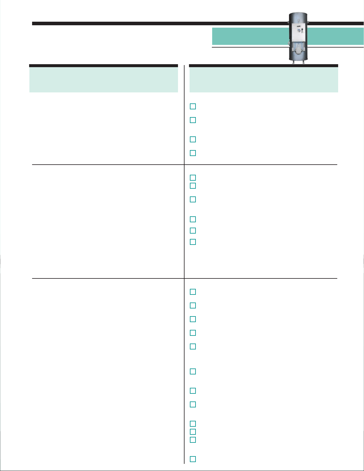
Model MSH & MH
Shipboard Electric
Water Heater
Model MSH and MH
Standard Equipment
Vessel Construction
1. All welded carbon steel vessel designed and built in
strict accordance with the ASME Code Section IV and
stamped, certied and registered with the National Board
of Boiler and Pressure Vessel Inspectors.
2. All internal tank surfaces are lined with a minimum of
thick Hydrastone cement for superior protection and tank
longevity.
3. Designed for 100 psi working pressure and hydrostatically
tested at 150 psi (1 1/2 times the WP).
General
1. Heavy duty 2" thick berglass blanket insulation covers
the pressure vessel for maximum operating eciency and
minimal standby heat loss.
2. Heavy gauge galvanized steel protective jacket holds
insulation in place and protected to ensure highly ecient
operation.
3. Integrally welded bulkhead attachment points.
4. Entire vessel is supported on heavy duty integrally welded
steel supports for sturdy deck mounting.
5. Full ve (5) year Non Pro-Rated tank warranty and one (1)
year electrical component warranty.
6. Bronze ASME rated combination temperature and
pressure safety relief valve set at the vessel working
pressure and 210ºF.
7. ABS Type Approved and in conformance with USCG
regulations.
5
/8"
Model MSH and MH
Optional Equipment
Vessel
1A. Alternate protective lining:
Phenolic epoxy resin.
1B. Alternate vessel construction:
Stainless Steel (Please specify Type: 304, 316 or 316L)
90/10 Copper-Nickel, other.
1C. Alternate working pressure:
Please specify
1D. Alternate tank design:
ASME stamped to Section I or VIII
General
1. Skid mounting on heavy duty all welded I Beam
2. Type 304 stainless steel protective jacket,
please specify if painted.
. Dual energy package provides operational exibility
3
for electric and steam or boiler
See page 8 for details.
. Manway 12" x 16" size
4
. Inspection opening 3" NPT
5
. Specic third party approval including BV, NR-13,
6
Lloyds or MIL spec.
water power.
Electrical Operating Controls
1. All electrical operating controls are factory sized,
selected, wired, tested, and mounted in a NEMA 1
enclosure to ensure safe and reliable operation.
2. A power distribution block is supplied for single point
electrical installation.
3. Power fuses rated at a maximum of 60 Amps protect
each heating element branch circuit per NEC and UL
requirements. Each branch circuit has a maximum rating
of 48 Amps.
4. Heavy duty denite purpose magnetic contactor with
integrally mounted power fuse block assembly switches
power on/o to each branch circuit.
5. Heavy duty removable ange type immersion heating
element provides long service life.
6. Fully adjustable thermostat maintains accurate water
temperature and is sized by the factory to control the
appropriate number of heating element circuits.
7. A generously sized transformer provides fused 120V to
the control circuit
8. A fully adjustable (100-240 ºF) safety hi-limit device with
manual reset interrupts power to the control circuit in the
event of over-temperature water in the storage tank.
9. Safety door interlock mechanism interrupts power to the
control circuit upon opening the electrical control panel.
10. Louvers in the control panel allow for cooling of the
electrical components to ensure maximum electrical
component longevity (when required).
Electrical
1. NEMA 4 weather resistant enclosure for outdoor/wet
locations.
2. Explosion resistant enclosure for hazardous locations.
Please specify class, division, and group.
3. Built-in circuit breaker (with or without shunt trip) or a
built-in non-fused On/O disconnect switch.
4. Alternate element sheath material (Please specify:
Incoloy, Stainless Steel, other).
5. Specialized heating element construction including:
Special watt density rating, passivation, electropolishing,
hermetic seals or any other feature required to meet the
needs of your application.
6. Factory installed low water cut out device to disengage
electrically the heating element(s) in the event of
insucient water in the tank.
7. Dial thermometer and pressure gauge factory installed in
the tank.
8. Intra-tank circulation pump package with On/O switch to
continuously circulate water within the tank and thereby
reduce stratication.
9. Status indicating lamp(s).
10. Audible alarm system.
11. Digital display electronic temperature controller. Please
specify with or without RS485 communication port for
remote operation of the temperature controller.
12. Additional ground connections
3
Page 4
Marine Products Division
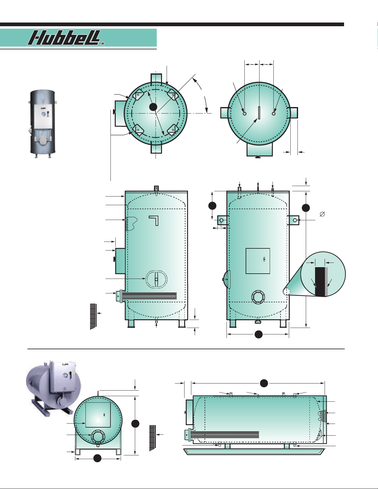
Outline Dimensions
Model MSH (vertical)
Storage Tank
Protective Jacket
Hot Water Outlet
o
45
6" 6"
T&P Relief Valve
Mounting Hole
4 Places Equally
Spaced 90° Apart.
Tanks 26" diameter
and smaller 4" x 4" x
1
/4" Base Pads with 5/8"
mounting hole
Tanks 30" - 42" dia.
5” x 5” x 1/4" Base Pads
with9/16" mounting hole.
Tanks 48" diameter
and larger 6" x 6" x 1/4"
Base Pads with 9/16"
mounting hole.
Protective Jacket
Pressure Vessel
Insulation
Electric Control Panel
12" x 16" Manway
(when required)
Electric Heating
Element
10"
G
Base View
F
1 1/2"
Lifting
Lug
Hot Water
Outlet
Top View
Lifting
T&P Relief
Lug
Valve
3 1/4"
4"
B
Cement
Lining
7/8"
Bulkhead
Mounting Holes
2 Places
Tank Cross
Section
Hydrastone
5
/8"
Steel
Pressure
Vessel
Model MH (horizontal)
Electric Control
Electric Heating
Supports (Specify
Saddles Or Skids)
4
Panel
Element
D
Front View
Withdrawal
Space
6"
Combination Cold
Water Inlet And Drain
Side View Front View
4"
E
10"
Withdrawal
Space
Cold
Water
Inlet
Lifting
Lugs
T&P Relief
Valve
Side View
(Note: optional skid base shown)
A
C
Hot Water
Outlet
Pressure
Vessel
Insulation
Protective
Jacket
12" x 16"
Manyway
(when required)
Drain
Page 5

Model MSH & MH
Shipboard Electric
Water Heater
Dimensional Data, Model MSH & MH
Overall Dimensions (Inches)
Storage
Capacity
(Gallons)
80 26
120 28
150 30
175 34 73 67 34 40 20 24 30 x 63 1½ 1500
200 34 82 76 34 40 20 24 30 x 72 1½ 1700
225 34 89 83 34 40 20 24 30 x 79 1½ 17 50
250 40 74 68 40 46 20 30 36 x 64 1½ 1850
275 40 80 74 40 46 20 30 36 x 70 1½ 2000
300 40 88 82 40 46 20 30 36 x 78 1½ 2180
325 40 92 86 40 46 20 30 36 x 82 1½ 2300
350 40 94 88 40 46 20 30 36 x 84 1½ 2500
375 46 81 75 46 52 22 36 42 x 71 1½ 2600
400 46 85 79 46 52 22 36 42 x 75 1½ 2700
425 46 88 82 46 52 22 36 42 x 78 1½ 2900
450 46 93 87 46 52 22 36 42 x 83 1½ 3000
475 52 79 73 52 58 24 42 48 x 69 2 3100
500 52 82 76 52 58 24 42 48 x 72 2 3225
525 52 85 79 52 58 24 42 48 x 75 2 3350
550 52 89 83 52 58 24 42 48 x 79 2 3400
575 52 93 87 52 58 24 42 48 x 83 2 3500
600 52 95 89 52 58 24 42 48 x 85 2 3650
700 52 107 101 52 58 24 42 48 x 97 2 4000
800 52 119 113 52 58 24 42 48 x 109 2 4300
900 52 132 126 52 58 24 42 48 x 122 2 4800
1000 52 145 139 52 58 24 42 48 x 135 2 5200
1250 58 14 9 14 3 58 64 26 48 54 x 139 2 5600
150 0 58 174 168 58 64 26 48 54 x 164 2 6000
175 0 64 168 162 64 70 28 54 60 x 158 3 74 0 0
2000 64 185 179 64 70 28 54 60 x 175 3 8100
2500 76 169 163 76 82 32 60 72 x 159 3 8200
3000 76 197 191 76 82 32 60 72 x 187 3 8300
3500 88 174 168 88 94 36 72 84 x 164 6 FLG. 8900
4000 88 195 189 88 94 36 72 84 x 185 6 FLG. 9800
4500 N/A N/A 178 94 100 40 84 90 x 174 6 FLG. 10700
5000 N/A N/A 200 94 100 40 84 90 x 196 6 FLG. 1160 0
Vertical
Diameter
A
HeightBLength
C
64
72
78
60 26 32 15 18 22 x 54 1½ 1000
71 28 34 15 18
75 30 36 20 20 26 x 68 1½ 130 0
Width
D
Height
E
Bulkhead
Mounting
F
Bolt
Circle
G
Storage
Tan k
Diameter
x Length
24 x 62
Inlet
Outlet
Sizing
(NPT)
1½ 1150
Approx.
Shipping
Weight
(Lbs.)
Note: All dimensions are approximate and subject to change. Please reference the submittal drawing for actual dimensions.
The tank selections above are shown for convenience. A full selection of storage capacities are available by entering the desired
capacity into the model number.
* 80, 120 and 150 gallon tanks do not come equipped with a manway. Please consult factory if desired on these sizes.
5
Page 6

Marine Products Division
Recovery Ratings And Amperage At Selected KW
KW
INPUT
15
20
25
30
35
40
45
50
55
60
65
70
75
80
85
90
95
100
110
120
125
150
175
200
225
250
275
300
325
350
375
400
450
500
1000
1200
1400
1600
BTU/HR
RATING
51,180 102 77 61 51 44 42 36 23 20 18
68,240 136 102 82 68 58 56 48 30 26 24
85,300 170 128 102 85 73 69 60 38 33 30
102,360 205 153 123 102 88 83 72 46 39 36
119,420 239 179 143 119 102 97 84 53 46 42
136,480 273 205 164 136 117 111 96 61 53 48
153,540 307 230 184 153 131 125 108 68 59 54
170,600 341 256 205 170 146 139 120 76 66 60
187,660 375 281 225 187 161 153 132 84 72 66
204,720 409 307 245 205 175 167 145 91 79 72
221,780 443 332 266 222 190 181 157 99 85 78
238,840 477 358 286 239 205 195 169 106 92 84
255,900 511 383 307 256 219 208 181 114 99 90
272,960 545 409 327 273 234 222 193 122 105 96
290,020 580 435 348 290 248 236 205 129 112 102
307,080 614 460 368 307 263 250 217 137 118 108
324,140 648 486 389 324 278 264 229 145 125 114
341,200 682 511 409 341 292 278 241 152 131 120
375,320 750 562 450 375 321 306 265 167 145 132
409,440 818 614 491 409 351 333 289 183 158 145
426,500 852 639 511 426 365 347 301 190 164 151
511,800 1023 767 614 511 438 417 361 228 197 181
597,100 1193 895 716 597 511 486 421 266 230 211
682,400 1364 1023 818 682 584 556 482 304 263 241
767,700 1534 1150 920 767 657 625 542 342 296 271
853,000 1705 1278 1023 852 730 695 602 380 328 301
938,300 1875 1406 1125 937 803 764 662 418 361 331
1,023,600 2046 1534 1227 1023 876 834 723 456 394 361
1,108,900 2216 1662 1329 1108 950 903 783 494 427 391
1,194,200 2386 1790 1432 1193 1023 973 843 532 460 421
1,279,500 2557 1917 1534 1278 1096 1042 903 570 493 452
1,364,800 2727 2045 1636 1363 1169 1112 963 608 525 482
1,535,400 3068 2301 1841 1534 1315 1251 1084 685 591 542
1,706,000 3409
3,412,000 6819 5113 4090 3409 2922 2779 2408 1521 1314 1204
4,094,400 8182 6135 4908 4090 3506 3335 2890 1825 1576 1445
4,776,800 9546 7158 5726 4772 4090 3891 3372 2130 1839 1686
5,459,200 10910 8181 6544 5454 4675 4446 3854 2434 2102 1927
60 °F
Gallons Per Hour (GPH) Heated At
Various Temperature Rises
Δ 80 °F Δ 100 °F Δ 120 °F Δ 140 °F Δ
2556 2045 1704 1461 1390 1204 761 657 602
208V 3F 240V 3F 380V 3F 440V 3F 480V 3F
Amperage Rating At Various Voltages
Notes: The KW selections above are shown for convenience. A full selection of KW ratings from 1 to 1600 KW is available by entering the
desired KW into the model number. For alternate voltages including 415, 575 and 600 volt, please consult factory.
Electrical
Note: Each branch
circuit is rated at
a maximum of 48
Amps and each
circuit is typically
operated as an
independent
temperature step.
6
KW x 1000
Volts
KW x 1000
Volts
÷ 1.73 = Amps 3 Φ
= Amps 1
Φ
Example: 150 KW at 480V 3Φ
150 x 1000
480
180 ÷ 48 Amps max circuit rating = 3.75
Round up the number of circuits to 4
÷ 1.73 = 180 Total Amp Draw
Page 7

Model MSH & MH
Shipboard Electric
Water Heater
Model MSH & MH Sizing Information
Step 1: Solve for the unknown using the formulas stated below
Variables To Solve For:
KW Requirement: GPH x °F ∆T x 0.00244 = KW
Temperature Rise: KW x 410 ÷ GPH = °F ∆T
Flow Rate: KW x 410 ÷ °F ∆T= GPH
Metric Conversions
Liters x 0.2641 = Gallons
Gallons x 3.79 = Liters
Gallons x 0.003785 = m
m3 x 264.2 = Gallons
1
°C ∆T = 1.8°F ∆T
°F = (°C x 1.8) + 32
°C = (°F - 32) x 0.556
Watts/Sq.Cm. x 6.4 =
3
Watts/Sq.In.
Watts/Sq.In. x 0.155 =
Watts/Sq.Cm.
psi x 0.06896 = Bar
Bar x 14.5 = psi
psi x 6.86 = kPa
kPa x 0.1456 = psi
Kg/cm2 x 14.28 = psi
psi x 0.07 = Kg/cm2
Lbs x 0.4536 = Kg
Kg x 2.2 = Lbs
Model Number Designation
— —
■
Step 1
Model:
MSH = Vertical
MH = Horizontal
■
Step 2
Storage Capacity:
80-5000 U.S. Gallons
Example: MSH250-0-80SLT5
A Hubbell marine vertical water heater with a storage
capacity of 250 gallons and an 80 KW electric heating
element. The tank is cement lined. Power required is 440
VAC, 3 phase, 60 Hz.
0
■
Step 3
Elec tric KW:
5-1600K W
■
Step 4
Ve s s e l Typ e:
SL = Hydrastone
Cement lined tank
GL = Phenolic Lined
Steel
CN = Solid 90/10
Copper-Nickel
SS = Solid Stainless
Steel (Specify Type
304 or 316L)
■
Step 5
Voltage / Phase / Hz:
RS = 208-1-60
R = 208-3-60
S = 240-1-60
T = 240-3-60
W = 277-1-60
T3 = 380-3-50/60
T7 = 415-3-50/60
T5 = 440-3-60
T4 = 480-3-60
T4S = 480-1-60
T6 = 600-3-60
Option Note
Any and all optional equipment for a water heater must be called
out in the written specication. A model number in and of itself
does not reect any optional equipment selected.
(Manufacturer reserves the right to change specications without notice.)
7
Page 8

Marine Products Division
Benet Of Dual Fuel Capability
The Hubbell model MSH and MH water heater is available
with a factory installed heat exchanger to provide heating
capability utilizing ships steam or boiler water. While the
ship is under way and the boilers are producing steam,
the water heater will operate in “primary” mode and use
steam to heat the water. When the ship is dockside, and
steam generation is reduced (or completely shut down), the
operator can switch the water heater over to electric heating
mode by simply turning a switch on the Hubbell control panel
which activates the factory packaged and installed electric
immersion heaters. This dual fuel capability provides ship
operators with complete exibility in determining which fuel
mode is most advantageous to operate at any given time.
Optional Steam Package
Electric
Control Panel
Electric
Heater
Steam Heating
Coil (steam
controls not
shown)
Standard Features
Steam / Boiler Water Heating Coil
1. A high quality factory installed 2 pass U-Tube heating
coil constructed from 18 BWG
copper tubing designed for a maximum working
pressure of 150 psi.
2. All wetted parts including the tube sheet and baes
are non-ferrous for maximum longevity.
3. Heavy duty fabricated steel head with threaded NPT
steam and condensate connections.
Steam Operating Controls
1. Steam operating controls are factory selected, sized,
piped and tested to ensure reliable operation.
2. All steam components are factory plumbed with
schedule 40 black iron pipe and ready for steam and
condensate connections.
3. High quality cast iron pilot operated steam control
valve modulates the ow of steam through the
heating coil to provide accurate water temperature
control.
4. Cast iron Y strainer with 20 Mesh screen protects the
steam controls and coil from dirt and debris in the
steam supply.
5. Thermostatic drip trap removes condensate from the
steam supply line.
6. Heavy duty cast iron oat and thermostatic main
condensate trap for optimum eciency.
7. Brass vacuum breaker and dial steam pressure
gauge installed in the heating coil head.
Note: Additional steam and boiler water design literature
is available in Hubbell brochures titled “ST”,“BW” and
“Heating Coils”.
3
/4" O.D. single wall
Optional Features
Optional vessel construction and optional general
construction features as shown on page 3.
Steam Heating Coil
1. Double wall tubing with a leak detection port
2. Alternate tubing material please specify:
(Stainless Steel, 90/10 Copper-Nickel, Other)
3. Fabricated steam head constructed from:
(Stainless Steel, Copper Alloy, Other)
Operating Controls
4. Steam controls are factory selected and sized, but
shipped loose for in the eld installation by others.
5. Various steam control valves are available to meet
the specic needs of your application, please
specify: Self-operated type, pneumatic operated,
electric motor operated, separate pressure
reducing pilot type.
6. Single solenoid safety system closes the control
valve should the water temperature in the tank
reach the hi-limit set point. Requires 120 volt 5
amp electrical service.
7. A double solenoid safety system dumps over
heated water in the storage tank to drain in
addition to closing the control valve. Requires 120
volt 5 amp electrical service.
8. Dial water thermometer and pressure gauge
factory installed in the tank.
9. Factory wrapped and baed steam coil with
integral pump package.
10. Steam Controls to be cast steel construction.
8
8
Page 9

Model MSH & MH
Model MSH & MH
Shipboard Electric
Optional Steam Package
Shipboard Electric
Water Heater
Water Heater
Steam Component General Conguration
The steam control valve maintains accurate water
temperature in a steam red water heater by regulating
the ow of steam through the heating coil.
Adjustable
Temperature Pilot
Steam Inlet
Y Strainer
Steam
Control
Valve
Thermostatic
Drip Trap
To sensing bulb
in tank
Pneumatic or electronic
controller (if required)
Steam Pressure Gauge
Vacuum Breaker
Steam Coil
Y Strainer
Condensate Outlet
There are four types of steam control valves available for
use on a steam red storage water heater.
Self Operating
The valve design includes a bulb and capillary assembly
charged with a thermally responsive vapor. The
expansion/contraction of the vapor acts upon the valve
bellows in order to control the ow of steam through
the valve. No external power source is required for
operation.
Pneumatically Operated
In this conguration the ships air supply feeds a factory
installed temperature controller which operates the
steam control valve. The temperature controller sends
a precise air signal to the steam control valve which
adjusts the ow of steam into the heating coil. The
temperature controller is fully adjustable from 50-250°F
and requires 20 psi air at a maximum consumption of
0.5 SCFM.
Pilot Operated
A pilot operated control valve is the most widely used
type of valve for standard water heating applications.
In this type of valve, a temperature pilot device utilizes
steam to operate the main valve. No external power
source is required other than steam. This is a highly
dependable temperature control system which is suitable
for most applications. As an option, this valve may
include a pressure reducing pilot which limits the steam
pressure to a predetermined maximum.
Electronic Operated
This control valve is similar to a pneumatically operated
system, except in this case the temperature controller is
a sophisticated digital display electronic device which
outputs a 4-20ma signal to a compact motor mounted
on the steam control valve in order to proportionally
control the ow of steam to the heating coil. The
temperature controller displays set point as well as
actual water temperature and is available with an RS485
communications port for remote control.
F & T Main
Condensate Trap
9
9
Page 10

Marine Products Division
Marine Products Division
Optional Steam Package
Heating Coil General Conguration
Length B
10
10
Inlet
Outlet
Head
Rib Gasket
Tub e
Sheet
Tank
Flange
Tank Tank LiningRing Gasket
Tube Support Tub es
Please Complete The Following Information:
Tube Sheet Data
1
Outside Diameter
Thickness
Material
Number of Tube holes
in the tube sheet
Does the tube sheet have
Bolt Holes in it?
If Yes:
■ # of bolt holes
■ Dia. of bolt holes
■ Bolt circle
Do the bolt holes straddle
the centerline?
Yes No
Diameter of the neck nozzle on the tank.
2
Outside Diameter
Inside Diameter
(Include thickness of neck lining, if any)
Circumference Of Neck
Immersion length
3
of tubes “B”
Heating surface area
in Sq. Ft. (if known)
Tank Type: Verti cal Horizontal
Tank dimensions: Diameter
Height
Pull space
maximum length
Yes No
Tube O u t s i d e
4
Diameter
Material
Gauge BWG
Typ e
Design Pressure
Design Temperature
Number of passes
5
Number of tube
6
supports
Distance to each
tube support
Material
O.D. of supports
Thickness
Recovery rated
7
to heat GPH
from oF to oF
When supplied with the following
heat source:
Lbs. / Hou r
Steam Consumption
from oF to oF
from oF to oF
Pressure Drop
8
Steam psi
Boiler or HTHW psi
Single Wall Double Wall
Full Half type
Steam at psig
Boiler Water at GPM
HTHW at GPM
Page 11

Optional Steam Package
Steam Consumption Formula
GPH x °F ∆T x 8.33
Model MSH & MH
Model MSH & MH
Shipboard Electric
Shipboard Electric
Water Heater
Water Heater
=
Latent Heat of Steam
Steam Pressure (psi)
Latent Heat
0 2 5 10 15 20 25 30 40 50
970 966 960 953 946 939 933 929 920 912
Dual Fuel Model Number Designation
— —
■
Step 1
Model:
MSH = Vertical
MH = Horizontal
Example: MSH400-ST-120SLT5
A Hubbell vertically installed 400 gallon dual fuel marine water heater with
a factory installed steam heating coil as the primary heating source and
a 120 KW electric heating element to operate as the secondary heating
source. Tank is cement lined. Power required is 440 VAC, 3 phase, 60 Hz.
Please note that steam heating capacity and construction features are not
identied in the model number and therefore must be noted in the written
specications.
■
Step 2
Storage Capacity:
80-5000 U.S. Gallons
■
Step 3
Primary
Heating:
ST = Steam
BW = Boiler
Water
O = No steam
■
Step 4
Secondary
Heating
Electric:
5-1600K W
■
Step 5
Tan k :
SL = Hydrastone
Cement lined tank
GL = Phenolic
Lined Steel
CN = Solid 90/10
Copper-Nickel
SS = Solid
Stainless Steel
(specify Type 304,
316 or 316L)
Lbs / Hr Steam
■
Step 6
Voltage / Phase / Hz:
RS = 208-1-60
R = 208-3-60
S = 240-1-60
T = 240-3-60
W = 277-1-60
T3 = 380-3-50/60
T7 = 415-3-50/60
T5 = 440-3-60
T4 = 480-3-60
T4S = 480-1-60
T6 = 600-3-60
Option Note
Any and all optional equipment for a water heater must be
called out in the written specications. A model number
in and of itself does not reect any optional equipment
selected.
(Manufacturer reserves the right to change specications without notice.)
11
11
Page 12

Model MSH & MH
MadeintheU.S.A.
Master Specication
SHIP NAME
SHIPYARD
General
Provide a quantity of packaged type Marine Electric water heater(s)
Model No. as manufactured by HUBBELL
The Electric Heater Co., Stratford, CT. The water heater shall be constructed
specically for shipboard installation by utilizing deck and bulkhead mounting
suppor ts that are integrally mounted to the pressure vessel. The pressure vessel
section, including the electrical control panel, shall be mounted on structural
suppor ts and be suitably insulated, jacketed, painted and provided with lifting
lugs. The entire unit is to be packaged ready for plumbing and electric service
connections and shall bear the UL listing mark certifying the entire water heater.
The water heater shall conform to USCG regulations per 46 CFR 53.01-10 and be
ABS Type Approved.
Pressure Vessel
The pressure vessel shall be all welded construction and ASME Code Section
IV stamped for a working pressure of 100 psi and contain a minimum of
gallons of storage. The storage vessel shall be carbon steel and lined
with seamless Hydrastone cement applied to a minimum thickness of 5/8" on
100% of all interior tank surfaces, ( Optional Specications: Phenolic lined
steel tank, solid 90/10 copper- nickel tank, solid Type 304, 316 or 316L Stainless
Steel Tank. ) The pressure vessel is to be covered with 2" thick berglass blanket
insulation and enclosed in a heavy gauge galvanized steel metal jacket nished in
gray hammertone enamel. The vessel shall be protected by an ASME approved
automatic reseating combination temperature and pressure relief valve set at the
tank working pressure and 210 °F.
Electric Recovery
The recovery section shall be rated at KW which will heat
GPH of water at °F rise ( °F to °F).
Electric Controls
The heater shall be designed to operate at volts, phase,
HZ with a fused low voltage transformer providing 120 volt to all
operating controls. The immersion heating element(s) shall be high quality copper
sheathed (
steel ) and sized to obtain the rated recovery. Each element circuit is to be
independently operated through a denite purpose magnetic contactor having
a resistive load rating equal to or exceeding the ampere rating of that particular
circuit and shall be protected by individual power fuses rated approximately
125% of the ampacity of the circuit. Multiple circuit elements shall be provided
with a power distribution block for connecting of the incoming power feeds
(
Optional Specications: Built-in non-fused On/Off disconnect switch, built- in
circuit breaker with an On/Off handle. ) A safety door interlock switch shall interrupt
power to the control circuit when the control panel door is opened. The control
thermostat shall be immersion type and shall be consistent with the recovery rate
of the heating element as to the number of steps required. A hi-limit control with
a manual reset button shall be factory installed to disconnect all ungrounded
conductors to the heating element(s) in the event of an over-temperature condition
in the storage section.
Optional Specication: Incoloy, Type 304, 316 or 321 stainless
Option
Option
Option
ENGINEER / NAVAL ARCHITECT
CONTRACTOR / SHIP CHANDLER
Dual Fuel Package
Shall be required
Shall not be required
The heating coil shall utilize (
boiler water, HTHW ) and be rated to heat GPH of
water at a °F rise ( °F to °F)
when supplied with psi steam (boiler water) to
the control valve and consume lbs/hour steam.
The heating coil shall be a fully removable immersion U-tube
heating coil rated for 150 psi working pressure. The single wall
(
Optional Specication: Double wall ) coil shall be constructed
from 18 BWG 3/4" OD copper (
Copper-nickel, stainless steel ) tubes. The coil including the tube
sheet, baes, and spacers shall have all non-ferrous wetted
parts and a fabricated steel head. The water heater shall (shall
not) be supplied with steam operating controls. A self-contained
( Optional Specication: Pneumatic, pilot, electric ) type steam
control valve shall regulate the ow of steam to the heating coil in
order to control water temperature. A drip trap, main condensate
trap, Y strainers, vacuum breaker, and steam pressure gauge shall
be factor y sized and piped with the steam control valve.
In addition, the following steam options may be selected:
Option: The water heater shall be equipped with
a factory-packaged intra-tank circulator to
continuously circulate water within the tank to
reduce stratication.
Option: The heating coil shall be wrapped and baed
and piped with an integral pump package to force
circulate water over the heating coil in order to
reduce the coil size.
Option: Single solenoid safety system to close the control
valve should the water temperature in the tank
reach the hi-limit set point. Requires 5 Amp, 120
Volt service.
Option: Double solenoid safety system dumps over
heated water in the storage tank to drain in
Optional Specication: steam,
Optional Specication: 90/10
addition to closing the control valve. Requires
5 Amp, 120 Volt service.
Warranty
The water heater manufacturer shall warranty all
components against defects in workmanship and material for a period
of one (1) year from date of start up, and the pressure vessel for a full
ve (5) years Non Pro-Rated (
years Non Pro-Rated tank warranty ) from start-up, provided that the
unit is started within three (3) months of date of shipment and installed
and operated within the scope of the tank design and operating
capability. Each water heater shall be shipped with a complete set of
installation and operating instructions including spare parts list and
approved drawing.
Optional Specication: full ten (10)
Marine Products Division
ISO 9001:2008
Committed to continuous improvements
Continuing research results in product improvement; therefore these specications are
subject to change with out notice. For the most updated inform ation, consult the factory.
The Electric Heater Company ■ P.O. Box 288 ■ Stratford, CT 06615-0288
Phone: 203- 378-2659 ■ FAX: 203-378-3593 ■ info@hubbellheaters.com ■ www.hubbellheaters.com
ISO
[Rev D]
 Loading...