

Page 1
Operation and
Installation
Manual
Model: GX200, GX250
GX200P, GX250P
This product complies with ANSIZ21.10.3 (2011) / CSA
4.3 Gas Water Heater. For use as potable water heating.
The Energy Star rating applies only to the GX200
and GX200P models.
Certified to
NSF/ANSI 372
Y PRESET FOR USE WITH
(POUR INSTALLATION À L'INTÉRIEUR SEULEMENT)
OR
CT
FA
PRÉRÉGLAGES D'USINE POUR UTILISATION AVEC
NATURAL GAS
GAZ NA
ect-Vent Automatic Instantaneous
Dir
FOR INDOOR INSTALLATION ONLY
120 V
Type of Gas
Input Rating
Maximum Inlet Gas Pressure: . . . . . . . . . . . .
(Pression de gaz d'arrivée maximum)
Minimum Inlet Gas Pressure: . . . . . . . . . . . .
(Pression de gaz d'arrivée minimum)
Minimum Inlet Gas Pressure (for adjustments): . .
(Pression de gaz d'arrivée minimum (pour ajustements))
Maximum Water Pressure: . . . . . . . . . . . . .
(Pression d'eau maximum)
Minimum
(Pression d'eau minimum)
Recovery Rating: . . . . . . . . . . . . . . . . . .
(Caractéristique de recouvrement)
Thermal Effi ciency / : Energy Factor:
(Efficacité thermique / Facteur énergétique)
NOx Emissions:
(Émissions de NOx)
(Pursuant to South Coast Air Quality Management District Rule 1146.2)
(conformément au règlement 1146.2 du "South Coast Air Quality Management District)
Top of heater
(Dessus du chauffe-eau)
Back of heater
(Arrière du chauffe-eau)
Front of heater
(Avantdu chauffe-eau)
Side (Côté)
Bottom of cabinet
(Côté canalisation)
TUREL
: . . . . . . . . . . . . . . . .
: Btu/hr Maximu
(Type de gaz)
olt, 60 Hz, 5 Amps
(Entrer le Classement)
Btu/hr Minimum . . .
Water Pressure: . . . . . . . . . . . . .
. . . . . . . . . . . . . . . . . .
From
Minimum Clearances
(Dégagements minimums)
Non-Combustibles
(Des non-combustibles)
2 in (50.8 mm)
5/8 in (15.8 mm)
6 in (15.2 cm)
1/2 in (12.7 mm)
12 in (30.4 cm)
. . . . . . . .
m . . .
From Combustible
Construction
(D'une construction
combustible)
6 in (15.2 cm)
5/8 in (15.8 mm)
6 in (15.2 cm)
2 in (50.8 mm)
12 in (30.4 cm)
(Chauffe-eau automatique instantané à ventilation directe)
er Heater
y Preset
Wat
Factor
Natural Gas
(Réglage en usine pour gaz naturel)
199,000
20,000
13.0 W.C. (3.20 kPa)
8.0 W.C. (2.00 kPa)
8.0 W.C. (2.00 kPa)
150 psi (1034 kPa)
15 psi (103 kPa)
265 GPH (1003 LPH)
Up to 98% / 0.94
(Jusqu'à 98 % / 0.94) (Jusqu'à 98 % / 0.94)
Less than 20 ppm
(Moins de 20 ppm)
Serial Number:
(Numéro de série)
Box if
Check
Converted to
Propane
Cocher la case si converti au gaz propane
ersion* to
Field Conv
opane Gas
Pr
(Conversion* sur place au gaz propane)
199,000
0
C. (2.62 kPa)
20,00
W.
10.5
C. (0.76 kPa)
C. (2.74 kPa)
3.0 W.
W.
11.0
150 psi (1034 kPa)
15 psi (103 kPa)
265 GPH (1003 LPH)
Up to 98% / 0.94
Less than 20 ppm
(Moins de 20 ppm)
*Refer to Installation and Operation
manual for conversion procedure.
(Se référer au manuel d'installation et
de fonctionnement pour la procédure de
conversion.)
(Collant ETL)
ETL STICKER
s Inc
Gas
IGT-LBL-0005-01
WARNING
If the information in these instructions is not followed
exactly, a fire or explosion could result causing
property damage, personal injury, or death.
— Do not store or use gasoline or other flammable
vapors and liquids in the vicinity of this or any
other appliance.
WHAT TO DO IF YOU SMELL GAS
• Do not try to light any appliance.
• Do not touch any electrical switch; do not use
any phone in your building.
• Immediately call your gas supplier from a
neighbor’s phone. Follow the gas supplier’s
instructions.
• If you cannot reach your gas supplier, call the
fire department.
— Installation and service must be performed by
a qualified installer, service agency, or the gas
supplier.
AVERTISSEMENT
Assurez-vous de bien suivre les instructions données
dans cette notice pour réduire au minimum le
risque d’incendie ou d’explosion ou pour éviter tout
dommage matériel, toute blessure ou la mort.
— Ne pas entreposer ni utiliser d’essence ou
ni d’autres vapeurs ou liquides inflammables
à proximité de cet appareil ou de tout autre
appareil.
QUE FAIRE SI VOUS SENTEZ UNE ODEUR DE GAZ
•
Ne pas tenter d’allumer d’appareil.
•
Ne touchez à aucun interrupteur; ne pas vous
servir des téléphones se trouvant dans
le bâtiment.
•
Appelez immédiatement votre fournisseur de gaz
depuis un voisin. Suivez les instructions
du fournisseur.
•
Si vous ne pouvez rejoindre le fournisseur,
appelez le service des incendies.
— L’installation et l’entretien doivent être assurés
par un installateur ou un service d’entretien
qualifié ou par le fournisseur de gaz.
To avoid product damage, personal injury, or
even possible death, carefully read, understand,
and follow all the instructions in the Installation
and Operation manuals before installing this
product. Improper installation, adjustment, alteration, or
maintenance can cause injury, loss of life, and/or property
damage. This water heater should be installed and
serviced by a qualified technician. The lack of proper
service can result in a dangerous condition.
This manual contains safety information, installation
instructions, and maintenance procedures. It must be left
with the homeowner or placed near the water heater in
a noncombustible place. The customer should retain this
manual for future reference.
Page 2

Table of Contents
1. General Information
1.1 Items Shipped With Water Heater . . . . . . . . . . . . . . . 4
1.2 Contact Information. . . . . . . . . . . . . . . . . . . . . . . . . . . . 4
1.3 Serial Number Plate Locations . . . . . . . . . . . . . . . . . . 4
2. Safety
2.1 Safety Signal Words . . . . . . . . . . . . . . . . . . . . . . . . . . . . 5
2.2 Installation Warnings . . . . . . . . . . . . . . . . . . . . . . . . . . . 5
3. Technical Data
3.1 Speci cations Chart . . . . . . . . . . . . . . . . . . . . . . . . . . . . 7
3.2 High Elevation Installations. . . . . . . . . . . . . . . . . . . . . 7
3.3 Dimensional Speci cations . . . . . . . . . . . . . . . . . . . . . 8
3.4 Connections . . . . . . . . . . . . . . . . . . . . . . . . . . . . . . . . . . . 9
4. Preparation Before Installation
4.1 Selecting an Installation Site. . . . . . . . . . . . . . . . . . . 10
5. Wall Mounting
5.1 Clearance Requirements. . . . . . . . . . . . . . . . . . . . . . . 11
5.2 Mounting the Unit to the Wall . . . . . . . . . . . . . . . . . 11
6. Gas Connections
6.1 Installation Guidelines. . . . . . . . . . . . . . . . . . . . . . . . . 12
6.2 Excess Flow Valve (EFV). . . . . . . . . . . . . . . . . . . . . . . . 12
6.3 Gas Pipe Sizing Tables . . . . . . . . . . . . . . . . . . . . . . . . . 13
6.4 Gas Pressure Regulator . . . . . . . . . . . . . . . . . . . . . . . . 14
6.5 Venting of Gas Supply Regulators. . . . . . . . . . . . . . 14
7. Venting and Materials
7.1 Venting Guidelines . . . . . . . . . . . . . . . . . . . . . . . . . . . . 15
7.2 Exhaust Vent Materials . . . . . . . . . . . . . . . . . . . . . . . . 15
7.3 Air Intake Vent Materials. . . . . . . . . . . . . . . . . . . . . . . 15
7.4 Venting Con gurations. . . . . . . . . . . . . . . . . . . . . . . . 16
7.5 Two Pipe Vent System (Direct Vent) . . . . . . . . . . . . 16
7.6 Venting Termination. . . . . . . . . . . . . . . . . . . . . . . . . . . 19
7.7 Venting Clearance Speci cations . . . . . . . . . . . . . . 21
7.8 Common Venting for Multiple Units. . . . . . . . . . . . 22
12. Operation
12.1 Control Panel . . . . . . . . . . . . . . . . . . . . . . . . . . . . . . . . . 34
12.2 Display Icons. . . . . . . . . . . . . . . . . . . . . . . . . . . . . . . . . . 34
12.3 Turning Water Heater ON and OFF . . . . . . . . . . . . . 35
12.4 Resetting (Clear) Error Codes . . . . . . . . . . . . . . . . . . 35
12.5 Setting the Time . . . . . . . . . . . . . . . . . . . . . . . . . . . . . . 35
12.6 Adjusting the Water Temperature . . . . . . . . . . . . . . 36
12.7 Real Time Temperature and Flow of the System 36
12.8 Flue and Domestic Water Temperature . . . . . . . . . 36
12.9 Error Screen. . . . . . . . . . . . . . . . . . . . . . . . . . . . . . . . . . . 37
13. Programming
13.1 Modes of Operation . . . . . . . . . . . . . . . . . . . . . . . . . . . 38
13.2 Viewing and Setting Modes of Operation . . . . . . 38
14. Maintenance
14.1 Cleaning the Inlet Water Strainer. . . . . . . . . . . . . . . 44
14.2 Draining the Water Heater . . . . . . . . . . . . . . . . . . . . . 44
14.3 Filling the Water Heater . . . . . . . . . . . . . . . . . . . . . . . 45
15. Troubleshooting
15.1 Error Code Chart . . . . . . . . . . . . . . . . . . . . . . . . . . . . . . 46
15.2 Wiring Diagram Chart . . . . . . . . . . . . . . . . . . . . . . . . . 48
15.3 Operational Diagram . . . . . . . . . . . . . . . . . . . . . . . . . . 49
16. Serviceable Parts
16.1 Electrical Components (All Models) . . . . . . . . . . . . 50
16.2 GX200 and GX250 Water Lines and Fittings . . . . 51
16.3 GX200P and GX250P Water Lines and Fittings.. . 52
16.4 Blower, Gas Valve, and Exhaust (All Models) . . . . 53
16.5 Ignition Components (All Models) . . . . . . . . . . . . . 54
17. Requirements for State of Massachusetts . . .55
18. Warranty. . . . . . . . . . . . . . . . . . . . . . . . . . . . . . . . . .56
19. Product Warranty Card. . . . . . . . . . . . . . . . . . . . .59
8. Water Connections
8.1 Water Line Connection Guidelines . . . . . . . . . . . . . 26
8.2 Water Quality . . . . . . . . . . . . . . . . . . . . . . . . . . . . . . . . . 26
8.3 Hot Water Side Connection . . . . . . . . . . . . . . . . . . . . 26
8.4 Cold Water Side Connection . . . . . . . . . . . . . . . . . . . 27
8.5 Condensate Line Installation. . . . . . . . . . . . . . . . . . . 27
8.6 External Recirculation Options. . . . . . . . . . . . . . . . . 28
9. Electrical
9.1 Electrical Code Requirements. . . . . . . . . . . . . . . . . . 30
9.2 Electrical Connection and Polarity . . . . . . . . . . . . . 30
10. Propane (LPG) Conversion
10.1 General Information. . . . . . . . . . . . . . . . . . . . . . . . . . . 31
10.2 Procedure . . . . . . . . . . . . . . . . . . . . . . . . . . . . . . . . . . . . 31
11. Adjusting CO2 Level
11.1 General Information. . . . . . . . . . . . . . . . . . . . . . . . . . . 32
11.2 Procedure. . . . . . . . . . . . . . . . . . . . . . . . . . . . . . . . . . . . . 32
3 GX200, GX250, GX200P, GX250P Installation and
Operation
Page 3

1. General Information
1.1 Items Shipped With Water Heater
The following items are shipped with the water heater; upper
mounting bracket (1), condensate drain (2), communication
cable (3), Operation and Installation manual (4).
Note: Items 5 through 7 are spare parts shipped with the
unit. Two buss fuses, 10 Amp (5), electrode seal (6),
and O-rings (7).
5
7
6
1
SPARES
2
Operation and
Installation
Manual
4
Model
3
f
i
x
o
B
k
c
e
h
C
o
t
d
e
t
r
e
v
n
o
C
s
a
e
G
n
a
e
p
n
o
r
a
p
p
z
a
o
g
r
u
P
a
i
t
r
e
v
n
o
c
i
s
e
s
ca
a
)
l
e
r
t
c
e
che
r
o
i
C
d
H
n
T
o
i
t
a
l
WI
i
t
n
E
e
v
S
à
é
U
n
a
t
R
n
a
O
t
C
s
E
F
n
V
i
A
e
T
N
u
O
q
E
I
i
T
t
S
A
a
S
I
m
L
o
I
t
T
RE
u
U
a
P
R
u
U
a
O
Y
e
-
P
e
R
AS
o
E
f
f
t
N
I
O
u
S
a
*
U
h
'
n
D
C
(
CT
o
S
i
E
A
G
G
r
F
A
rs
L
e
e
G
t
É
v
R
a
n
É
R
o
P
)
T
C
He
N
)
E
r
d
e
l
M
n
e
a
e
t
p
i
o
ULE
s
a
r
F
E
p
a
S
z
RAL
W
a
R
G
g
U
u
s
E
I
e
a
u
R
n
e
É
c
o
U
T
a
a
l
N
e
I
p
p
'
r
L
n
o
u
s
À
r
t
a
*
N
P
t
n
e
O
o
I
i
n
s
T
s
r
A
e
a
e
L
r
v
t
AT
L
n
P
o
s
A
L
T
C
(
n
E
S
y
I
N
R
r
I
U
o
R
N
c
t
T
U
i
A
O
t
c
)
P
l
N
(
a
a
e
r
Z
F
s
Y
tu
m
A
a
a
n
G
o
NL
z
t
G
a
O
g
l
r
a
u
Au
N
o
r
p
O
t
u
I
0
e
t
n
n
T
0
i
a
s
0
e
A
u
,
N
L
n
V
9
e
-
L
9
e
t
1
g
A
a
c
T
l
g
e
S
é
.
r
R
(
N
.
I
Di
.
R
.
O
s
.
O
p
.
0
D
m
0
N
.
I
0
A
,
.
0
5
R
2
.
,
O
z
.
F
)
H
a
.
0
P
.
6
k
0
.
0
t,
2
l
0
6
.
,
.
o
9
.
V
9
(2
.
1
.
0
2
:
.C
1
)
.
z
W
a
.
g
e
5
.
.
d
0
e
p
1
y
m
T
)
(
u
0
a
s
0
m
P
i
a
0
k
,
x
G
0
a
6
f
2
7
M
o
.
r
)
e
(0
.
a
h
p
/
.
P
.
y
u
C
k
t
.
T
.
B
0
W
2
:
)
.
t
0
m
n
.
(3
e
u
3
)
.
m
e
m
a
C
i
s
.
s
P
n
a
l
i
k
W
C
M
4
e
l
0
7
r
.
.
er
3
h
r
2
/
t
1
(
n
u
.
E
t
)
(
a
C
B
.
.
g
P
n
.
W
k
i
t
.
0
0
a
.
0
.
.
R
1
1
.
t
(2
u
.
.
p
C
.
.
n
I
.
W
.
0
.
.
8
)
.
)
a
a
.
.
P
P
:
k
.
k
e
4
r
.
0
3
u
0
.
0
.
s
1
s
.
(
(2
e
i
.
.
r
s
C
P
.
.
p
s
.
W
0
a
)
5
.
m
0
G
1
.
u
.
t
8
m
e
.
xi
l
a
n
.
)
m
I
.
e
a
é
:
.
P
v
m
i
e
r
k
:
r
u
r
)
a
'
u
3
m
d
s
ts
i
0
z
)
s
x
n
1
a
ga
(
e
a
e
r
P
e
i
d
M
s
k
P
tm
n
p
o
4
s
s
i
s
3
a
5
)
u
s
j
0
1
e
m
G
r
d
u
1
P
t
(
(
a
m
i
e
i
n
r
l
i
s
o
n
m
)
I
p
)
)
e
(f
s
é
t
0
H
v
n
e
m
i
5
r
e
r
P
r
u
1
a
u
'
L
em
d
t
m
s
s
i
3
z
s
u
j
n
0
.
ga
e
i
a
0
)
r
r
e
.
u
M
1
a
d
P
(
o
n
.
P
p
(
o
s
i
k
H
.
s
a
m
s
P
3
u
e
.
G
r
0
m
G
i
P
t
.
(
1
n
i
(
e
5
l
.
m
i
6
n
e
s
I
2
.
é
p
v
i
.
r
m
r
5
a
'
.
u
1
d
.
z
m
i
ga
.
n
.
i
e
.
d
.
4
M
)
n
9
.
o
.
i
H
:
s
0
.
P
s
e
/
e
r
L
r
.
P
u
(
3
%
.
s
0
8
s
.
0
9
e
)
1
r
.
(
o
94
P
t
.
.
0
H
r
/
p
.
P
%
te
U
.
G
a
98
.
5
)
à
W
'
6
u
m
.
q
u
2
s
m
m
u
i
u
J
m
(
:
ax
m
.
p
e
m
i
r
p
u
x
.
u
a
0
ea
'
s
.
d
2
4
M
s
.
n
9
e
.
n
o
i
r
.
0
a
s
s
P
/
h
.
e
t
r
r
P
.
e
(
%
s
t
8
)
s
.
a
9
m
e
)
.
p
)
L
p
W
o
m
94
t
.
.
n
u
0
20
o
m
i
/
m
.
p
i
t
e
u
a
n
d
%
i
r
U
.
e
s
m
m
p
n
i
98
.
i
u
O
à
o
n
'
i
.
ea
d
M
u
.
'
(
n
q
d
M
a
.
.
s
.
n
e
u
n
If
the
i
nform
exac
WA
tl
ati
y
pro
,
on
a
p
RNING
in
erty
fir
th
e
dam
es
o
e
r
a
i
expl
ns
g
e
t
,
r
uc
p
osion
—
ers
ti
ons
Do
onal
c
i
n
s
ou
ot
injury
not
va
l
st
d
o
p
fo
r
,
r
o
e
e
l
or
lo
rs
su
o
w
death.
ot
r
l
a
ed
t
h
use
n
e
c
d
A
r
a
liqu
usi
a
g
VE
p
a
p
As
n
so
i
lian
d
g
s
s
line
u
i
RT
rez
ce
n
d
or
t
a
.
-
he
v
n
WHAT
ou
o
s
ce
I
t
vicin
her
s
ri
SSE
de
s
•
q
t
t
Do
f
bi
ue
e
ity o
l
TO
a
e
mma
n
do
d
n
n
ot
’
ot
in
f
DO
s
m
ice
u
MENT
th
c
ma
i
t
en
b
v
ry
i
r
•
s
le
I
e
F
ge
di
Do
p
t
o
l
o
o
e
es
Y
r
m
ur r
lig
o
OU
a
i
n
at
u
n
—
ny
o
h
s
éri
d
t t
t
a
tru
é
S
N
’
n
d
any
e
e
ou
M
c
ui
x
y
e
l
, t
ti
p
E
r
p
on
c
l
e
o
os
p
h
ap
h
LL
u
as
s
o
i
te
n
a
o
d
any
n
p
i
•
n
u
G
o
e
l
b
ia
I
d’a
nn
e
l
o
m
AS
e
in
m
n
nt
u
s
e
m
ée
ce.
s
inim
ut
rep
yo
p
le
à p
ur
e
o
s
res
ctrica
di
ur
e
ur
nei
o
o
um
rox
a
s
é
b
t
u
e
e
v
g
v
u
l
a
r
im
it
a
l
hbor
l
a
il
y c
pp
er
pe
l
di
switc
e
ni
mort
it
in
n
a
é
tou
urs
st
g
reil.
al
d
’s phone.
u
.
ru
.
l
t
t
h
e
il
;
c
o
is
y
t
Q
u liq
c
d
io
our
e
et
U
o
r
•
n
E FAI
I
s.
not
f
d
a
uid
yo
’
g
pp
es
as
F
u
es
u
s
are
R
ol
s
e
cann
E
f
l
e
ir
•
nce
ow the
s
SI
in
il ou d
e
N
upp
f
e
d
la
V
ot
e
p
OU
m
o
li
p
a
e
re
u
art
m
s
r
e
S
•
a
ab
te
ga
me
N
ch
from
SEN
t
nt
o
e
les
s
—
ut
to
nt
you
er
T
.
a
s
u
aut
d
I
EZ
u
s
n
r
c
’a
gas
p
e
st
h
plier
llu
r
re
U
ez
a
v
NE
ll
i
m
r
a
des
su
a
à
le
er d
’s
tio
OD
q
p
au
b
n
u
p
â
’a
a
lier,
c
EU
a
t
l
u
im
n
pp
i
su
fied
n
d
•
R
té
e
are
Ap
p
ca
D
ser
i
nt
n
p
l
é
in
t
E
li
l
pe
.
e
i
l
phones
l
e
vic
sta
.
r
th
GA
r.
ru
lez
e
e
d
lle
pt
Z
e
mu
im
e
p
r,
u
u
méd
s
r
st
i
;
s
e
d
s
rvice
n
b
u
e
e
e
ia
u
fo
p
n
t
pa
em
u
t
e
r
a
rnis
o
rf
s
•
vo
gency
uv
e
orme
Si
v
nt
i
s
o
s
an
v
e
u
i
v
n
o
ur.
s
o
t
d
.
us
,
t
or
r
a
b
e
ne
dans
pp
S
y
f
t
u
ou
h
ele
i
e
ve
po
rni
g
z
—
z
uv
a
s
l
le
s
s
e
L
eu
z
s
e
’in
e
s
rej
r
s
rv
d
t
al
o
ice
e ga
i
n
p
in
l
a
str
ar
dre
t
des
ion
z
u
un
cti
le
q
et
inc
i
o
nstallat
ua
fo
n
l’e
endi
s
urni
lif
nt
ié
ret
s
e
o
eu
s
s.
u
ien
e
r
ur,
p
ou
ar
d
o
l
u
e
iv
n
en
f
ourn
s
t
e
rv
ê
t
i
i
r
s
ce
e
s
e
a
d’
ur
s
s
ent
urés
de g
ret
a
ien
z
.
r
o
J
.
i
o
u
.
(
i
s
t
d
s
m
a
.
e
.
l
e
l
c
r
p
a
o
.
t
P
.
r
(
p
s
p
et
n
.
I
n
0
n
o
:
o
o
i
2
t
i
.
t
s
g
r
)
r
a
t
l
e
n
.
e
l
f
n
n
v
a
a
e
ti
n
e
st
m
h
o
*Re
d
:
a
n
e
t
c
i
r
'
r
re
R
d
o
)
s
o
u
uvr
l
f
t
d
m
e
y
s
c
é
p
co
u
al
r
e
c
e
p
n
a
u
r
e
o
a
L
r
F
e
v
an
20
p
m
d
m
o
e
a
y
l
e
d
au
c
u
g
.
s
ur
q
e
r
i
er
n
o
i
.
e
st
p
R
ér
o
i
t
r
n
E
M
)
éf
.
é
n
(
r
:
t
e
e
c
u
e
/
.
a
m
q
S
r
i
(
e
a
.
y
n
ét
C
n
g
(
c
r
.
o
i
e
n
t
n
c
.
e
é
n
i
r
o
.
f
u
c
e
e
.
fi
d
ct
f
)
.
a
.
E
n
F
/
o
l
.
e
si
a
r
u
.
q
i
ve
m
n
.
r
m
o
e
c
er
.
h
h
t
.
T
é
t
i
.
ac
)
t
.
c
i
c
f
i
f
r
.
t
E
(
s
2)
.
Di
6
4
nt
1
:
e
1
s
m
e
l
e
n
u
g
a
R
o
i
n
t
a
c
s
i
r
M
t
s
i
s
y
i
t
i
D
l
m
a
t
u
n
E
e
Q
Ox)
r
m
x
i
N
e
A
g
O
e
t
a
d
N
as
s
an
o
M
on
C
i
y
s
h
t
i
t
s
l
i
R
u
a
o
m
u
E
S
É
Q
(
"
r
K
i
u
A
d
C
t
I
2
6.
as
T
o
14
C
1
)
S
h
t
L
n
T
ut
e
E
TL
o
m
S
s
nt
E
e
l
o
a
l
e
t
g
l
t
è
o
c
r
n
C
a
n
(
u
e
l
u
a
a
s
t
b
r
r
i
n
t
u
a
e
P
s
(
e
u
l
ém
b
s)
m
C
r
m
m
o
u
f
o
m
n
m
i
C
o
u
n
c
i
(
m
m
m
i
n
o
s
r
t
o
n
i
n
F
ti
e
c
M
m
u
e
tr
ag
s
g
n
n
é
o
D
io
(
C
ct
u
r
t
s
n
o
c
e
n
)
u
'
m
e
D
o
bl
(
i
r
t
F
s
u
s
b
e
m
l
o
b
c
i
t
s
u
b
m
s)
e
o
l
b
C
i
t
-
s
n
u
)
o
b
N
m
m
c
co
-
2
n
.
o
5
n
1
(
s
e
n
D
i
(
6
)
m
m
8
:
.
)
0
r
m
(5
e
m
n
b
i
8
.
2
5
(1
um
n
i
N
8
/
l
5
a
r
)
e
t
)
u
ri
e
a
a
i
)
r
e
e
e
-
m
h
sé
e
S
f
f
e
f
m
d
o
u
8
o
.
a
p
)
r
5
é
o
m
ch
1
T
m
(
c
u
u
n
N
2
d
i
(
.
s
5
8
/
1
(
5
ssu
n
i
e
D
6
(
r
e
t
)
a
u
e
a
)
h
e
)
-
m
f
e
c
o
m
f
f
2
k
m
u
.
c
a
5
8
a
.
h
(1
c
0
B
n
u
(5
i
d
n
6
i
e
r
2
è
i
r
r
(A
)
r
)
m
te
m
m
a
c
.
)
e
7
c
.
u
4
h
.
2
a
n
f
0
I
1
e
o
(
3
-
(
t
e
s
f
n
f
i
n
e
n
i
i
u
o
2
r
a
/
g
2
F
1
1
o
ch
l
u
o
d
n
t
n
h
)
c
va
m
e
A
c
(
T
4
.
n
0
e
(3
e
r
)
n
i
é
G
t
2
ô
t
1
C
o
(
h
e
i
l
d
l
i
t
.
e
t
e
S
t
n
S
i
n
I
b
n
a
i
c
a
f
o
M
)
.
n
1
m
o
o
0
W
i
t
tt
4
0
o
1
sa
i
0
l
B
6
9
a
n
2
L
I
ca
,
é
t
5
g
ô
r
0
C
u
7
(
b
1
1
s
-
0
-
e
5
l
5
3
a
0
8
0
G
0
)
m
L
7
o
7
c
LB
.
-
t
T
o
G
(8
I
:
h
i
e
l
l
n
e
o
t
h
n
i
P
@
m
o
o
f
c
n
.
i
t
:
o
l
i
h
i
a
l
l
m
e
t
E
n
i
.
w
w
w
:
b
We
To avo
eve
id pro
n
p
duct
and
ossib
product.
fol
dam
le deat
and
l
o
w
age,
ma
Opera
all
h,
Improper in
inten
p
t
c
he
e
a
rsonal injury,
dama
refull
t
i
i
an
on
nst
ce can caus
manual
ructio
ge. This
y
se
rea
st
rviced b
all
d
n
, understan
s
ation,
s
se
or
w
in
be
rvice can
e
at
t
in
fore
y
h
er heat
a
a
e
jury,
d
qual
Inst
inst
j
us
d,
allatio
re
loss
t
ied
e
al
me
r s
s
ling
ult in
hould
nt,
of life, an
t
Thi
in
with
a
ma
n
echn
this
al
s
m
s
t
ruc
n
o
nco
n
u
a dangero
te
be
ici
rat
a
nual contain
in
a
d/or
io
n.
st
n,
The
all
pro
or
ti
us
ed
o
ns
lack
c
perty
and
, and
ondit
the
s sa
of
ho
fety info
p
maintenanc
ion.
me
ro
p
o
mbu
e
wne
r
rma
al
sti
r o
for
b
t
e
ion,
r p
p
l
e
p
roce
future
lac
insta
lac
e
dures. I
d
e.
ne
l
r
The
l
eference.
ati
ar the w
o
n
cust
t
m
ust
o
ater
me
b
r
e le
hea
s
h
ould
ft
te
r
in
retain thi
s
IQ-103
WARNING
Condensate drain line (2) is shipped from the factory with
a loop held together with plastic ties. Do not remove the
ties and/or straighten the loop. This loop forms an air
block (trap) which prevents carbon monoxide from exiting
the water heater through the drain line. Improper
installation of the drain line can result in excessive levels of
carbon monoxide, which can lead to severe personal injury
or death.
1.2 Contact Information
Call us first if you have any questions about this product. We
can help you with questions about installation or operation,
or if there are damaged or missing parts when you unpack
this unit from the shipping box.
Stamp or write your dealer contact information here for future
reference.
Due to our policy of continuous product improvement and
technology, the design and/or technical specifications are
subject to change without notice.
Serial Number: ___________________________________
Date of Installation: ___ / ___ / ______
1.3 Serial Number Plate Locations
Rating plate contains serial number for the unit. Please
provide this serial number when calling for service or
warranty.
GX200, GX250, GX200P, GX250P General Information 4
Rating and safety information inside.
(Caractéristiques et renseignements de sécurité à l'intérieur)
Y PRESET FOR USE WITH
(POUR INSTALLATION À L'INTÉRIEUR SEULEMENT)
OR
CT
tic Instantaneous Wat
FA
PRÉRÉGLAGES D'USINE POUR UTILISATION AVEC
TUREL
s
NATURAL GAS
Amp
GAZ NA
. . . . . . . . . . . . . . . .
:
ect-Vent Automa
: Btu/hr Maximu
Dir
(Type de gaz)
olt, 60 Hz, 5
FOR INDOOR INSTALLATION ONLY
120 V
(Entrer le Classement)
Type of Gas
Btu/hr Minimum . . .
Input Rating
Maximum Inlet Gas Pressure: . . . . . . . . . . . .
(Pression de gaz d'arrivée maximum)
Minimum Inlet Gas Pressure: . . . . . . . . . . . .
(Pression de gaz d'arrivée minimum)
. . . . . . . .
Minimum Inlet Gas Pressure (for adjustments): . .
(Pression de gaz d'arrivée minimum (pour ajustements))
. . . . . . . . . . . . . . . . . .
Maximum Water Pressure: . . . . . . . . . . . . .
(Pression d'eau maximum)
Minimum Water Pressure: . . . . . . . . . . . . .
(Pression d'eau minimum)
. . . . . . . . . . . . . . . . . .
Recovery Rating:
(Caractéristique de recouvrement)
Thermal Effi ciency / : Energy Factor:
(Efficacité thermique / Facteur énergétique)
NOx Emissions:
From
Minimum Clearances
(Dégagements minimums)
(Émissions de NOx)
(Pursuant to South Coast Air Quality Management District Rule 1
Non-Combustibles
(conformément au règlement 1146.2 du "South Coast Air Quality Management District)
(Des non-combustibles)
2 in (50.8 mm)
5/8 in (15.8 mm)
6 in (15.2 cm)
Top of heater
1/2 in (12.7 mm)
(Dessus du chauffe-eau)
12 in (30.4 cm)
Back of heater
(Arrière du chauffe-eau)
Front of heater
(Avantdu chauffe-eau)
Side (Côté)
Bottom of cabinet
(Côté canalisation)
er Heater
Factor
Natural Gas
(Réglage en usine pour gaz naturel)
199,000
20,000
m . . .
13.0 W.
8.0 W.C. (2.00 kPa)
8.0W.C. (2.00 kPa)
150 psi (1034 kPa)
15 psi (103 kPa)
265 GPH (1003 LPH)
Up to 98% / 0.94
(Jusqu'à 98 % / 0.94) (Jusqu'à 98 % / 0.94)
Less than 20 ppm
(Moins de 20 ppm)
146.2)
From Combustible
Construction
(D'une construction
combustible)
6 in (15.2 cm)
5/8 in (15.8 mm)
6 in (15.2 cm)
2 in (50.8 mm)
12 in (30.4 cm)
Cocher la case si converti au gaz propane
Field Conv
(Chauffe-eau automatique instantané à ventilation directe)
Pr
(Conversion* sur place au gaz propane)
199,000
y Preset
20,00
10.5
3.0 W.
11.0
C. (3.20 kPa)
150 psi (1034 kPa)
15 psi (103 kPa)
265 GPH (1003 LPH)
Up to 98% / 0.94
Less than 20 ppm
(Moins de 20 ppm)
*Refer to Installation and Operation
manual for conversion procedure.
(Se référer au manuel d'installation et
de fonctionnement pour la procédure de
conversion.)
Serial Number:
(Numéro de série)
s Inc
Box if
Gas
Check
Converted to
Propane
ersion* to
opane Gas
0
C. (2.62 kPa)
W.
C. (0.76 kPa)
C. (2.74 kPa)
W.
(Collant ETL)
ETL STICKER
IGT-LBL-0005-01
Page 4

2. Safety
2.1 Safety Signal Words
DANGER
Indicates an imminently hazardous situation which, if not
avoided, will result in death or serious injury. This signal
word is limited to the most extreme situations.
WARNING
Indicates a potentially hazardous situation which, if not
avoided, could result in death or serious injury.
CAUTION
Indicates a potentially hazardous situation which, if not
avoided, may result in minor or moderate injury.
NOTICE
Indicates that equipment or property damage can result if
instructions are not followed.
SAFETY
INSTRUCTIONS
Safety instructions (or equivalent) signs indicate specific
safety-related instructions or procedures.
Note: Contains additional information important to a
procedure.
2.2 Installation Warnings
WARNING
DO NOT use this water heater for any purpose other than
water heating.
Read, understand, and follow the Installation and Operation
manuals, including all warnings and precautions, before
operating this water heater. If you do not follow these
instructions exactly, a fire or explosion may result, causing
property damage, personal injury, or loss of life.
Follow all local codes and the most recent edition of the
National Fuel Gas Code (ANSI Z223.1/NFPA 54) in the USA or
the Natural Gas and Propane Installation Code in Canada
(CSA B149.1).
This water heater must be installed by a licensed plumber,
gas fitter, and/or professional service technician. Installation
by unqualified person(s) voids the warranty.
DANGER
A. This water heater does not have a pilot. It is equipped
with an ignition device which automatically lights the
burner. Do not try to light the burner manually.
B. BEFORE OPERATING, smell all around the water heater
area for gas. Be sure to smell next to the floor because
some gas is heavier than air and will settle on the floor.
WHAT TO DO IF YOU SMELL GAS:
• Do not try to light any appliance.
• Do not touch any electric switch; do not use any phone in
your building.
• Immediately call your gas supplier from a neighbor’s
phone. Follow the gas supplier’s instructions.
• If you cannot reach your gas supplier, call the fire or
police department.
C. Use only your hand to turn the manual gas shut-off
valve. Never use tools. If manual gas shut-off valve will
not turn by hand, don’t try to repair it. Call a qualified
service technician. Force or attempted repair may
result in a fire or explosion.
WARNING
DO NOT use or store flammable liquids around the water
heater, including gasoline, oils, spray paints, etc.
DO NOT operate this water heater unless it is properly
vented to the outside (the exhaust vent piping must be
connected from the unit directly to the outside). Improper
venting can cause a build-up of carbon monoxide, which
can result in brain damage or death. Exhaust gases must
be completely expelled out of the building.
This water heater is factory preset for NATURAL GAS but
may be field converted for use with propane. For propane
conversion, refer to the Propane (LPG) Conversion section
of this manual. Connecting the water heater to any other
gas supply can result in property damage, serious injury,
or even death.
This water heater is suitable for use in potable water
heating applications. The cold and hot water fittings on
the top of the water heater MUST NOT be connected to any
heating system.
The water heater temperature is factory set to 120°F
(49°C). Hot water temperatures above 125°F can cause
severe burns instantly or death from scalds. If the
proposed water heater outlet temperature is to be set
above 125°F, installation of a thermostatically controlled
(or temperature limiting) mixing valve is recommended for
all hot water going to faucets to avoid the risk of scalding.
Examples include commercial applications where 140°F
(60°C) is often needed or if the space heating temperature
required is higher than the domestic hot water. Always
check the temperature of the hot water before bathing,
showering, washing, etc.
Protect against snow and debris accumulation around the
vent terminations. Regularly inspect the exhaust vent
pipe and the air intake pipe to ensure they remain clear
from obstructions at all times.
5 Safety Section
Page 5
CAUTION
Make sure you know the location of the gas shut-off valve
and how to operate it. Immediately close the gas shut-off
valve if the water heater is subjected to fire, overheating,
flood, physical damage, or any other damaging condition
that might affect the operation of the unit. Have the water
heater checked by a qualified technician before resuming
operation.
If the water quality is known to have high acidity and/or
high hardness, water treatment is recommended. Consult
the local water authority.
SAFETY
INSTRUCTIONS
DO NOT use this appliance if any part has been under
water.
DO NOT reverse the cold water and gas connections as this
will damage the gas valve.
DO NOT overtighten fittings as damage may occur, causing
internal leakage.
The appliance should be located in an area where leakage
within the unit or at its connections will not result in
damage to the surrounding area. The manufacturer will
not be responsible for any damage resulting from leaking
if adequate drainage is not provided.
Safety Section 6
Page 6
3. Technical Data
Type
Fuel
Minimum / Maximum Input (Btu/h) 30,000 / 199,950 30,000 / 250,000
Thermal Efficiency 94% 92%
Energy factor 0.93 N/A
Dimensions H X W X D (inches)
Weight
Water and Gas connecons
Minmum Flow Rate
Venng Materials
Max 3” Vent Length - Single Pipe / Power Vent
200 , deduct 5 per 90° elbow 130 , deduct 5 per 90° elbow
Max 3” Vent Length - Two pipe / Direct Vent
100 , deduct 5 per 90° elbow 65 , deduct 5 per 90° elbow
Max 2” Vent Length - Single Pipe / Power Vent
(2” not allowed at elevaons
above 4,000 )
26 , deduct 5 per 90° elbow
Max 2” Vent Length - Two Pipe / Direct Vent
(2” not allowed at elevaons
above 4,000)
21 , deduct 5 per 90° elbow
Safety
Water Pressure Min / Max (PSI)
NG/LP- Minimum Stac Gas Pressure 1/2" black iron (non-corrugated) 5" 6"
NG/LP- Minimum Stac Gas Pressure 3/4" black iron (non-corrugated)
NG/LP - Maximum Stac Gas Pressure
Gas Pressure for Adjustments
Electrical
Power Consumpon
Features & Performance
Recirculaon
Cascading
Heat exchanger
Hot Water Capacity (35F Rise)
10.8 13.2
Hot Water Capacity (45F Rise)
8.4 10.3
Hot Water Capacity (77F Rise)
5.0 6.0
Domesc Hot Water Temp. Sengs
Warranty (with recirculaon)
30 / 150
26 X 17.4 X 14.9 (3.9 cu. )
Parameter
Indoor, Wall hung, Fully Condensing, direct igniton
Preset for NG / LP converble
2.5"
"P" models - 98 lbs, Non "P" models - 93 lbs
3/4" NPT
"P" models - No min. flow / Non "P" models - 0.6 GPM
Sch. 40 PVC, Sch. 40 CPVC, Polypropylene, Stainless Steel
N/A
Flame Rod, Thermal Fuse, Overheat Prevenon Device, Fan Speed Monitor, Flue Temperature
Monitor, Blocked Vent Detector, Water Shut Off Valve, 2X10A Fuse, Dual Flame Sensing
14”
8" for NG, 11" for LP
120V AC, 60 Hz
500W (Max 4.2 Amps), 8W (Standby)
Masterless, 10 units
Built-in pump for "P" models
Stainless 316L
100 – 185°F
Residenal - Heat Exchanger coil - 15 years, Parts – 5 years, Labor – 1 year
Commercial - Heat Exchanger coil – 6 years, Parts – 3 years, Labor – 1 year
3.1 Specifications Chart
GX200, GX200P GX250, GX250P
Note: Due to the policy of continuous product improvements, design and technical specifications are subject to change without notice
3.2 High Elevation Installations
For operation at elevations above 2,000 feet, the hot water
delivery capacity should be reduced by 4% for each 1,000 feet
above sea level.
GX200 GX250
7 GX200, GX250, GX200P, GX250P
Technical Data
Page 7
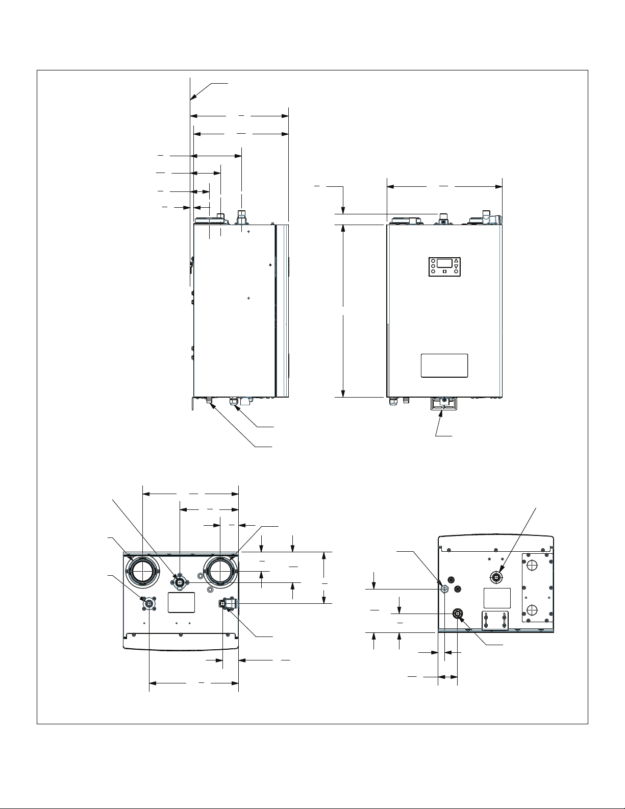
3.3 Dimensional Specifications
3
7
"
4
9
4
"
16
7
2
"
8
1
"
2
MOUNTING WALL SURFACE
7
14
"
8
5
14
"
16
1
5
"
8
17
7
"
16
26"
GAS INLET
3/4 NPT
EXHAUST PORT 3"
HOT WATER OUT
3/4 NPT
14
13
TOP VIEW
7
"
16
8
1
"
2
SIDE VIEW
7
"
8
3
2
"
4
POWER CORD
CONDENSATE DRAIN
FRESH AIR INTAKE 3"
7
"
2
8
9
4
16
COLD WATER IN
3/4 NPT
7
2
"
16
BOTTEM MOUNTING
BRACKET
FRONT VIEW
3/4” DRAIN
POWER CORD
"
3
"
7
4
9
6
"
16
7
"
2
8
1"
2
15
"
16
CONDENSATE DRAIN
BOTTEM VIEW
GX200, GX250, GX200P, GX250P Technical Data 8
Page 8
3.4 Connections
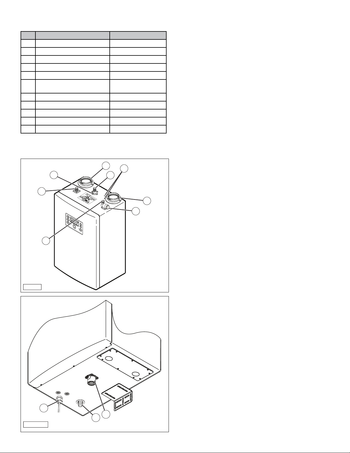
Item Description Specification1
1 Hot Water Outlet Connection 3/4” Male NPT
2 Exhaust Gas Vent 3” O.D.
3 Gas Supply Inlet Connection 3/4” Male NPT
4 Gas Pressure Analyzer Port 1/8” Female NPT
5 Fresh Air Intake 3” O.D.
6 Access Ports for Blower Mounting
Screws
7 Water Inlet Strainer —
8 Cold Water Supply Inlet Connection 3/4” Male NPT
9 Power Supply —
10 Condensate Drain Connection 3/4” Nipple (3/4” flex hose)
11 3/4” Drain Connection 3/4” Female NPT
1
Using sizes other than speci ed can cause damage to the water
heater and will void the warranty.
—
IQ-012
2
4
6
3
1
5
7
8
IQ-102
9
11
10
9 GX200, GX250, GX200P, GX250P
Technical Data
Page 9

4. Preparation Before Installation
4.1 Selecting an Installation Site
Note: When installing the water heater, follow all local
building codes and the current edition of the National
Fuel Gas Code (ANSI Z223.1/NFPA 54) in the USA, or
National Gas and Propane Installation Code (CAN/CGA
B149.1) in Canada when installing this product.
Note: For water heater installations in Massachusetts, the
unit must be installed by a plumber or gas-fitter
licensed within the Commonwealth of Massachusetts.
Refer to the Requirements for the State of
Massachusetts section in this manual for additional
information.
1. Select an interior location for the installation. Each
installation is unique; therefore, take the time to find the
best location for the water heater.
a. Install the water heater near locations that use hot
water, such as bathroom, kitchen, or laundry room
faucets.
b. Select a location that minimizes the length of the water
pipe.
c. If the distances are long or if the faucet or appliance
requires “instant” hot water, we recommend running
a recirculation line back to the water heater from the
farthest fixture.
d. Insulate the hot water supply and recirculation lines.
e. Select a location away from foot traffic and away from
areas where dust, debris, chemical agents, or other
combustible materials could accumulate.
f. Allow sufficient space for service and maintenance
access to all gas, water, and drain connections.
g. Make sure the location meets all building code
requirements.
h. Make sure the wall surface that the water heater is
mounted on will support the weight of the unit
(90 lbs. minimum).
2. Minimize the distance that the exhaust gas vent and fresh
air intake must travel to an exterior wall.
a. The exhaust vent outlet must not be located next
to a walkway, near soffit vents, crawl space vents,
or other areas where condensate (water vapor)
could cause damage or create a hazard. Refer to the
Venting Clearance Speci cations section for additional
information.
b. The fresh air inlet vent must be located at least 12”
from the exhaust vent.
c. Contaminated or dirty air drawn into the intake pipe
can damage the water heater. The warranty does not
cover damage caused by airborne contaminants.
3. Locate the unit close to a drain and near gas and water
connections.
The water heater produces a significant amount of
condensate during normal operation and should be
located near a suitable drain where damage from a
possible leak will be minimal. Installing the water heater
in a location without a drain will void the warranty
and the manufacturer will not be responsible for any
resulting water damages that may occur. For additional
information, refer to the Condensate Line Installation
section.
4. Locate the water heater and all the water pipes in an area
where the ambient temperature always remains above
freezing.
a. When the water heater is connected to an electrical
power supply, it will automatically prevent the water
from freezing inside the unit.
b. The unit’s freeze protection system will not prevent the
water in surrounding pipes from freezing.
NOTICE
In cold climates, if there is a power failure, the unit’s freeze
protection system will not operate and can result in water freezing
inside the heat exchanger. To prevent damage to the water
heater, turn OFF the gas supply and inlet water valve. Completely
drain the unit. Damage caused by freezing water is not covered
by the warranty.
5. Select an appropriate location for the combustion air and
exhaust pipes to exit the building, as shown in the Venting
Clearance Speci cations section in this manual.
Installation Preparation 10
Page 10
5. Wall Mounting
5.1 Clearance Requirements
In order for the water heater to operate properly and efficiently,
the clearances specified in the table are required.
Side
Back
Top
Side
Front
Bottom
IQ-043
IQ-013
STUDS
1
2
Required Mounting Clearances
Location From
Combustibles
Top 6” (15.2 cm) 2” (50.8 cm) 12” (30.4 cm)
2
Back
Sides 1” (25.4 mm) 1/2” (12.7 mm) 5/8” (15.8 mm)
Front 2” (5.1 cm) 2” (5.1 cm) 30” (76.2 cm)
Bottom 12” (30.4 cm) 12” (30.4 cm) 12” (30.4 cm)
1
Service clearances are suggested to allow for normal service.
2
Mounting bracket automatically sets this dimension.
5/8” (15.8 mm) 5/8” (15.8 mm) 5/8” (15.8 mm)
From Non-
Combustibles
Service
Clearance1
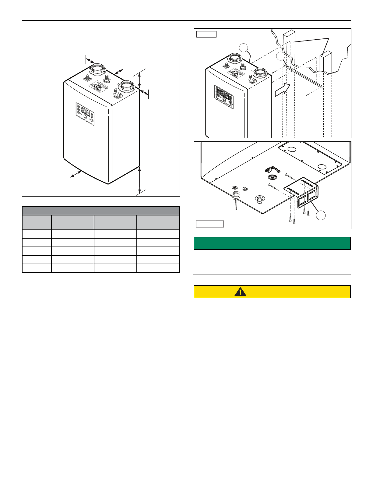
5.2 Mounting the Unit to the Wall
All water heaters come with an upper mounting bracket with
predrilled holes spaced on 16 inch centers to facilitate easy
installation on standard wall studs.
If the strength of the wall is insufficient or if the framing is
non-standard or uneven, reinforce the area using a sheet of
plywood before installing the water heater.
Avoid installation on inside walls that can transmit
operational noises to occupants while the unit is operating.
To mount the water heater to the wall:
1. Place the upper mounting bracket on the wall and ensure
that it is level. Use two appropriately sized wood screws
to mount the bracket securely to the studs. Ensure that it
is affixed securely and can support the weight of the 100
pound unit.
3
IQ-103
SAFETY
INSTRUCTIONS
Only the included brackets should be used to mount the
unit. Water heaters weigh approximately 100 lbs., and
must be securely attached to the wall.
CAUTION
According to the National Institute for Occupational Safety
and Health, the recommended maximum safe lifting
weight is 51 lbs., with all lifting conditions perfect; minimal
forward reach, steady load close to the body, straight
back, load between knees and shoulders, and good grips.
To avoid personal injury, always use these proper lifting
techniques and use two people to move the water heater
which weighs 100 lbs.
2. With assistance, hang the unit on the upper wall bracket,
interlocking bracket (1) on the back of the unit, and wall
bracket (2).
3. Install two appropriately sized wood screws in lower
bracket (3) to secure the unit to the wall.
4. Make sure the unit is plumb and level, and tighten the four
sheet metal screws on bottom bracket (3). When properly
installed, there should be a 5/8” air space between the
back of the water heater and the wall.
11 Wall Mounting
Page 11
6. Gas Connections
6.1 Installation Guidelines
WARNING
To avoid serious injury or even death, the gas line
installation and the gas line inlet pressure test
must be done by a licensed professional.
The water heater is factory preset for natural gas.
Make sure the gas line pressures are within normal
limits. Pressures outside normal limits can result in poor
performance and hazardous operating conditions.
1. Determine if the unit will use natural gas (factory preset)
or LP (propane) gas. To convert the unit to propane, refer
to the Propane (LPG) Conversion section in this manual.
2. Ensure the gas supply pressure meets the requirements
for the unit, as shown below.
GX250,
Gas Pressures GX200, GX200P
NG/LP- Minimum Static Gas Pressure 1/2”
black iron (non-corrugated)
NG/LP- Minimum Static Gas Pressure 3/4”
black iron (non-corrugated)
NG/LP - Maximum Static Gas Pressure 14”
Gas Pressure for Adjustments 8” for NG, 11” for LP
5” 6”
2.5”
3. Select the proper gas piping.
a. All gas piping and components must comply with
NFPA local codes and utility requirements. Only gas
approved fittings, valves, or pipes should be utilized.
b. Assembled piping should be clean of all scale, debris,
metal particles, or foreign material.
c. The piping must be supported by the floor, ceiling, or
walls.
4. Make sure the pipe diameter for the length being used
is correctly sized to meet maximum output of the water
heater(s) being installed.
a. The maximum gas flow rate required is the sum of the
maximum inputs of each unit divided by the heat of
combustion of the fuel supplied at the location (use
1,030 BTU per cubic foot for natural gas and 2,520 BTU
per cubic foot for propane).
b. The fuel supplier or utility company should be
consulted to confirm that sufficient volume and normal
pressure is provided to the building at the discharge
side of the gas meter or supply pipe.
c. Use the Gas Pipe Sizing tables in this manual or refer
to the gas line manufacturer’s sizing information to
determine the correct diameter for the supply pipe.
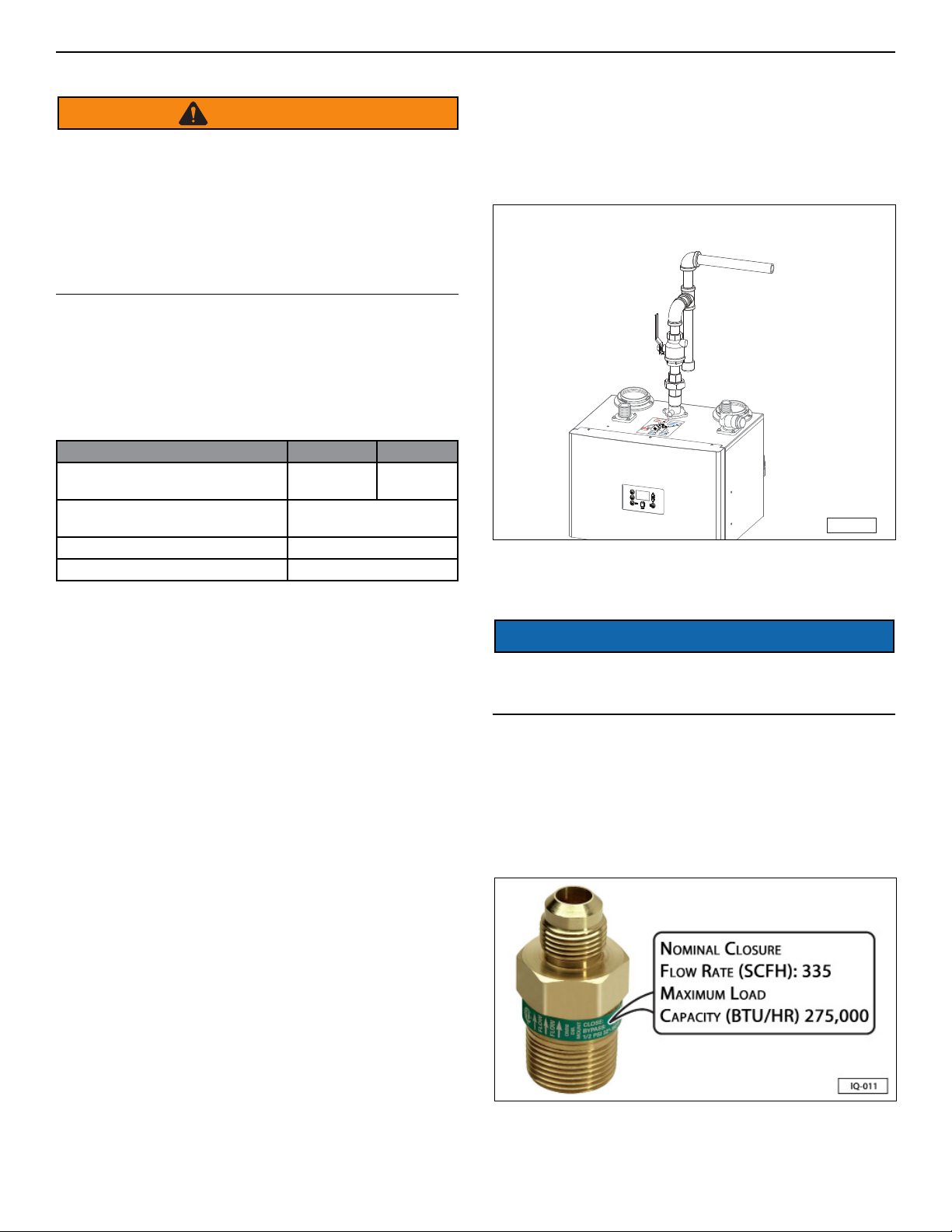
5. Make sure a drip leg is installed on the gas piping.
a. Drip legs are required at the gas supply of each water
heater to prevent any dirt, condensation, or debris
from entering the gas inlet.
GX250P
b. When multiple heaters are installed, some utilities and
local codes require a full size drip leg on the main gas
supply line in addition to the drip leg for each unit.
c. The bottom of the gas drip leg should be removable
without disassembling any gas piping.
d. The gas pipe should not be supported by the bottom
of the drip leg.
iQ-014
Note: Always clean the inside of the gas line of any dirt or
debris before connecting the piping to the unit.
NOTICE
Do not start the water heater until all connections have been
completed, leak-tested, and the heat exchanger is filled with
water.
6.2 Excess Flow Valve (EFV)
If an excess flow valve (EFV) is installed in the gas line, check
the manufacturer’s minimum and maximum flow capacity
rating. An improperly sized EFV will not allow for the full
flow of gas to the water heater and will cause the unit to
malfunction.
Gas Connection 12
Page 12
6.3 Gas Pipe Sizing Tables
This information is for reference only. Refer to gas pipe
manufacturer specifications for actual delivery capacity.
Contact the local gas supplier for actual BTU/ft3 rating. This
data copied from the National Fire Protection Association
Article 54 (NFPA 54).
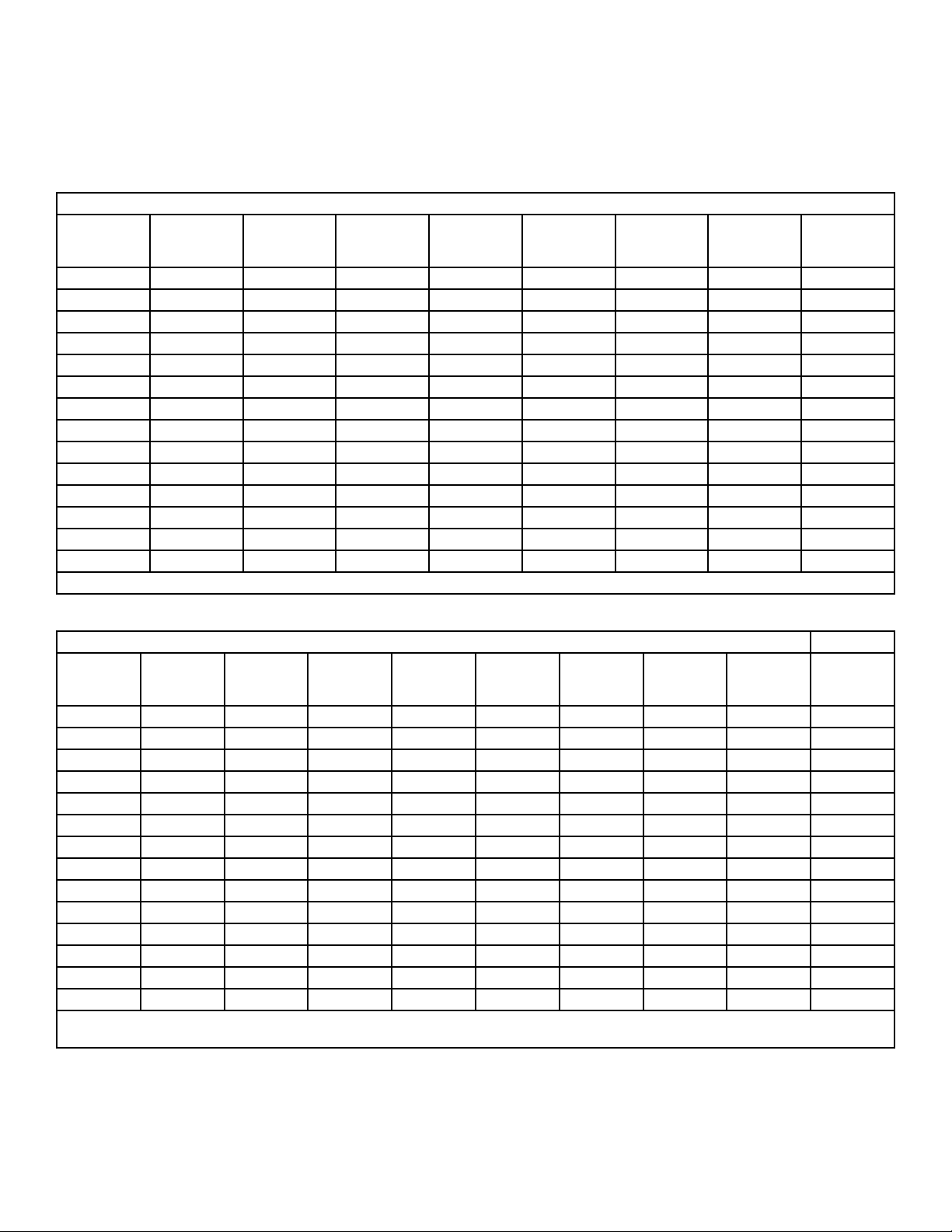
Pipe Sizes and BTU/h Capacity (Natural Gas). Use this table for static gas pressure less than 5”
Length
Including
fittings
10 360,000 678,000 1,390,000 2,090,000 4,020,000 6,400,000 11,300,000 23,100,000
20 247,000 466,000 957,000 1,430,000 2,760,000 4,400,000 7,780,000 15,900,000
30 199,000 374,000 768,000 1,150,000 2,220,000 3,530,000 6,250,000 12,700,000
40 - 320,000 657,000 985,000 1,900,000 3,020,000 5,350,000 10,900,000
50 - 284,000 583,000 873,000 1,680,000 2,680,000 4,740,000 9,660,000
60 - 257,000 528,000 791,000 1,520,000 2,430,000 4,290,000 8,760,000
70 - 237,000 486,000 728,000 1,400,000 2,230,000 3,950,000 8,050,000
80 - 220,000 452,000 677,000 1,300,000 2,080,000 3,670,000 7,490,000
90 - 207,000 424,000 635,000 1,220,000 1,950,000 3,450,000 7,030,000
100 - - 400,000 600,000 1,160,000 1,840,000 3,260,000 6,640,000
125 - - 355,000 532,000 1,020,000 1,630,000 2,890,000 5,890,000
150 - - 322,000 482,000 928,000 1,480,000 2,610,000 5,330,000
175 - - 296,000 443,000 854,000 1,360,000 2,410,000 4,910,000
200 - - 275,000 412,000 794,000 1,270,000 2,240,000 4,560,000
Note: BTU/h capacities are based on specific gravity of 0.6, pressure drop of 0.5” WC
3⁄4" 1" 1-1/4" 1-1/2" 2" 2-1/2" 3" 4"
Pipe Sizes and BTU/h Capacity (Natural Gas). Use this table for static gas pressure greater than 5”
Length
Including
fittings
10 404,000 949,000 1,787,000 3,669,000 5,497,000 10,588,000 16,875,000 29,832,000 43,678,000
20 286,000 652,000 1,228,000 2,522,000 3,778,000 7,277,000 11,598,000 20,503,000 30,020,000
30 233,000 524,000 986,000 2,025,000 3,034,000 5,844,000 9,314,000 16,465,000 24,107,000
40 202,000 448,000 844,000 1,733,000 2,597,000 5,001,000 7,971,000 14,092,000 20,632,000
50 - 397,000 748,000 1,536,000 2,302,000 4,433,000 7,065,000 12,489,000 18,286,000
60 - 360,000 678,000 1,392,000 2,085,000 4,016,000 6,401,000 11,316,000 16,569,000
70 - 331,000 624,000 1,280,000 1,919,000 3,695,000 5,889,000 10,411,000 15,243,000
80 - 308,000 580,000 1,191,000 1,785,000 3,437,000 5,479,000 9,685,000 14,181,000
90 - 289,000 544,000 1,118,000 1,675,000 3,225,000 5,140,000 9,087,000 13,305,000
100 - 273,000 514,000 1,056,000 1,582,000 3,046,000 4,856,000 8,584,000 12,568,000
125 - 242,000 456,000 936,000 1,402,000 2,700,000 4,303,000 7,608,000 11,139,000
150 - 219,000 413,000 848,000 1,270,000 2,446,000 3,899,000 6,893,000 10,093,000
175 - 202,000 380,000 780,000 1,169,000 2,251,000 3,587,000 6,342,000 9,285,000
200 - - 353,000 726,000 1,087,000 2,094,000 3,337,000 5,900,000 8,638,000
Note: For 1/2” line BTU/h capacities are based on specific gravity of 0.6, pressure drop of 4.6” WC and 5.0” WC. For all other line sizes, capacities are based on
specific gravity of 0.6, pressure drop of 3.0” WC
1/2" 3⁄4" 1" 1-1/4" 1-1/2" 2" 2-1/2" 3" 4"
13 Gas Connection
Page 13
Pipe sizes and BTU/h capacity (Propane). Use this table for static gas pressure greater than 5”
Length
Including
fittings
10 409,000 608,000 1,150,000 2,350,000 3,520,000 6,790,000 10,800,000 19,100,000 39,000,000
20 289,000 418,000 787,000 1,620,000 2,420,000 4,660,000 7,430,000 13,100,000 26,800,000
30 236,000 336,000 632,000 1,300,000 1,940,000 3,750,000 5,970,000 10,600,000 21,500,000
40 204,000 287,000 541,000 1,110,000 1,660,000 3,210,000 5,110,000 9,030,000 18,400,000
50 - 255,000 480,000 985,000 1,480,000 2,840,000 4,530,000 8,000,000 16,300,000
60 - 231,000 434,000 892,000 1,340,000 2,570,000 4,100,000 7,250,000 14,800,000
80 - 212,000 400,000 821,000 1,230,000 2,370,000 3,770,000 6,670,000 13,600,000
100 - - 372,000 763,000 1,140,000 2,200,000 3,510,000 6,210,000 12,700,000
125 - - 349,000 716,000 1,070,000 2,070,000 3,290,000 5,820,000 11,900,000
150 - - 330,000 677,000 1,010,000 1,950,000 3,110,000 5,500,000 11,200,000
175 - - 292,000 600,000 899,000 1,730,000 2,760,000 4,880,000 9,950,000
200 - - 265,000 543,000 814,000 1,570,000 2,500,000 4,420,000 9,010,000
Note: The line BTU/h capacities are based on specific gravity of 1.5, pressure drop of 0.5” WC.
1/2" 3⁄4" 1" 1-1/4" 1-1/2" 2" 2-1/2" 3" 4"
6.4 Gas Pressure Regulator
Depending on the gas inlet pressure at your location, it
may be necessary to install a gas pressure regulator to
lower gas pressures to an acceptable level. Please ensure
that the gas pressure regulator has the same or higher
minimum to maximum modulation range as the water heater
model it is connected to. In the case of multiple units, it is
recommended to use a dedicated gas pressure regulator for
each unit.
Regulators should be mounted with a minimum of 12” of
straight length pipe on either side.
6.5 Venting of Gas Supply Regulators
Below are the general guidelines for venting a gas regulator.
The manufacturer recommends these guidelines be followed
to ensure reliable and proper operation of the water heater.
Local codes and the gas regulator manufacturer should also
be consulted for additional installation information.
1. When venting the gas supply regulator, the vent pipe
must be at least the same size as the regulator vent.
2. When multiple units are connected, each regulator must
have a separate vent line.
3. Vent lines must not be connected together or connected
with any other appliance requiring external venting.
4. When selecting the size, the pipe diameter must be
increased by one size for every 20 feet of pipe.
5. Each 90° elbow is equivalent to approximately:
4.5 feet for nominal pipe sizes of up to 1-1/2”
10.5 feet for nominal pipe sizes of up to 4”
6. Each 45° elbow is equivalent to approximately:
2 feet for nominal pipe sizes of up to 1-1/2”
5 feet for nominal pipe sizes of up to 4”
Gas Connection 14
Page 14
7. Venting and Materials
WARNING
Improper venting of the water heater can result in excessive
levels of carbon monoxide, which can lead to severe
personal injury or death. This water heater must be vented
in accordance with the “Venting of Equipment “section of
the latest edition of the ANSI Z223.1 / NFPA 54 (Natural
Fuel Gas Code) in the USA, or in Canada refer to the
“Venting Systems and Air Supply for Appliances” section
in the latest version of CAN/CGA B149.1 (Natural Gas and
Propane Installation Code), and all applicable local
building codes. Vent installation should be performed
only by a licensed professional.
7.1 Venting Guidelines
• This water heater must be properly vented to ensure
there is a constant supply of clean intake air, and the
exhaust is properly evacuated from the building. All seal
connections should be airtight.
• The unit should be located as close to the vent
termination, and the vents kept as short and straight as
possible.
• Do not connect the water heater vent to a vent of any
other non-water heater appliance.
• Combustion air may be drawn from the room where the
unit is installed (single pipe/power vent) or directly from
the outside (two pipe/direct vent).
• Ensure a sufficient supply of clean combustion air, free
of any contaminants, such as dust, chemical fumes
(i.e. aerosols, chlorine, paint), grass, or other airborne
contaminants. If necessary, purchase and install the
appropriate air screens, and follow a regular cleaning
program to ensure an adequate supply of clean
combustion air.
• Do not operate the unit in an area that is or will be under
construction or renovation.
• The warranty does not cover damage caused by
contaminants in the installation area. If you must install
the water heater in an area with contaminated air, use
direct venting to supply the air from the outside of the
building.
• All horizontal runs should be sloped upwards towards
the vent termination at a rate of 1/4” per foot.
• To avoid moisture and frost build-up to openings on
adjacent homes, use 45° elbows, 90° elbows, or tees for
the vent termination to direct the exhaust fumes away
from the building.
7.2 Exhaust Vent Materials
The materials listed in the table below outline the acceptable
exhaust vent materials:
United States Exhaust Vent Pipe Standards
Material Description*
PVC Schedule 40
Exhaust
Vent Pipe
Canadian Exhaust Vent Pipe Standards
Material Description (approved to ULC-S636)**
Type BH Special Gas Vent Class IIA (PVC)
Exhaust
Vent Pipe
*Note: Do not use cellular foam core pipe for the exhaust.
**Note: The components (pipe, fittings, primers, and glues) must be from a
single manufacturer; do not interchange. Follow the vent manufacturer’s
certified instructions.
Type BH Special Gas Vent Class IIB (CPVC)
Type BH Special Gas Vent Class IIC (Polypropylene)
CPVC Schedule 40, 80
Approved Polypropylene
AL294C Stainless Steel
Type BH Special Gas Vent Class I
(AL294C Stainless Steel)
This water heater has a built-in exhaust vent temperature
control that limits the exhaust temperature to a maximum of
149°F (65°C).
If the temperature approaches the upper limit, the burner
will turn off automatically to protect the vent pipe. As a
result, this water heater can be vented with PVC pipe. Once
the exhaust temperature has dropped to a normal operating
level, the unit will automatically restart.
If the inlet/return water temperature will exceed 150°F
(66°C), do not use PVC venting. Refer to the Programming
section for Flue Type Selection (PVC or CPVC) for additional
information.
7.3 Air Intake Vent Materials
The air intake vent can be of any plastic or metal vent
material available. ABS, PVC, Polypropylene, galvanized steel,
and flexible corrugated ducting are all examples. If you are
using a corrugated material, ensure there is no inadvertent
crimping or blockage to the air intake pipe.
15 GX200, GX250, GX200P, GX250P Venting and
Materials
Page 15
7.4 Venting Configurations
Water heaters may be installed with:
two pipes (direct vent) configuration or with
one pipe (power vent) configuration.
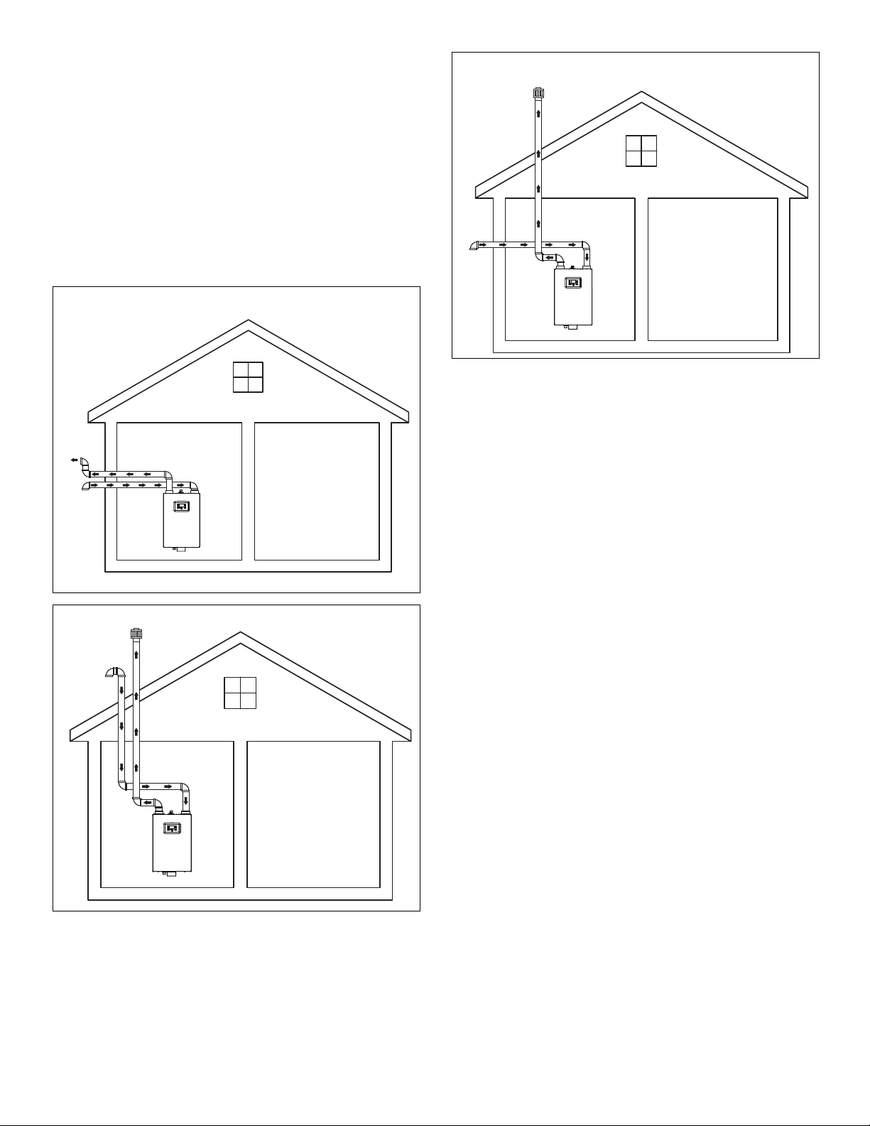
7.5 Two Pipe Vent System (Direct Vent)
The water heater can be direct vented without any
modification using a 3 inch diameter pipe.
The following diagrams represent some typical direct venting
configurations and are included to assist in designing the
vent system. Possible configurations are not limited to the
following diagrams.
Exhaust
Intake
Air
Exhaust
Intake
Air
Intake
Exhaust
Air
GX200, GX250, GX200P, GX250P Venting and Materials 16
Page 16
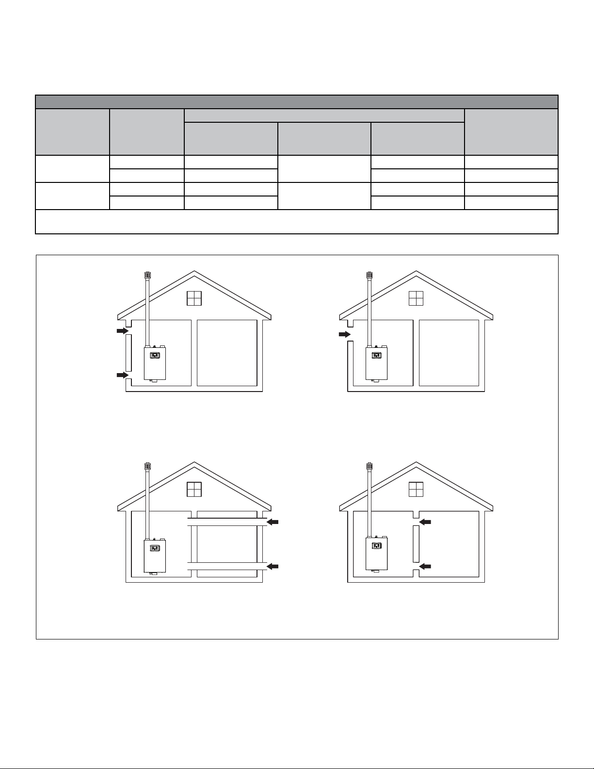
7.5.1 Single Pipe Venting System (Power Vent)
When using the single exhaust pipe/power vent method, the
following table outlines the required opening sizes for the
combustion and ventilation air coming into the room:
Required Combustion & Ventilation Air Opening Sizes (sq. in) Per Heater Per Room:
Air is drawn directly from outside into the room
Input
BTU/hr
199,950
250,000
*Where two openings are used, one must be within 12” of the oor and the other opening must be within 12” of the ceiling.
**Where one opening is required, it must be located within 12” of the ceiling. See illustration below.
Air Type
Combustion Air 50
Ventilation Air 50 100 67
Combustion Air 63
Ventilation Air 63 125 84
Exhaust Exhaust
Example #1
through two openings*,
direct or vertical
Example #2
through one opening**
67
84
Example #3
through two horizontal
ducts***
100 67
125 84
#1 #2
Example #4
Air is drawn from
another interior space
inside the building
Intake Air
Intake Air
Combustion Air Direct from Outside
2 Direct Openings or through Vertical Duct
1 sq. in. per 4000 btu/h
#3 #4
Intake Air
Intake Air
Combustion Air Through Ducts
2 Openings through Horizontal Duct
1 sq. in. per 2000 btu/h
Intake Air
Combustion Air Direct from Outside
1 Direct Opening
1 sq. in. per 3000 btu/h
Exhaust Exhaust
Intake Air
Intake Air
Combustion Air from Interior Space
2 Direct Openings or through Vertical Duct
1 sq. in. per 1000 btu/h
17 GX200, GX250, GX200P, GX250P Venting and
Materials
Page 17
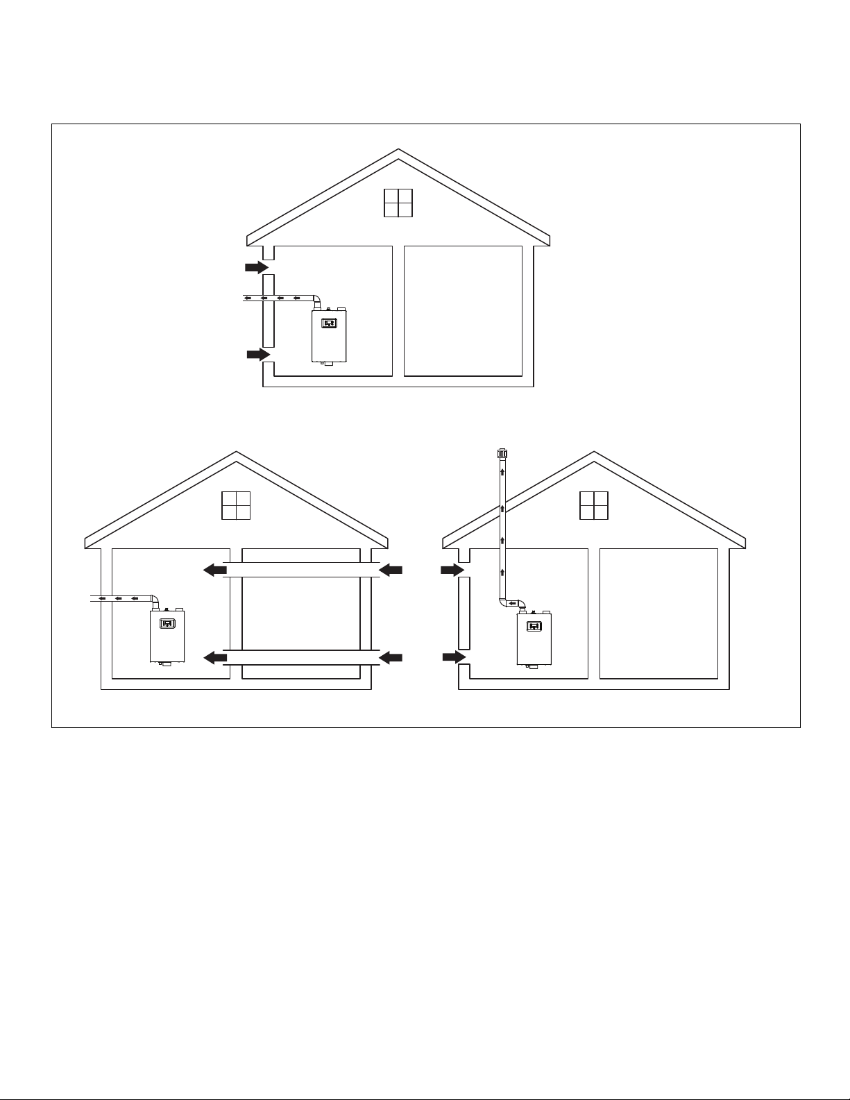
The following illustrations represent some typical power
venting configurations and are included to assist in designing
the vent system. Possible configurations are not limited to
these designs.
Intake Air
Exhaust
Intake Air
Exhaust
Exhaust
Intake
Air
Intake
Air
GX200, GX250, GX200P, GX250P Venting and Materials 18
Page 18
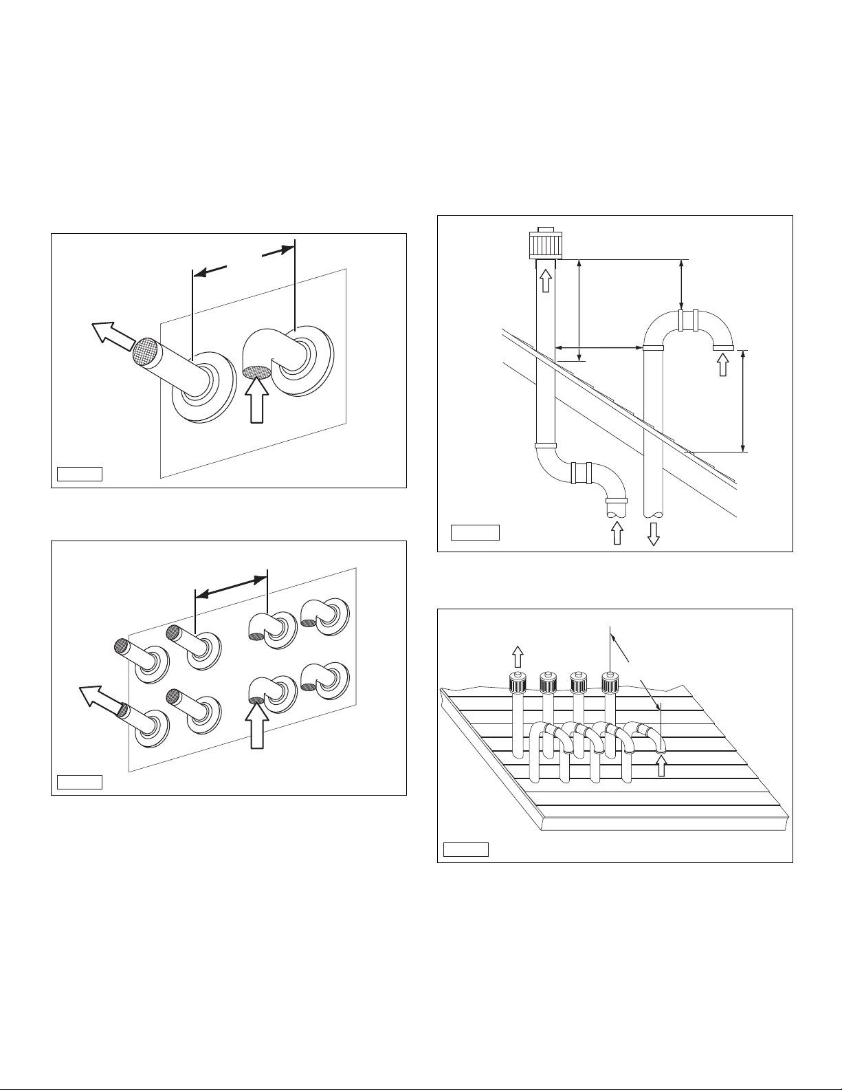
7.6 Venting Termination
7.6.1 Side Wall Termination
1. Terminate the air intake with a 90° elbow (angled down).
Use a flange and PVC screen (not supplied).
2. Terminate the exhaust on the exterior wall at least 12”
above ground and at least 12” away from the air intake, or
as required by local building codes. In areas of high snow
fall, protect the vent terminations from blockage. Use a
flange and PVC guard.
7.6.2 Roof Termination
Venting the unit through the roof is also an option. With this
installation method, the terminations must extend at least 12”
over maximum potential snow levels, or as required by local
building codes. In areas of high snow fall, protect the vent
terminations from blockage.
Terminate the air intake with a 90° elbow (angled down). A
suitable roof flashing and vent cap (not supplied) should be
installed.
Exhaust
IQ-020
Single unit.
12”
See
Note A
Intake Air
IQ-021
Single unit.
Exhaust
12” USA or
18” Canada
over maximum
snow level or
as required by
local code
3’ Minimum
Exhaust
12” Minimum
12” USA or
18” Canada
over maximum
snow level or as
required by local
code
Intake Air
Exhaust
Intake Air
IQ-020a
Multiple units.
Note A: The distance between any exhaust outlet and air
intake should be between 18 and 36 inches or
greater than 72 inches.
See
Note A
Intake Air
IQ-021a
Multiple units.
Note A: The distance between any exhaust outlet and air
intake should be between 18 and 36 inches or
greater than 72 inches.
19 GX200, GX250, GX200P, GX250P Venting and
Materials
Page 19
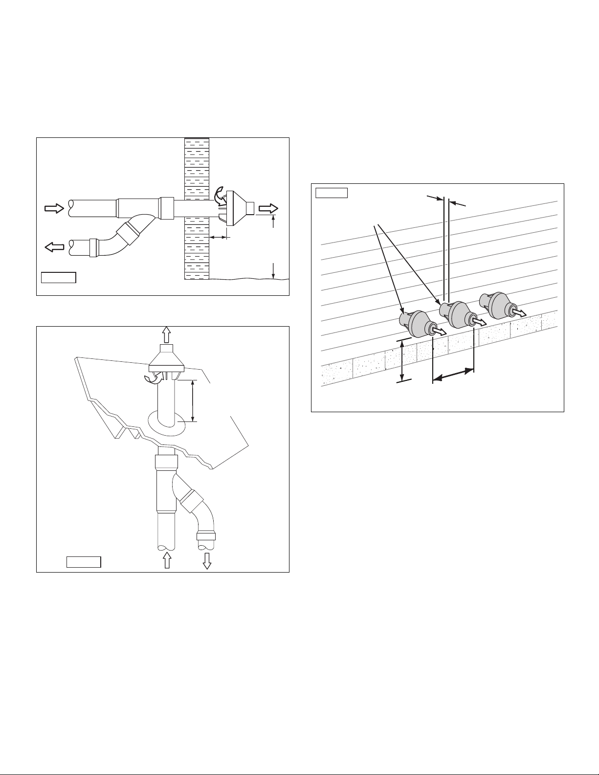
7.6.3 Concentric Venting Termination (Single Unit)
VENT
12” MINUMUM
TO MAXIMUM
EXPECTED
SNOW LEVEL
If desired, an optional concentric venting system, which uses
one 5” opening through an exterior wall or roof, can be used,
as opposed to cutting two 3” openings.
Follow all installation instructions included with the
concentric vent kit when installing this type of vent system.
Intake
Air
1”
Exhaust
12” above
anticipated
snow level
or grade.
Highest
Exhaust
Intake Air
IQ-022
Concentric Venting System Through a Side Wall.
Exhaust
7.6.4 Concentric Venting Termination (Multiple
Units
In order to conform to some national codes, when two or
more water heaters are installed they must be individually
vented. When two or more units are vented near each other,
each vent termination must be installed, as shown, to avoid
recirculation of flue gases. A minimum distance of 18 inches
must be maintained between each vent termination.
Follow all installation instructions included with the
concentric vent kit when installing this type of vent system.
IQ-083
COMBUSTION AIR
1” MAXIMUM (TYP)
VENT
VENT
Intake Air
IQ-023
Exhaust
Concentric Venting System Through the Roof.
12” USA or 18” Canada
Over maximum snow
level or as required by
local code
Intake Air
12” MINUMUM
12” MINUMUM
TO MAXIMUM
TO MAXIMUM
EXPECTED
EXPECTED
SNOW LEVEL
SNOW LEVEL
See
Note A
Multiple concentric units.
Note A: The distance between any exhaust outlet and air
intake should be between 18 and 36 inches or
greater than 72 inches.
GX200, GX250, GX200P, GX250P Venting and Materials 20
Page 20

7.7 Venting Clearance Specifications
H
D
G
V
A
Inside Corner
Detail
IQ-010
Item Description
A Clearances above grade, veranda, porch, deck, or balcony 1 foot 1 foot
B Clearances to window or door that may be opened 1 foot** 3 feet
C Clearances to permanently closed window * *
D Vertical clearance to a ventilated soffit, eves, or overhang * *
E Clearances to unventilated soffit, eves, or overhang * *
F Clearances to outside corner **
G Clearances to inside corner **
H Clearances to each side of centerline extended from meter/regulator * 3 feet within a height
I Clearances to gas meter regulator vent outlet * 3 feet
J Clearances to non-mechanical air supply inlet or combustion air inlet to any other appliance 1 foot** 3 feet
K Clearances to mechanical air supply inlet 3 feet above if within
L Clearances to above paved sidewalk or paved driveway on public property * 7 feet
M Clearances under veranda, porch, deck, or balcony * 1 foot
*Per local/gas supplier codes. Use clearances in accordance with local building codes and local gas supplier.
** For single vent pipe/direct 4 feet (1.2 m) below or to the side of opening and 1 foot above opening.
1
In accordance with Z223.1
2
In accordance with CSA B149.1
E
V
Air Inside Inlet
X
V
Vent Terminal
Area Where Terminal is Not Permitted
B
V
Operable
B
B
B
Fixed
Closed
V
I
X
V
J
A
Gas Meter/Regulator
Venting Clearance Specifications
Fixed
Closed
Operable
C
V
V
F
B
B
M
V
L
X
V
K
Clearance Distance
USA1 Canada2
15 feet above meter/
regulator assembly
6 feet
10 feet horizontally
21 GX200, GX250, GX200P, GX250P Venting and
Materials
Page 21

7.8 Common Venting for Multiple Units
Connecting several units together requires proper sizing of
the intake and exhaust pipes. Up to ten water heaters can be
connected (cascading) together.
Number of
Units common
vented
together
7.8.1 Vent Diameter Sizing and Lengths
The water heaters are designed for 3 inch air intake and gas
exhaust vents. The following chart outlines the maximum
length of venting allowable for each model. A vent system’s
length is calculated by adding the length of all straight
pieces used (both horizontal and vertical) and then adding
the equivalent lengths of each fitting used in the system. A
vent system’s length must not exceed the maximum length
outlined in the chart below:
GX200 and GX200P Maximum Vent Length (in
feet) for Power Vent (1 pipe)
Number of
Units common
vented
together
1 26 200 200
2 200
3 100 200
4 200
5 200
6 200
7 150
8 100 200
9 200
10 200
2” 3” 4” 6” 8”
Note: Reduce the maximum equivalent length above by 5 feet
per 90° elbow used and by 2 feet per 45° elbow used.
Do not exceed the above set limits.
GX200 and GX200P Maximum Vent Length (in
feet) for Direct Vent (2 pipe)
Number of
Units common
vented
together
1 21 100 100
2 100
3 50 100
4 100
5 100
6 100
775
8 50 100
9 100
10 100
2” 3” 4” 6” 8”
Note: Reduce the maximum equivalent length above by 5 feet
per 90° elbow used and by 2 feet per 45° elbow used.
Do not exceed the above set limits.
Duct Size
Duct Size
Note: Reduce the maximum equivalent length above by 5 feet
Number of
Units common
vented
together
Note: Reduce the maximum equivalent length above by 5 feet
GX250 and GX250P Maximum Vent Length (in
feet) for Power Vent (1 pipe)
Duct Size
3” 4” 6” 8”
1 130 130
2 130
3 30 130
4 130
5 130
6 130
745
8 30 130
9 130
10 130
per 90° elbow used and by 2 feet per 45° elbow used.
Do not exceed the above set limits.
GX250 and GX250P Maximum Vent Length (in
feet) for Direct Vent (2 pipe)
Duct Size
3” 4” 6” 8”
16565
265
33065
465
565
665
745
83065
965
10 65
per 90° elbow used and by 2 feet per 45° elbow used.
Do not exceed the above set limits.
GX200, GX250, GX200P, GX250P Venting and Materials 22
Page 22

7.8.2 Recommended Exhaust Pipe Transitions
Do not use a 90 degree t- tting for the gas exhaust.
Do not use 90 degree transition into a reducer or a straight pipe.
1/4” Rise Per
Foot Run
Condensate
Drain
45°
3X DIA. MIN
Do not direct gas exhaust from opposite directions. Use a 45 degree
transition, as shown.
1/4” Rise Per
Do not use reducers in a straight run of pipe.
Foot Run
Condensate
Drain
Do not transition into a reducer or use a t- tting. Transitions should
always be directed into a straight run of pipe.
23 GX200, GX250, GX200P, GX250P Venting and
Materials
Page 23

7.8.3 Two Pipe Vent System (Direct Vent)
The water heater can be direct vented without any
modification using a 3 inch diameter pipe when installing
single units. When more than one unit is installed, refer to
“7.8.1 Vent Diameter Sizing and Lengths” on page 22.
The following diagrams represent some typical direct venting
configurations and are included to assist in designing the
vent system. Possible configurations are not limited to the
following diagrams.
MAKE
UP AIR
MAKE
UP AIR
MAKE
UP AIR
GX200, GX250, GX200P, GX250P Venting and Materials 24
Page 24

7.8.4 Single Pipe Venting System (Power Vent)
When using the single exhaust pipe/power vent method, the
following table outlines the required opening sizes for the
combustion and ventilation air coming into the room: When
installing multiple units, refer to “7.8.1 Vent Diameter Sizing
and Lengths” on page 22.
MAKE
UP AIR
MAKE
UP AIR
MAKE
UP AIR
MAKE
UP AIR
MAKE
UP AIR
MAKE
UP AIR
DECOMMISSIONED
AIR INTAKE AND EXHAUST
25 GX200, GX250, GX200P, GX250P Venting and
Materials
Page 25

8. Water Connections
8.1 Water Line Connection Guidelines
Note: Ensure the water flow rate does not change faster than
1 GPM every 5 seconds. Flow rate changes faster than
this cause the unit to malfunction and result in a (E7
Error) code.
When making the water-side connections, please follow these
guidelines:
• Since each installation is different, it is up to the installer to
route the water lines in the most efficient manner.
• Keep the hot water pipes as short as possible to deliver hot
water to the fixtures quickly.
• Only materials (pipes, fittings, valves, solder, etc.) that are
approved for use in potable water systems should be used.
• When tightening any fittings to the connections on the
water heater, care should be exercised not to overtighten
these joints and damage the unit.
• Unions and manual shut-off valves on the cold water inlet
and hot water outlet are recommended.
• Isolation valve kits can be used if incoming water treatment
is anticipated (such as a water softener) due to hardness
levels or heavy usage of the unit.
• To conserve energy, insulate all hot water piping, except
the condensate drain or pressure relief valve.
• When the water heater is installed in a closed loop
recirculation system, and if the cold water supply line has
a back flow preventer, then an expansion tank should be
installed to allow for water expansion.
• After installation, test the water heater for proper flow and
inspect for leaks.
• Run the hot water for a few minutes and then clean the
inlet water strainer located on the cold water inlet fitting.
This strainer must be cleaned periodically to maintain
proper water flow.
If the incoming water is known to have a high mineral
content or “hardness” (>15 ppm), treatment is recommended
upstream from the water heater.
8.3 Hot Water Side Connection
8.3.1 Installation Instructions
iQ-107
1. Connect a 3/4” NPT coupler to the water heater’s hot
water connection.
2. Install a 3/4” union connection.
3. Following local building codes, install a 3/4” manual
shut-off valve with 3/4” NPT fittings.
8.3.2 Pressure Relief Valve Installation
WARNING
To prevent serious personal injury, do not install any
shut-off device between the water heater and the pressure
relief valve. This valve is designed to release abnormally
high pressure within the water heater in the event of a
system problem.
8.2 Water Quality
Proper maintenance of the water heater is required to ensure
that your water meets EPA quality standards. The following
table shows the maximum contaminant levels allowed, based
on the EPA National Secondary Drinking Water Regulations
(40 CFR Part 143.3). If you suspect that your water is
contaminated in any way, discontinue use of the water heater
and contact an authorized technician or licensed professional.
Contaminant Maximum Allowable Level
Total Hardness 200 mg/l (12 grains/gallon)
Aluminum 0.05 to 0.2 mg/l
Chloride 250 mg/l
Copper 1.0 mg/l
Iron 0.3 mg/l
Manganese 0.05 mg/l
pH 6.5-8.5 mg/l
Sulfate 205 mg/l
Total Dissolved Solids (TDS) 500 mg/l
Zinc 205 mg/l
GX200, GX250, GX200P, GX250P Water Connections 26
Install a customer-supplied 3/4” 150 psi maximum pressure
relief valve with the appropriate BTU/HR rating into the 3/4”
female NPT port on the bottom of the unit.
Note: The water heater is designed with an internal high
temperature shut-off switch and, therefore, only a
pressure relief valve is required for these units.
IQ-106
Page 26

8.4 Cold Water Side Connection
Install and connect the cold water line.
SHUT-OFF
VALVE
1. Attach and tighten the flex hose with the loop to the barb
fitting located on the bottom of the unit.
IQ-105
UNION
IQ-108
1. Connect a 3/4” NPT coupler to the water heater’s cold
water connection.
2. Install a 3/4” union connection.
3. Following local building codes, install a 3/4” manual
shut-off valve with 3/4” NPT fittings.
4. Connect the unit to the existing cold water lines.
If the existing plumbing is 1/2” pipe, adapters may be used
to transition from the 3/4” pipe.
5. Leak test the water piping before placing the unit in
operation.
8.5 Condensate Line Installation
2. Follow applicable local codes and if required, install in-line
neutralizer (3) to treat the acidic condensate. Follow all
the installation instructions included with the neutralizer.
Note: Ensure that the flex tube is not pinched or kinked. The
tube should freely drain. The tube termination should
not be immersed in water.
3. Route the drain line to nearby laundry tub (6), floor drain
(5), or condensate pump (4).
WARNING
The drain line is shipped from the factory with a loop held
together with plastic ties. Do not remove the ties and/or
straighten the loop. This loop forms an air block (trap)
which prevents carbon monoxide from exiting the water
heater through the drain line. Improper installation of the
drain line can result in carbon monoxide build, which can
lead to severe personal injury or death.
1
3
2
4
5
27 GX200, GX250, GX200P, GX250P Water
6
IQ-027
Connections
Page 27

8.6 External Recirculation Options
The following illustrations provide possible external
recirculation options.
RETURN LINE OPTION
Cold
Hot
Optional
Isolation
Kit
Optional
Isolation
Kit
Hot Water
Cold Water
Note: A pressure relief valve can be installed into the hot
water isolation valve kit, if this option is used. With
this option, a customer-suppled, 3/4” NPT plug must
then be installed in the drain port on the bottom of
the unit.
Relief
Valve
Ball
Valve
KEY
UnionPressure
Check
Valve
GX200, GX250, GX200P, GX250P Water Connections 28
Page 28

UNDER SINK VALVE OPTION #1
Hot
Optional
Isolation
Kit
Cold
Optional
Isolation
Hot Water Cold Water
Kit
Cold
Courtesy
Grundfos
Relief
Valve
KEY
Ball
Valve
UnionPressure
UNDER SINK VALVE OPTION #2
Hot
Optional
Isolation
Kit
Hot Water Cold Water
Cold
Optional
Isolation
Kit
Courtesy
Armstrong “Astro”
Relief
Valve
KEY
Ball
Valve
UnionPressure
29 GX200, GX250, GX200P, GX250P Water
Connections
Page 29

9. Electrical
WARNING
To avoid serious injury or even death, follow all applicable
local, state, and national regulations, mandates, and building
codes for guidelines to install the electrical power supply.
9.1 Electrical Code Requirements
Electrical code requirements are different in the USA and
Canada. Refer to and follow the local building codes, the
latest edition of the National Electrical Code (NFPA 70) in the
USA, or the CGA C22.1 Canadian Electrical Code - Part 1.
The circuit breaker should be at least 15 amps.
15 Amp
Circuit
Breaker
9.2 Electrical Connection and Polarity
NOTICE
POLARITY
The plug provided with the unit is polarity sensitive. Ensure
that the line and neutral are at the correct locations in the
wall socket. If the polarity is reversed, it will cause the unit to
malfunction and turn off every 15 seconds.
Make sure the electrical outlet being used is wired with at
least 12 gauge wire and grounded. Only one water heater
should be plugged into an outlet with the 12 gauge wire. It
should also be connected to at least a 15 Amp circuit breaker.
The electrical power required for the water heater is 120V AC
at 60 Hz.
Use 15 Amp Breakers For Single Units.
Note: For an electrical wiring schematic, refer to the
Wiring Diagram section in this manual for additional
information.
Line
Neutral
Ground
IQ-029
SAFETY
INSTRUCTIONS
If desired, the water heater can be wired into the electrical
system by removing the power cord and replacing it with
electrical cable. If this method is used, a separate ON/OFF
switch must be installed to remove power from the unit.
Electrical 30
Page 30

10. Propane (LPG) Conversion
PROPANE
NATURAL
GAS
SAFETY
INSTRUCTIONS
A qualified service technician MUST make the required
changes to convert the water heater from Natural Gas to
LP Gas.
10.1 General Information
Before beginning the conversion, make sure the LP gas inlet
pressure is between 8.0” and 13.0” W.C. Record the gas
pressure here.
STATIC LP GAS PRESSURE ____________W.C.
DATE ___________________
10.2 Procedure
1. Make sure all hot water faucets are OFF. If required, press
the control panel Power button to turn the water heater
OFF. Disconnect the power.
2. Shut OFF the gas supply inlet valve closest to the unit, if
connected.
3. Remove the front cover and locate the main circuit board.
4. Locate DIP Switch 1 and change it to the PROPANE
position.
5. Reconnect the power and wait for main screen to appear.
6. Press and hold the Mode button until the rS screen
appears on the display.
Press the Mode button multiple times until the Ft screen
appears on the display. The current Fuel Type setting will
appear. Either nAt or Prop will be displayed to indicate
the position of the DIP switch.
PROPANE
PROPANE
DIP Switch Settings (Réglages des commutateurs DIP)
SW1 Propane
ON
Natural Gas
ON
(Gaz naturel)
NATURAL
NATURAL
GAS
GAS
IN-30
7. Press and hold the Enter button to return to the main
display.
8. Refer to Adjusting the CO2 Level section in this manual for
instructions on connecting a calibrated CO2 analyzer to
the gas valve.
31 Propane Conversion
Page 31

11. Adjusting CO2 Level
11.1 General Information
This procedure is required only during installation in a high
altitude location or when changing the unit from natural gas
to propane, or when experiencing combustion problems.
This procedure should only be done by a qualified technician.
DANGER
A concentration of carbon monoxide as small as 0.04%
(400 parts per million) in the air can be fatal. When making
high fire and/or low fire adjustments, CO levels must be
monitored using a flue gas analyzer so that the level of no
more than 400 ppm of CO is exceeded at any time during
the operation.
Adjusting the “low fire screw “ or the “high fire screw”
in small increments can result in a significant increase
in CO concentration. To avoid serious injury or death,
DO NOT make any adjustments to the gas valve without
monitoring the exhaust gases with a fully functional and
calibrated flue gas analyzer.
CO2 and CO Standards
Description CO2 Range (%) Max. CO Level (ppm)
Natural Gas
High Fire 8.8% to 9.1% < 200 ppm
Low Fire 8.6% to 8.9% < 60 ppm
LP Gas
High Fire 9.0% to 9.8% < 200 ppm
Low Fire 8.6% to 8.9% < 60 ppm
11.2 Procedure
1. Locate the gas valve.
2. Use a CO2 analyzer to measure the exhaust vent gas at the
bottom of the condensate trap.
3. Press and hold the Mode button for five seconds to access
the rS screen on the display.
4. Press and release the Mode button multiple times until the
CO screen appears on the display.
Hi will be displayed indicating the unit will fire at its
highest firing rate when a hot water faucet is opened.
5. Open several hot water faucets to allow at least 5 gpm of
water flow.
6. When the unit is operating at high firing – the shower,
blower, and flame icons will be displayed.
NOTICE
The values listed in the table are for nominal conditions.
Variables such as gas pressure, heating value of the gas, and
the humidity and temperature of combustion air can all impact
CO and CO2 values. Changes in these variables can result in
different CO and CO2 values on the same water heater.
A qualified service technician must use a calibrated CO2 analyzer
to adjust the gas valve to achieve the desired CO2 and CO values.
It is recommended that before any adjustments are
made, the gas pressure to the unit be as follows:
NG - 8” W.C.
LP - 11” W.C.
The service technician must confirm Static gas pressures before
setting High Fire and Low Fire CO2 and CO values.
7. Record values in table column 1, ‘Hi’. If the CO2 values are
within the 8.8%-9.1% range, proceed to step 9, otherwise
continue with Step 8.
Adjusting CO2 Level 32
Page 32

8. Use a flat blade screwdriver to adjust the gas valve high
fire screw to achieve the desired CO
values.
2
Note: Turn clockwise to decrease CO2 and counterclockwise
to increase CO
increments. Wait three minutes for reading to stabilize
. Make adjustments by making 1/4 turn
.
2
and then record the combustion analyzer values for
CO2 and CO.
IN-32
High Fire Screw
9. Once the desired values are achieved, record the new
HIGH FIRE CO
CO2 Value %
Max CO ppm
Date
values in table column 2, ‘Adjusted Hi’.
2
CO2 and CO Recorded Values
Hi Adjusted Hi Lo Adjusted Lo
12. Adjust the Low Fire screw while the burner operates at
low fire using a 2 mm hex wrench. Turn clockwise to
increase CO
and counterclockwise to decrease CO
2
Low Fire Screw
.
.
2
IN-33
13. Once the desired values are achieved, record the LOW
FIRE CO
values in table column 4, ‘Adjusted Lo’.
2
14. Remove the combustion analyzer.
15. Turn off water flow
16. Press and hold the Enter button to return to home screen
to resume operation.
10. Press the Down arrow key to let the unit fire at low fire.
11. Record values in table column 3, ‘Lo’. If the CO2 values
are within the 8.6%-8.9% range, proceed to Step 14,
otherwise continue with Step 12.
33 Adjusting CO2 Level
Page 33

12. Operation
12.1 Control Panel
G
F
Mode
Time
E
D
A) LCD screen
The LCD display screen shows all information about the
operating functions of the water heater.
A
B) Arrow keys
Press the UP or DOWN arrows to adjust the value of the
selected feature, such as time or water temperature.
C) Enter button
To return to the Main or Home screen.
B
D) Power button
When the water heater is initially connected to an electrical
Enter
Power
power supply, the unit will automatically turn ON and the
display panel should light up. To turn the unit OFF, press
and hold the Power button and the water heater will go
through a shutdown process. The unit can then be turned
ON again, once the blower finishes its purge cycle (10
C
seconds) by pressing the Power button.
E) Time button
Press this button to set the hours and minutes on the clock.
F) Mode button
Press this button to access various Modes of Operation.
G) Orange button
Used to view real time flow and temperature readings.
12.2 Display Icons
KMNOPQR
J
I
H
T
H) Displays the current time in AM or PM.
I) Displays the CODE icon and the most recent digital error
code.
J) Displays the INLET icon and the actual inlet water
temperature in degrees Fahrenheit or Celsius.
K) Indicates an error has been detected and a trouble code
may be shown next to the CODE icon.
S
L) Not Used
M) Warns of freezing conditions within the water heater. The
water heater is designed to turn ON to prevent freezing of
the internal water pipes.
N) Indicates internal pump is ON.
O) Indicates water flow (open faucet).
P) Indicates blower is ON.
Q) Indicates burner is ON.
R) Indicates the level of energy usage. There are four “bar”
indicators and each represent 25% of gas usage.
S) Indicates outlet water temperature.
T) Indicates multiple units are daisy chained and programed.
GX200, GX250, GX200P, GX250P Operation 34
Page 34

12.3 Turning Water Heater ON and OFF
1. To turn the water heater ON press the Power button. The
home screen will automatically display when the unit is
ready to use.
2. To turn the water heater OFF, press and hold the
Power button for three seconds. The home screen will
automatically display when the unit is ready to use.
12.4 Resetting (Clear) Error Codes
1. To reset the water heater and clear all error codes, press
and release Power button.
4. Press the Up/Down arrows to set the correct hour. When
setting the hour, make sure you have correctly advanced
the time to either the AM
or PM hour setting.
5. Press and release the Time button again.
12.5 Setting the Time
1. Press and release the Time button.
The minute section of the time display will flash.
2. Press the Up/Down arrows to set the correct minute.
The colon (:) between the hours and minutes should now
be flashing, indicating the time has been properly set.
3. Press and release the Time button again.
The hour section of the time display will flash.
35 GX200, GX250, GX200P, GX250P
Operation
Page 35

12.6 Adjusting the Water Temperature
12.6.1 General Information
These commercial water heaters are capable of heating water
to 185°F.
Note: The outlet water temperature is factory preset to
120°F.
WARNING
Hot water temperature over 125°F (52°C)
can cause severe burns instantly or death
from scalding. Children, the disabled, and
the elderly are at the highest risk of being
scalded. Do not leave children or the infirm
unsupervised. Check temperature of hot
water before taking a shower or bath. To
control water temperature to a particular faucet,
temperature limiting valves can be installed by your
service professional.
All water faucets must be closed before changing the
temperature setting. The unit must not be operating
(burner icon not on).
12.7 Real Time Temperature and Flow of the System
Press and hold the Orange button.
The flow screen Flo indicates gallons per minute (gpm). This
screen alternates between Flo and the actual gallons per
minute. The first two digits are gallons and the second two
digits are a portion of one gallon. For example 3:05 is 3.05
gallons per minute.
12.6.2 Adjustment Procedure
Press the Up/Down arrows to set the desired temperature
range from 100 to 140°F in one degree increments.
For setting the temperature above 140°F, press and
continue to hold the Orange button while pressing the Up
arrow. Continue pressing the Up button until the desired
temperature range is reached.
Note: The actual water temperature will also be displayed
(116°F).
Release the Orange button to return to the home screen.
12.8 Flue and Domestic Water Temperature
When the Orange button is held down, the left-hand side
of the display scrolls through the following parameters in
succession:
Flow Rate
Flo followed by 3:05 (Indicated flow rate of 3.05 GPM).
Flue Temperature
FLUE and the actual temperature of flue, such as 110°F.
Once the desired temperature is selected, the unit will heat
water up to that temperature.
When the Orange button is released, the Home screen will
appear.
GX200, GX250, GX200P, GX250P Operation 36
Page 36

Domestic Outlet Water Temperature
tout and the actual domestic hot water (DHW) outlet
temperature, such as 120°F
12.9 Error Screen
If an error occurs, the display will indicate the error code (E3).
The safety alert symbol will also be flashing.
If the safety alert symbol is visible but not flashing, it means
that communication between the units was interrupted, but
has since been reestablished.
37 GX200, GX250, GX200P, GX250P
Operation
Page 37

13. Programming
13.1 Modes of Operation
The Modes of Operation screens provide set up screens and
additional information on the water heater. There are five
Mode of Operation screens which are used by the technician
during installation or maintenance of the water heater.
13.1.1 Standard Modes
1. Press and release the Mode button until the desired screen
shows on the display.
dC - Daisy Chain
FC - Flow Control
PH - Performance History
IH - Setting Instant Hot Water Times*
dE - Diagnostic Error
* Applies only to GX200P and GX250P models.
2. Follow the instructions in the specific section to enter the
desired settings.
2. Remove the front covers and locate the main circuit
boards on the first and last units.
3. Locate DIP Switch 3 on the first and last units and position
the switch in the ON position. On all the middle units,
position the switch in the OFF position.
ON
OFF
IN-61a
13.1.2 Advanced Modes
1. Press and hold the Mode button for five seconds until
the rS screen appears. Now press and release the Mode
button multiple times until the desired screen shows on
the display.
rS - Burner Rate Ramp Setting
Ft - Fuel Type
CE - Common Exhaust
FP - Flue Pipe Type
CO - Adjust CO2 Level
2. Follow the instructions in the specific section to enter the
desired settings.
13.2 Viewing and Setting Modes of Operation
13.2.1 Daisy Chain
4. Using the supplied cables, connect one end of a cable
into either of two jack receptacles (arrows) located on the
circuit board and the other end to the jack in the next
unit.
Set DIP Switches
1. Disconnect the power from all the units in the system.
WARNING
SHOCK HAZARD
Before making any adjustments or connections inside the
water heater cabinet, make sure the power is disconnected.
Unplug the water and/or turn the circuit breaker OFF.
GX200, GX250, GX200P, GX250P Programming 38
IN-61
Page 38

5. Pass the cable through the grommet located at the
bottom of the cabinet.
6. Secure the cable using a zip tie.
123
13.2.2 Flow Control Selection
Press the Mode button multiple times until the
FC screen appears on the display.
The current setting will be shown on the display.
Dip Switch 3
ON
Dip Switch 3
OFF
Dip Switch 3
ON
IH-61a
7. Replace the front covers.
Set Up Unit Number
1. Reconnect the power and wait for the home screen to
appear.
2. Press and release the Mode button until the dC screen
appears. The designated number for the unit will be
displayed. The default is OFF.
3. Now, press the Up/Down arrows to select the desired
number for the particular water heater. Change the
selection from OFF to one of the ten possible selections
(01, 02, 03, though 10). The up/down arrows scroll from
OFF to 1 through 10 and then to OFF.
4. Once the desired number is selected, press and hold the
Enter button for three seconds to save this setting and
return to the main display screen.
5. Repeat the above steps and set each unit to a different
number. For example, the next unit would be 02, the
third unit would be 03, and so on.
The water control valve is set to ON for temperature priority
and OFF for maximum flow.
Press the Up/Down arrows to select either ON or OFF.
Press and hold the Enter button for three seconds to save the
settings and return to the home screen.
Note: If the Enter button is not pressed within 30 seconds of
inactivity, the display will return to the home screen.
39 GX200, GX250, GX200P, GX250P
Programming
Page 39

13.2.3 Performance History
13.2.4 Setting Instant Hot Water Times
The Performance History mode allows the
technician to view ignition cycles, number of ON
times, and cumulative water flow. The displayed
results are for all the water heater modules
combined within the unit.
Press the Mode button multiple times until the PH screen
appears.
The Flow-On Hours FH, Firing Counts FC, and Cumulative
Flow CF, will now begin to display for 1.5 seconds each. The
display will continue to cycle for 30 seconds and then return
to the home screen. Some examples are shown below.
Diagnostic Code FH (Flow-on hours)
shows one hour of flame. (To obtain
the total hours, multiply the number
by 10).
Diagnostic Code FC (Firing Count)
shows a flame count of 40,000. (To
obt ain the total number, multiply
the number by 1,000).
This mode is used to set the times when the unit
will supply instant hot water.
This mode can only be accessed when Flame icon is
NOT showing on the display.
Push Mode button multiple times until IH appears on the
display.
The current setting will show in the time area of the display as
Auto, 24-7, Pat1, Pat2, Pat3, Pat4, or nonE.
The default setting is AUtO and the learned times will be
displayed.
Diagnostic Code CF (Cumulative
Flow) shows 38,000 gallons of
water. (To obtain the usage in
gallons, multiply the number by
1,000).
Press and hold the Enter button for three seconds to return to
the home screen.
Note: If the Enter button is not pressed within 30 seconds of
inactivity, the display will return to the home screen.
Press the Up/Down arrows to toggle between the available
six patterns (Auto, 24-7, Pat1, Pat2, Pat3, Pat4, or nonE).
Once the desired pattern is selected, press and hold the Enter
button for three seconds to save the settings and return to
the home screen.
If the Enter button is not pressed within the 30 second time
limit, the setting will not be saved.
GX200, GX250, GX200P, GX250P Programming 40
Page 40

13.2.5 Diagnostic Code and Error Log Selection
13.2.6 Blower Ramp Selection
This screen provides the technician with Diagnostic
Codes and Errors recorded as the water heater
operates. These codes are used in conjunction with
the Performance History Codes.
Error Code Description of Error Code
E1
E3
E7
E9
EA
EC
Ed
Flashing
Warning Icon
Flashing
Cascading Icon
Flashing
Recirculation
Icon
* If Eb is displayed, please call the factory for service instructions.
Blower Speed Fault
Blocked Flue Fault
Ignition Failure
Temperature Sensor Shorted
Temperature Sensor Open Circuit
Flue Temperature Exceeded Set Limit
Heat Exchanger Outlet Temperature Exceeded
Set Limit
Error Code and Unit Locked Out
Loss of Communication Between Units
Pump Is Not Operating
When exhaust harmonics are observed, i.e.
resonance at low fire, adjust the water heater using
the blower ramp setting (default is rat3). Increase
the rate number until the resonance is no longer
observed.
The Blower Ramp Selection has five different settings
(rat1 - rat5):
Press and hold the Mode button for five seconds to access
the rS screen on the display. The current setting will be
displayed.
Press the Up/Down arrows to select the Blower Ramp
Selection from five different settings (rat1 - rat5).
Select a ramp rate at which the harmonics disappears during
operation.
Press and release the Mode button multiple times until the
dE screen appears.
The 01:E1 screen is the most recent code, while the 10:E3
is the last viewable screen. Refer the examples below for
further clarification.
Example of latest diagnostic code
Fan Speed Error Code E1.
Example of the last viewable code
Blocked Flue Fault Code E3.
Press and hold the Enter button for three seconds to return to
the home screen.
Note: If the Enter button is not pressed within 30 seconds of
inactivity, the display will return to the home screen.
Press and hold the Enter button for three seconds to save the
settings and return to the home screen.
Note: If the Enter button is not pressed within 30 seconds of
inactivity, the display will return to the home screen.
41 GX200, GX250, GX200P, GX250P
Programming
Page 41

13.2.7 Fuel Type Verification
13.2.8 Common Exhaust Venting
The Fuel Type mode screen shows the selected fuel
type; natural gas (factory preset) or Propane.
Operation with natural gas is factory preset. Refer
to the Propane (LPG) Conversion section in this
manual for additional set up information.
Press and hold the Mode button for five seconds to access the
rS screen on the display.
Press and release the Mode button until the Ft screen appears
on the display. The current Fuel Type setting will appear (nAt
or PrOP) to indicate the position of DIP switch 3 on the circuit
boards. Fuel type cannot be changed from the screen.
Changing this setting can only be done when the
Flame ON icon is not displayed.
This mode is applicable when multiple units are connected
together. Turning the CE mode ON allows multiple units
to be vented into a common vent. Refer to the Venting for
Commercial Application section for information on common
venting guidelines.
Press and hold the Mode button until the rS screen appears.
Press and release the Mode button multiple times until the
CE screen appears. The current setting will be displayed.
The default setting for this mode in ON.
Press the Up/Down arrows to select either ON or OFF.
To change fuel type from factory set natural gas to propane,
follow the Propane Conversion procedure in this manual.
Press and hold the Enter button for three seconds to return to
the home screen.
Note: If the Enter button is not pressed within 30 seconds of
inactivity, the display will return to the home screen.
Press the Enter button to save the changes and return to the
main display.
Note: If the Enter button is not pressed within 30 seconds of
inactivity, the display will return to the home screen.
GX200, GX250, GX200P, GX250P Programming 42
Page 42

13.2.9 Flue Pipe Selection (PVC or CPVC)
13.2.10 Adjusting CO2 Levels Selection
Changing this setting can only be done when the
Flame ON icon is not displayed.
WARNING
When the unit is set for CPVC or polypropylene pipe,
flue temperatures can reach 185°F. PVC pipe will
lose integrity at temperatures above 149°F. Make
sure FP setting and the type of material being used for the
flue are compatible.
Press and hold the Mode button until the rS screen appears.
Press the Mode button multiple times until the FP screen
appears. The current setting will be displayed.
The default setting for this mode is PVC.
Refer to the Adjusting the CO2 Level section in this
manual.
Press the Up/Down arrows to select the desired setting of
either PUC or CPUC.
Note: The flue temperature for PVC material must not
exceed 149°F. The flue temperature for CPVC or
Polypropylene material must not exceed 185°F.
Press the Enter button to save the changes and return to the
main screen.
Note: If the Enter button is not pressed within 30 seconds of
inactivity, the display will return to the home screen.
43 GX200, GX250, GX200P, GX250P
Programming
Page 43

14.
Maintenance
14.1 Cleaning the Inlet Water Strainer
All the water heaters are equipped with a sediment strainer
on the inlet water connection.
Initially, this strainer should be inspected and cleaned every
three months to establish a cleaning schedule.
IH-162
1. Turn off power and gas.
2. Position a container under the strainer on the water inlet
piping.
3. Close the water inlet and outlet valve (arrow) and remove
the cover plug. Allow the water to drain from the pipe.
14.2 Draining the Water Heater
CAUTION
Hot water can cause burns to the skin. The water
temperature is factory set to 120°F (49°C). To avoid burns,
make sure the water heater is OFF and the power supply is
disconnected. The water heater will remain hot for some
time. Wait until the unit has completely cooled before
draining the water heater or performing any other
maintenance.
1. Press the Power button to turn OFF the water heater.
Disconnect the power.
2. Close the water supply inlet and outlet valves. Turn OFF
the gas supply.
IQ-045
Note: If a water shut-off valve was not installed, shut off the
main water supply valve at the water heater.
4. Remove the strainer screen, clean it, and reinstall it in the
housing.
IQ-046
3. Position a bucket or other container against the drain port.
4. Use an Allen wrench and remove drain plug (1).
1
IQ-111
IH-162a
5. Replace the strainer cover plug.
5. When all the water has drained from the water heater,
replace the drain plug.
44 Maintenance Section
Page 44

14.3 Filling the Water Heater
1. Open the water outlet supply valve. Slowly open the water
inlet supply valve.
2. Open the hot water faucet that is located farthest away
from the water heater. Once a steady stream of water
flows and all the air is purged from the system, close the
hot water faucet.
3. Connect the unit to the power supply.
4. Open a hot water faucet. The water heater should operate
normally.
Maintenance Section 45
Page 45

15. Troubleshooting
15.1 Error Code Chart
ERROR CODE DESCRIPTION POSSIBLE CAUSE REMEDY
Blower Speed Fault • Blower noisy / impeller jammed.
• Disconnected signal wire.
• Wiring faulty.
Blocked Flue Fault • Exhaust blocked (bird, etc).
• Backed up condensate.
• Wiring loose (switch open).
Ignition Failure • Water over-heat switch tripped.
• Faulty DSI, faulty igniter wire,
faulty ignition connection, faulty
PCB, bad igniter.
• Low gas pressure.
Temperature Sensor
Shorted
• Faulty sensor wiring
• Faulty sensor
• HE - heat exchanger water outet
temperature sensor.
• FL - Flue temperature sensor.
• IN - inlet water temperture
sensor.
• Faulty controller
• rE - Recirculation temperature
sensor.
• Ou - Domestic Hot water outlet
temperature sensor.
• Inspect blower / impeller. Clean and remove any
obstructions.
• Check PWN signal. Check for loose wires / pins, and
repair.
• Check PWN signal. Check for loose wires / pins, and
repair.
If the problem persists, turn control panel OFF, shut gas
valve, unplug unit, and contact an authorized service
technician.
• Check exhaust termination. Check exhaust
connection at water heater. Install screens.
• Check slope of drain. Check for double loops, air
locks, or debris in loop.
• Check wiring.
• Check pump, check cross over solenoid. Electrical
noise (dsi).
• Replace part.
• Adjust gas pressure at regulator, check / upsize gas
line, check for gas line blockage.
• If the problem persists, turn control panel OFF, shut
gas valve, unplug unit, and contact an authorized
service technician.
• Check for nicked or broken sensor wiring or
connectors. Also check for corroded or wet
connectors.
• Measure resistance of sensor at connector (18 Kohm
at 50°F, 10 Kohm at 77°F, 3 Kohm at 140°F)
• Replace controller
GX200, GX250, GX200P, GX250P Troubleshooting 46
Page 46

ERROR CODE DESCRIPTION POSSIBLE CAUSE REMEDY
Temperature Sensor
Open Circuit
• Unplugged connectors
• Faulty sensor wiring
• Check connectors and ensure they are securely
connected
• Check for nicked or broken sensor wiring or
connectors. Also check for corroded or wet
connectors
• Faulty sensor
• HE - heat exchanger water outet
• Measure resistance of sensor at connector (18 Kohm
at 50°F, 10 Kohm at 77°F, 3 Kohm at 140°F)
temperature sensor.
• FL - Flue temperature sensor.
• IN - inlet water temperture
sensor.
• Faulty Controller
• Replace controller
• rE - Recirculation temperature
sensor.
• Ou - Domestic Hot water outlet
temperature sensor.
Flue Temperature
• Incorrect vent set up
Exceeded Set Limit
• High inlet temperature
• Faulty sensor wiring
• Faulty sensor
• Faulty Controller
Heat Exchanger Outlet
• Flow rate changes excessive
Temperature Exceeded
Set Limit
• Faulty sensor wiring
• Faulty sensor
• Faulty Controller
Flashing Icon • Indicates an error code and unit
locked out
Flashing Cascade Icon • Loss of communication between
units
(Pump Models Only)
• Pump in-operable
• Pump faulty & excessively hot
Recirculation Icon
Flashing
• Faulty Controller
• Plugged up solenoid valve
(P models)
• Solenoid valve faulty (P models)
• Jammed check valve
47 GX200, GX250, GX200P, GX250P
• If vent pipe material is CPVC or Ployproplene, ensure
that CPVC is selected in the FP (Flue Pipe) mode.
• Ensure inlet temperature is lower than 150°F if vent
pipe material is PVC or lower than 190°F if vent pipe
material is CPVC or Ployproplene.
• Check for nicked or broken sensor wiring &
connectors. Also check for corroded or wet
connectors
• Measure resistance of sensor at connector (18 Kohm
at 50°F, 10 Kohm at 77°F, 3 Kohm at 140°F)
• Replace controller
• Ensure the water flow rate does not change faster
than 2 GPM every 5 seconds
• Check for nicked or broken sensor wiring or
connectors. Also check for corroded or wet
connectors
• Measure resistance of sensor at connector (18 Kohm
at 50°F, 10 Kohm at 77°F, 3 Kohm at 140°F)
• Replace controller
• Refer to the indicated error code (E1, E2, etc) for
resolution
• Check for broken or nicked communication cable or
loose connector
• Ensure that the communication cable is not bundled
or tied to any high voltage lines
• Ensure dip switch (SW3) is ON in first and last units
and OFF in all other units
• Ensure each unit numbering is unique under the dC
mode
• Check pump wiring harness for loose connectors
• Replace pump
• Replace controller
• Clean lines and replace solenoid
• Replace solenoid valve
• Remove check valve access and ensure gate is free to
move
Troubleshooting
Page 47

15.2 Wiring Diagram Chart
Water Va lve
Leak
Sensor
Air
Switch
Flow
Connectors
Cascading
Sensor
Dip
SW3
Switch
ON OFF
BLK
WHT
Jumper
Wire
Control Module
RED
RED
BRN
BRN
ON
NG
Dip Switch SW1
Pink
Black
Solenoid Valve
Internal Recirculation
LP
(POWER)
Green LED
Red LED
(Burner ON)
Flue Temp (tflue)
orange
Heat Exchanger
Outlet Temp
*Recirculation
Temperature
orange
Applies only to models GX200P and GX250P.
*
*Hot Water
Outlet Temp
Inlet Temp
Electrode
Gas
Valve
GX200, GX250, GX200P, GX250P Troubleshooting 48
(if equipped)
Internal Domestic
Hot Water (DHW) Pump
Igniter Module
Page 48

15.3 Operational Diagram
Is
IH Mode
Time ON
Is
IH Mode
Time ON
IH-109
49 GX200, GX250, GX200P, GX250P
Troubleshooting
Page 49

16. Serviceable Parts
16.1 Electrical Components (All Models)
1
2
3
ITEM NO.
1
2
3
PART NUMBER
HUB-SPR0004
HUB-SPR0002
HUB-SPR0005
DESCRIPTION
DISPLAY
CONTROLLER
IGNITER MODULE
GX200, GX250, GX200P, GX250P Serviceable Parts 50
Page 50

16.2 GX200 and GX250 Water Lines and Fittings
ITEM NO.
1
2
3
4
5
6
7
8
9
10
11
12
13
14
PART NUMBER
HUB-SPR0036
HUB-SPR0018
HUB-SPR0003
HUB-SPR0025
HUB-SPR0026
HUB-SPR0028
HUB-SPR0029
HUB-SPR0037
HUB-SPR0039
HUB-SPR0023
HUB-SPR0042
HUB-SPR0043
HUB-SPR0044
HUB-SPR0045
DESCRIPTION
SMALL TEE
WATER INLET FITTING (3/4" NPT)
FLOW SENSOR ASSEMBLY
HEAT EXCHANGER INLET BOTTOM TUBE
HEAT EXCHANGER OUTLET TOP TUBE
BUFFER TANK TO DRAIN PORT TUBE
DRAIN PORT
OUTLET PORT 3/4 NPT
2 PORT SOLENOID VALVE
BYPASS TUBE
HEAT EXCHANGER INLET TOP TUBE ASSEMBLY
PUMP TEE TO WATER OUT TUBE ASSEMBLY
PUMP TEE TO WATER OUT TUBE ASSEMBLY
PUMP TEE TO WATER OUT TUBE ASSEMBLY
8
2
10
3
14
6
1
13
11
4
5
9
7
51 GX200, GX250, GX200P, GX250P
12
Serviceable Parts
Page 51

16.3 GX200P and GX250P Water Lines and Fittings
9
3
2
16
15
11
12
17
10
1
5
13
1
14
4
6
1
7
8
GX200, GX250, GX200P, GX250P Serviceable Parts 52
ITEM NO.
1
2
3
4
5
6
7
8
9
10
11
12
13
14
15
16
17
PART NUMBER
HUB-SPR0036
HUB-SPR0018
HUB-SPR0003
HUB-SPR0025
HUB-SPR0026
HUB-SPR0028
HUB-SPR0027
HUB-SPR0029
HUB-SPR0037
HUB-SPR0039
HUB-SPR0041
HUB-SPR0007
HUB-SPR0046
HUB-SPR0047
HUB-SPR0048
HUB-SPR0049
HUB-SPR0030
DESCRIPTION
SMALL TEE
WATER INLET FITTING (3/4" NPT)
FLOW SENSOR KIT
HEAT EXCHANGER INLET BOTTOM TUBE
HEAT EXCHANGER OUTLET TOP TUBE
BUFFER TANK TO DRAIN PORT TUBE
HEAT EXCHANGER OUTLET BOTTOM TUBE
DRAIN PORT
OUTLET PORT 3/4 NPT
2 PORT SOLENOID VALVE
ADAPTER 1/2 X 20 FEMALE
PUMP KIT
HEAT EXCHANGER INLET TOP TUBE
TEE CROSS OVER TUBE
WATER PUMP TEE CROSS OVER TUBE
PUMP TEE TO WATER OUT TUBE
BUFFER TANK OUT TO WATER PUMP IN TUBE
Page 52

16.4 Blower, Gas Valve, and Exhaust (All Models)
2
4
3
1
ITEM NO.
1
2
3
4
PART NUMBER
HUB-SPR0017
HUB-SPR0016
HUB-SPR0008
HUB-SPR0011
DESCRIPTION
FLUE PIPE ASSEMBLY (PP)
GAS INLET ASSEMBLY
BLOWER KIT
GAS VALVE KIT
53 GX200, GX250, GX200P, GX250P
Serviceable Parts
Page 53

16.5 Ignition Components (All Models)
2
1
ITEM NO.
1
2
GX200, GX250, GX200P, GX250P Serviceable Parts 54
PART NUMBER
HUB-SPR0006
HUB-SPR0005
DESCRIPTION
ELECTRODE KIT
IGNITER MODULE
Page 54

17. Requirements for State of Massachusetts
Notice Before Installation
This appliance must be installed by a licensed plumber or gas
fitter in accordance with the Massachusetts Plumbing and
Fuel Gas Code 248 CMR Sections 2.00 and 5.00.
IMPORTANT: In the State of Massachusetts (248 CMR 4.00 &
5.00)
For all side wall horizontally vented gas fueled equipment
installed in every dwelling, building or structure used in
whole or in part for residential purposes, including those
owned or operated by the Commonwealth and where the
side wall exhaust vent termination is less than seven (7) feet
above finished grade in the area of the venting, including but
not limited to decks and porches, the following requirements
shall be satisfied:
1. INSTALLATION OF CARBON MONOXIDE DETECTORS.
At the time of installation of the side wall horizontal
vented gas fueled equipment, the installing plumber
or gasfitter shall observe that a hard wired carbon
monoxide detector with an alarm and battery backup
is installed on the floor level where the gas equipment
is to be installed. In addition, the installing plumber or
gasfitter shall observe that a battery operated or hard
wired carbon monoxide detector with an alarm is installed
on each additional level of the dwelling, building, or
structure served by the side wall horizontal vented gas
fueled equipment. It shall be the responsibility of the
property owner to secure the services of qualified licensed
professionals for the installation of hard wired carbon
monoxide detectors.
a. In the event that the side wall horizontally vented gas
fueled equipment is installed in a crawl space or an
attic, the hard wired carbon monoxide detector with
alarm and battery back-up may be installed on the next
adjacent floor level.
b. In the event that the requirements of this subdivision
cannot be met at the time of completion of installation,
the owner shall have a period of thirty (30) days to
comply with the above requirements; provided,
however, that during said thirty (30) day period, a
battery operated carbon monoxide detector with an
alarm shall be installed.
2. APPROVED CARBON MONOXIDE DETECTORS.
Each carbon monoxide detector, as required in accordance
with the above provisions, shall comply with NFPA 720
and be ANSI/UL 2034 listed and IAS certified.
3. SIGNAGE.
A metal or plastic identification plate shall be permanently
mounted to the exterior of the building at a minimum
height of eight (8) feet above grade directly in line with
the exhaust vent terminal for the horizontally vented
gas fueled heating appliance or equipment. The sign
shall read, in print size no less than one-half (1/2) inch in
size, “GAS VENT DIRECTLY BELOW. KEEP CLEAR OF ALL
OBSTRUCTIONS”.
4. INSPECTION.
The state or local gas inspector of the side wall
horizontally vented gas fueled equipment shall not
approve the installation unless, upon inspection, the
inspector observes carbon monoxide detectors and
signage installed in accordance with the provisions of
248 CMR 5.08(2)(a)1 through 4.
55 Massachusetts Requirements
Page 55

18. Warranty
General
This water heater is warranted by Hubbell Water Heaters
(Hubbell), and covers defects in materials and workmanship,
subject to the applicable time periods and terms below. This
warranty begins on the date of installation or on the date of
possession in the case of new construction. This warranty is
extended to the original purchaser and any subsequent
owner at the original install location, and applies only when
properly installed by a licensed contractor and operated in
accordance with the instruction manuals. This warranty is
limited to repairs or replacement of parts, at Hubbell's
option, that are proven to be defective under normal use and
connected only to potable water systems.
Effective Start Date
Hubbell requires proof of purchase (dated sales receipt) and
warranty registration in order to obtain warranty service.
Register the warranty within 30 days of purchasing the
product by mailing a completed warranty card in this manual.
Commercial Warranty
Heat Exchanger Coil - 6 years
Other Parts - 3 year
Labor - 1 year
Residential DHW Warranty
Heat Exchanger Coil - 15 years
Other Parts - 5 years
Labor - 1 year
Residential Domestic Hot Water (DHW) means potable water
heating in a single family residence, not connected with any
space heating. Commercial means all other applications
including any space heating applications.
Heat Exchanger Coil
The warranty period for a heat exchanger coil, when installed
in a residential DHW application (including recirculation),
is fifteen (15) years from the effective start date. The
warranty period for a heat exchanger coil, when installed in a
commercial application (including recirculation) or any space
heating application, is six (6) years from the effective start
date.
All other Parts and Components
The warranty period for any original parts (excluding the heat
exchanger coil) against failure, when installed in a residential
DHW application (including recirculation) application is five
(5) years from the effective start date. The warranty period for
any original parts (excluding the heat exchanger coil) against
failure, when installed in a commercial application (including
recirculation) or any space heating application is three (3)
years from the effective start date. A replacement part will be
warranted for the unexpired term of the original warranty.
Defective parts submitted may not be returned. No returns
will be accepted without prior authorization from Hubbell.
Labor
The applicable period of this limited labor warranty is one (1)
year from the effective start date. The payment and amount
of any payment are subject to approval at Hubbell's sole
discretion. Replacement parts must be genuine Hubbell
parts and warranty service must be performed by a licensed
contractor. The labor allowance will be paid based on the
following:
Repair or replacement of any parts - $75.00 per hour up to a
maximum of $150.00
Replacement of entire unit - $75.00 per hour up to a
maximum of $225.00
Shipping Costs
If a replacement part is supplied under the terms of this
warranty, Hubbell will provide ground service delivery for
the part free of charge. Any expedited shipping expense will
be paid by the customer.
Definition of Potable Water
Potable water is defined as drinkable water supplied from
utility or well water in compliance with EPA secondary
maximum contaminant levels (40 CFR part 143.3), as shown
in the table. Hubbell will warrant the heat exchanger coil
for hardness up to 15 Grains per gallon (257ppm as Calcium
carbonate).
Contaminant Level
Aluminum 0.05 to 0.2 mg/l
Chloride 250 mg/l
Color 15 color units
Copper 1.0 mg/l
Corrosivity Non-corrosive
Fluoride 2.0 mg/l
Foaming Agents 0.5 mg/l
Iron 0.3 mg/l
Manganese 0.05 mg/l
Odor 3 threshold odor number
pH 6.5-8.5 mg/l
Silver 0.1 mg/l
Sulfate 250 mg/l
Total dissolved solids (TDS) 500 mg/l
Zinc 5 mg/l
GX200, GX250, GX200P, GX250P Warranty 56
Page 56

Not Covered by this Warranty
This warranty does not cover failures or problems due to:
• Failure to install in accordance applicable building codes,
ordinances, normal plumbing and electrical trade practices.
• Improper installation, improper use, improper maintenance,
improperly made replacements or repairs, accidents, or
abuse.
• Sediment deposits, fire, flood, lightning, freezing, and acts
of God, or any causes other than defects in materials and
workmanship.
This warranty will be void and have no effect if:
• The water heater is modified or altered in any way.
• Appliance(s) or equipment attached to the water heater
have not been approved by Hubbell Water Heaters.
• If the unit is used exclusively as a booster heater for a
commercial dishwasher, or if the water from a reverse
osmosis or deionized process is run directly through the
unit.
• The serial number is altered, defaced, or discarded.
Warranty Limitations
This warranty applies only when the water heater is used
in the United States or Canada. Except for the limited
warranties provided above, Hubbell disclaims any and all
other warranties, including but not limited to warranties or
merchantability and fitness for a particular purpose; provided
however, that implied warranties or merchantability and
fitness for a particular purpose are not disclaimed during the
one year period from the effective date. Hubbell shall not be
liable for indirect, special, incidental, consequential, or other
similar damages, including lost profits, arising from or relating
to the water heater. This warranty gives you specific legal
rights, and you may also have other rights which vary from
state to state.
How to Make a Claim
Please call (203) 378-2659. Proof of purchase in the form of
a dated sales receipt and warranty registration is required in
order to obtain warranty service, and should be included
with your claim. The product owner should submit the
warranty claim directly to Hubbell at the following address:
Hubbell Water Heaters
Attn: Warranty Claims
PO Box 288
Stratford, CT 06615-0288
All parts claimed to be defective may be requested to be
returned to Hubbell
for examination prior to full claim
settlement. Please include the following information on your
warranty claim:
• Model number and serial number of the water heater.
• Date of original purchase.
• Owner’s name and address.
• A description of the problem with the part and water
heater.
57 GX200, GX250, GX200P, GX250P
Warranty
Page 57

NOTES
58
Page 58

9. Product Warranty Card
To activate your warranty, please fill out the information
in the form below and mail to the following address:
Warranty Registration
Hubbell Water Heaters
PO Box 288
Stratford, CT 06615-0288
Model: __________________
Serial Numbers (up to 4):
________________________
________________________
________________________
________________________
Owner Information:
Name: _____________________________________________
Address: ___________________________________________
City, State, Postal Code _______________________________
Phone Number ______________________________________
Dealer Information:
Make a copy or cut here to remove page.
Sold By: ___________________________________________
Address: ___________________________________________
City, State, Postal Code _______________________________
Phone Number ______________________________________
59 Warranty Card
Page 59

NOTES
61
Page 60

NOTES
62
Page 61

(Chauffe-eau automatique instantané à ventilation directe)
er Heater
y Preset
Wat
Factor
Natural Gas
(Réglage en usine pour gaz naturel)
Y PRESET FOR USE WITH
(POUR INSTALLATION À L'INTÉRIEUR SEULEMENT)
OR
CT
FA
PRÉRÉGLAGES D'USINE POUR UTILISATION AVEC
NATURAL GAS
GAZ NA
ect-Vent Automatic Instantaneous
Dir
olt, 60 Hz, 5 Amps
FOR INDOOR INSTALLATION ONLY
120 V
Type of Gas
Input Rating
Maximum Inlet Gas Pressure: . . . . . . . . . . . .
(Pression de gaz d'arrivée maximum)
Minimum Inlet Gas Pressure: . . . . . . . . . . . .
(Pression de gaz d'arrivée minimum)
Minimum Inlet Gas Pressure (for adjustments): . .
(Pression de gaz d'arrivée minimum (pour ajustements))
Maximum Water Pressure: . . . . . . . . . . . . .
(Pression d'eau maximum)
Minimum
(Pression d'eau minimum)
Recovery Rating: . . . . . . . . . . . . . . . . . .
(Caractéristique de recouvrement)
Thermal Effi ciency / : Energy Factor:
(Efficacité thermique / Facteur énergétique)
NOx Emissions:
(Émissions de NOx)
(Pursuant to South Coast Air Quality Management District Rule 1
(conformément au règlement 1146.2 du "South Coast Air Quality Management District)
Top of heater
(Dessus du chauffe-eau)
Back of heater
(Arrière du chauffe-eau)
Front of heater
(Avantdu chauffe-eau)
Side (Côté)
Bottom of cabinet
(Côté canalisation)
TUREL
: . . . . . . . . . . . . . . . .
: Btu/hr Maximu
(Type de gaz)
(Entrer le Classement)
Btu/hr Minimum . . .
Water Pressure: . . . . . . . . . . . . .
. . . . . . . . . . . . . . . . . .
From
Minimum Clearances
(Dégagements minimums)
Non-Combustibles
(Des non-combustibles)
2 in (50.8 mm)
5/8 in (15.8 mm)
6 in (15.2 cm)
1/2 in (12.7 mm)
12 in (30.4 cm)
. . . . . . . .
m . . .
146.2)
From Combustible
Construction
(D'une construction
combustible)
6 in (15.2 cm)
5/8 in (15.8 mm)
6 in (15.2 cm)
2 in (50.8 mm)
12 in (30.4 cm)
199,000
20,000
13.0 W.C. (3.20 kPa)
8.0 W.C. (2.00 kPa)
8.0W. C. (2.00 kPa)
150 psi (1034 kPa)
15 psi (103 kPa)
265 GPH (1003 LPH)
Up to 98% / 0.94
(Jusqu'à 98 % / 0.94) (Jusqu'à 98 % / 0.94)
Less than 20 ppm
(Moins de 20 ppm)
Serial Number:
(Numéro de série)
Dealer / Installer Contact Information:
Box if
Check
Converted to
Propane
Cocher la case si converti au gaz propane
ersion* to
Field Conv
opane Gas
Pr
(Conversion* sur place au gaz propane)
199,000
0
C. (2.62 kPa)
20,00
W.
10.5
C. (0.76 kPa)
C. (2.74 kPa)
3.0 W.
W.
11.0
150 psi (1034 kPa)
15 psi (103 kPa)
265 GPH (1003 LPH)
Up to 98% / 0.94
Less than 20 ppm
(Moins de 20 ppm)
*Refer to Installation and Operation
manual for conversion procedure.
(Se référer au manuel d'installation et
de fonctionnement pour la procédure de
conversion.)
(Collant ETL)
ETL STICKER
s Inc
Gas
IGT-LBL-0005-01
Revised 12-2014
 Loading...