

Page 1

Wires: Black, White,
wiSTAR™ Installation Guide:
0-10V Dimming Relay Module
WIS-IDM
Technology From:
Red, Grey, Purple
Threaded connector
and lock nut
Orange Antenna
(insulated end)
LRN (O) button
DIM (I) button
Package Contents
▪ 0-10V Relay Module
2.78”
73mm
1.65”
42mm
Tools Required
▪ Screwdriver
1.1”
28mm
2.24”
57mm
▪ Wire nuts
Product Description
The LED relay zone controller uses wireless technology to communicate with other self-powered EnOcean based products and
provides an amazingly simple solution for dimming control of
LED lighting.
The compact size enables exible installation inside of or next
to electrical boxes and xtures so it can be easily wired out of
sight using standard wiring practices.
Simply link the module to an EnOcean-based motion sensor,
light level sensor or rocker switch and experience levels of
efciency and convenience that can only be achieved through
wireless controls.
It is also possible to link TWR-D10 to a central controller or via a
gateway to building automation systems like BACnet.
Features Include:
▪ Enables wireless dimming of a single xture or a zone of
multiple daisy chained LED xtures (e.g. 20 each 30W or
10 each 60W).
▪ Supports California Title 24 daylight harvesting scenarios,
occupancy control and manual dimming with input from
self-powered wireless switches and sensors. Implements
load shedding initiated by separate Demand Response
controllers
▪ Installs inside or mounts to electrical box using threaded
connector
▪ Supports wireless remote commissioning to link devices
and set parameters
Specications
Power Supply 120V - 277V VAC, 60 Hz
Maximum Load General Purpose: 16A @
120/277VAC
Resistive: 16A @ 120/277VAC
Tungsten: 960W @ 120VAC
Ballast: 600W @ 120VAC
0-10V output Tolerances +3%/-4% (1-10V range)
Current sinking 35mA*, sourcing 4mA
* For high sinking current and dim values
below 10%, the output voltage may exceed the
selected output value and reach 1V max.
Power Consumption 1.1W full load, 500mW quiescent
Surge Protection 3kV line to line, exceeding
IEC61000-4-5 installation class 4
Inputs/Outputs • Flying-lead style wires
• 2 power input wires
• 1 switched output wire
• 2 output wires for 0-10V control
Conguration Interface 2 Buttons, 1 LED for device
conguration & manual control
RF Standard EnOcean 902 MHz
Transmission Range 80 ft. (25 m)
EnOcean Equipment
Prole
Interoperable Products /
EEPs (EnOcean
Equipment Proles)
Dimensions 2.78” H x 1.65” W x 1.1” D
Weight 3.2oz. (90g)
Mounting • Install inside standard electrical box
Environment • Indoor use only
Agency Compliance
D2-40-00 for remote commissioning
with Navigan™
Rocker Pad Switch (F6-02-02)
Occupancy Sensor (A5-07-01)
Occupancy Sensor (A5-07-02)
Occupancy Sensor (A5-07-03)
Light Level Sensor (A5-06-02)
Light Level Sensor (A6-06-03)
Central Controller (A5-38-08)
Demand Response (A5-37-01)
(73mm x 42mm x 28mm)
• Connect to electrical boxes and
xtures using threaded nipple
• 32° to 104° F (0° to 60° C)
• 20% to 85% relative humidity
(non-condensing)
ETL, FCC, IC, UL2043 Plenum Rated
1) Planning
Take a moment to plan for the module’s successful operation
and optimal communication with other system components.
▪ Always use a qualied installer
▪ Install in an appropriate location
© 2016 Hubbell Control Solutions • www.hubbell-automation.com Page 1
Page 2
Dimming 0-10V Only
eaded connector
wiSTAR™ Dimming Control Module • Installation Guide
▪ Take care not to damage the radio antenna, the orange wire
that runs in a groove on the outside of the module that runs
in a groove on the outside of the module
▪ Consider the construction materials in the space
and obstacles that may interfere with RF signals
2) Installing
Read and understand instructions completely before starting.
ELECTRICAL SHOCK HAZARD
High Voltage. This device must be installed
by a qualied installer or electrician. Follow
all applicable electrical codes for installation.
1. Turn off power at the circuit breaker or fuse and
test that power is off before wiring the device.
NOTE: Use a non-metal electrical enclosure
for best wireless communication performance.
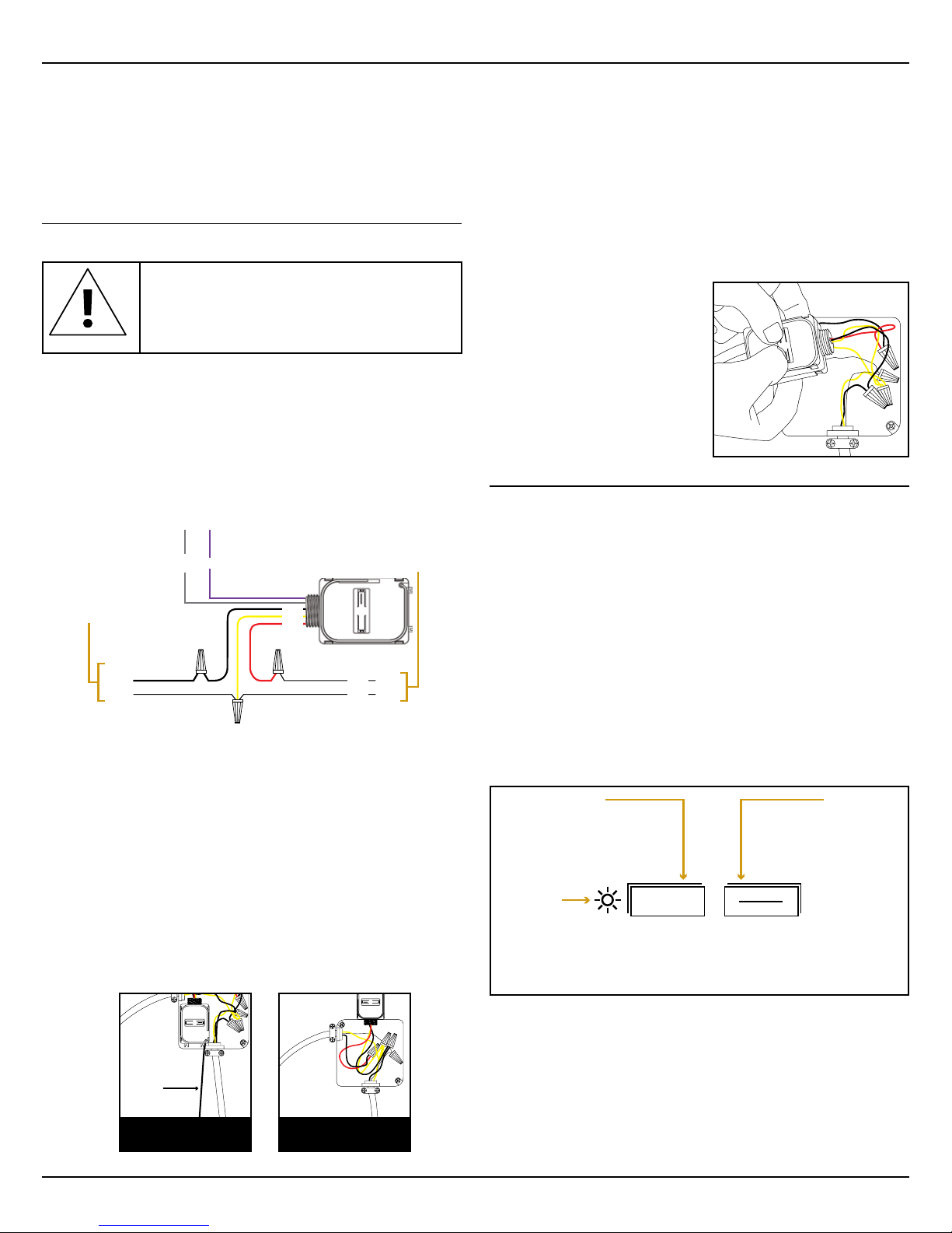
2. Identify the wiring connection at the installation site
to coordinate with the following wiring diagram.
NOTE: For display purposes, white wire is shown as yellow.
Power Input
120VAC/
277VAC
Neutral Neutral
3. Determine which of the two installation methods
is most appropriate:
A. Installed inside the electrical box.
NOTE: For best performance, remove the antenna from
its slot and elongate it outside and away from the box
and conduit. Install tubular sleeve (included) over
antenna and slide into relay housing.
B. Installed using the threaded connector:
i. Insert the threaded connector through
a ½” trade size (⅞” diameter) knockout.
ii. Thread the 5 module wires inside the electrical box
and through the lock nut.
Example:
antenna extended
in sleeve
A: Installed inside
electrical box
dark
grey
purple
+-
To Electrical Load
black
white
red
Hot
black
white
A: Installed using
thr
4. Connect the wires using wire nuts and cap any bare wires.
NOTE: After the module is linked and congured,
you can secure it in the installed location, see step 8.
5. Fold the wires neatly and either place the module in the
box or secure the threaded connector with the lock nut.
6. Position the module so that the setup interface
and antenna face forward (out).
TIP: If the RF reception is poor, use the antenna sleeve
provided to extend the antenna.
7. Restore power to the circuit.
8. Use the setup interface to
link devices and congure
settings (refer to the “Linking”
& “Conguring” sections).
Warning: Remove the
module from the electrical
box to use the setup
interface.
3) Device Conguration
The LED controller can be congured in two ways:
▪ By user input to the local setup interface
This approach is used for basic setup tasks
▪ Remotely using the remote commissioning interface
This approach is used for advanced conguration tasks
Local Setup Interface
The local setup interface has two buttons, LRN (O) and DIM.
LRN (O) has a corresponding 2-color LED (green, red). This
simple interface is used to link and unlink transmitters, to dim up
and down manually and to set the minimum dimming value.
To use the local setup interface, hold the module so both
thumbs can click the buttons without obscuring the LED.
LRN (O) button
Press short to start or end
linking/unlinking mode.
Press long (>10s) to delete all
linked transmitters.
LRN (O) LED
The LED will toggle red/green every 2 seconds,
while in linking/unlinking mode. After linking
(unlinking) a device it will stay green (red) for 4
seconds. The connected load will toggle between
10% and 90% dimming level, respectively.
When the button is pressed
shortly (<0.5s), the connected
load is switched ON/OFF. If
pressed longer, the 0-10V output
starts dimming up and down the
connected load. If pressed
output value will be stored as
minimum dimming level. When
shortly (<0.5s) pressing the button
while in learn mode, TWR-D10
will transmit a teach-in telegram.
Remote Commissioning Interface
The LED controller provides a wireless remote commissioning
interface for all commissioning tasks.
This interface allows conguring all device parameters
wirelessly using a laptop computer equipped with Navigan
Wireless Commissioner (WIS-NWC-USB), consisting of a USB
stick and software.
DIM (I) button
simultaneously with
the LRN (O) button
the current 0-10V
© 2016 Hubbell Control Solutions • www.hubbell-automation.com Page 2
Page 3

wiSTAR™ Dimming Control Module • Installation Guide
4) Linking
Linking is the process by which different devices are congured
to work with each other in a system. Sometimes this process is
also called Teach-in or Learn-in.
The LED controller can work together with two types of devices:
▪ Transmitters (switches and sensors) can provide input data
to the LED controller.
▪ Transceivers (Gateways or controllers) can exchange data
and commands with the LED controller.
There are two basic types of devices in the system; transmitters
and transceivers:
Transmitters (Transmit-only)
Transmitters are energy-harvesting devices that send RF messages to communicate a condition, level, or state. The following
transmitter types can be linked to the LED controller:
▪ Switches
▪ Occupancy Sensor
▪ Light Level Sensor (only in addition to switches and
occupancy sensors, not alone)
Transmitters can only be linked to transceivers, not to other
transmitters.
Transceivers (Transmit & Receive)
The LED controller is a transceiver. Transceivers are control-
ling devices that send as well as receive RF messages. They
also process relevant control logic, and actuate the appropriate
outputs (switching a light ON or OFF for example).
The LED controller can be linked to other transceivers if desired. The following other transceiver types are supported:
▪ Demand Response Controller
▪ Central Controller
Linking to transmitters (sensors or switches)
To link the LED controller with a transmitter, the LED controller
must be powered, within wireless range of the transmitter it is to
be linked to, and set to linking mode to accept links.
Once these conditions are met, the desired transmitter is triggered to send a special link message.
The LED Controller receives this link message and stores the
link parameters permanently so that the two devices can interact to provide a variety of intelligent control options.
time to link / unlink multiple devices. The mode will stop
after 30 seconds if no LRN (O) telegram is received.
2. For the transmitter to be linked, do one of the following
according to the type of device:
A. Sensor: click the designated link button.
B. Rocker Pad: click the “I” button (top button marked on
the switch plastic or “I” symbol on the back of the switch) 3
times quickly.
3. If the device has been linked successfully, the LRN (O) LED
will display solid green for 4 seconds. The LED controller is
now ready to accept new links.
NOTE: After a device is linked, additional learn telegrams
received in operating mode (not in linking / unlinking mode)
from that device will cause the connected load to toggle
once between 10% and 90%, if the EnableLinkChecker
parameter is set to ON.
This allows quickly checking the connection between this
device and the LED Controller.
4. For a linked transmitter to be unlinked, please use the same
action as described in point 2 above.
5. If the device has been unlinked successfully then the LRN
(O) LED will display solid red for 4 seconds and the load will
be switched to a dimming level of 10% for 4 seconds.
6. To exit linking / unlinking mode and return to normal opera-
tion, wait 30s without sending new LRN (O) telegrams, or
shortly press the LRN (O) button again.
Clear all linked transmitters
In order to clear all linked devices press and hold the LRN (O)
button for 10 seconds. After that the LRN (O) LED will display
solid red for 10 seconds.
Linking to Transceivers (gateways or controllers)
1. Set the other device into linking mode
2. Shortly press the LRN (O) button.
The LRN (O) LED starts toggling indicating that linking /
unlinking mode is active. The connected load will toggle
between 10% and 90%.
3. Shortly press the DIM (I) button. This will cause the LED
Controller to transmit a teach-in message identifying the
status message EEP used by it.
4. Shortly press the LRN (O) button again to return to normal
operation.
Setting the minimum output voltage level
Link / unlink procedure
1. Shortly press the LRN (O) button to enter linking / unlinking
mode.
The LRN (O) LED starts toggling red / green indicating that
linking / unlinking mode is active. In addition, the connected
load will toggle between 10% and 90%.
Once activated, this mode stays temporary active to provide
© 2016 Hubbell Control Solutions • www.hubbell-automation.com Page 3
It is possible to congure the minimum output voltage
(MinVoltageLevel) of the LED Controller via its button interface.
This level is typically set to avoid ickering and will be the mini-
mum level the load starts at when it is switched on. It will not be
possible to dim the output below this value.
Use the following steps to congure this minimum dimming
value:
Page 4

wiSTAR™ Dimming Control Module • Installation Guide
1. Press and hold the DIM (I) button.
The load will start dimming up and down.
2. Release the button when the desired minimum output volt-
age (dimming value) is reached.
3. Shortly press DIM (I) and LRN (O) button simultaneously to
store this value.
Double click (<0.7s) on “I” button: Light is switched ON immediately at MaxVoltageLevel (default 10.0V).
Short click (<0.7s) or double click (<0.7s) on “O” button (Bottom
button marked on switch or “O” symbol on back of switch): The light is
switched OFF, the current dimming value is stored.
Press and hold “I” or “O” button: Light is brightened or dimmed
until button is released or MinVoltageLevel / MaxVoltageLevel is
5) Operating Modes
The LED Controller supports the following operation modes
based on different types of connected devices:
Mode
Switches only
Occupancy
sensors only
Occupancy
sensors and
switches
Additional
light level
sensor
Additional
central
controller
Additional
demand
response
controller
Behavior of the different components is described in detail
subsequently.
A wide range of conguration parameters can be modied using
the remote commissioning tool Navigan Wireless Commissioner
(WIS-NWC-USB). These congurable parameters are marked
as italic in the following chapter.
Default Action Title 24
Compliance
Manual DIM or ON/OFF No
Auto ON/ Auto OFF (default Auto
OFF after 15 minutes)
Manual DIM or ON, Auto OFF
Can be congured to Auto ON / Auto
OFF via remote commissioning.
(default Auto OFF after 15 minutes)
Continuous dimming based on 5
supporting points or two level
dimming
Dimming via central controller
overriding sensor and switch input
During a demand response event
output will be reduced to the value
specied in the command.
After the demand response time out
the system will switch back to the
previous state.
No
Yes
Yes
Yes
Yes
reached.
Ramp up (RockerSwitchRampUpSpeed) and down (RockerSwitchRampDownSpeed) speeds for rocker operation are
congurable (default 20% per second).
Light can be automatically switched OFF automatically in ab-
sence of an occupancy sensor after time-out of RockerSwitchAutoOffTimer. This feature can be disabled by setting RockerSwitchAutoOffTimer = 0.
This feature is automatically disabled if an occupancy sensor is
present. In this case, automatic switch OFF of the light will be
performed based on the input from the occupancy sensor as
described below.
Occupancy Sensors Only
If at least one sensor detects motion, light is set to OccAutoOn-
Level (default 100%). If none of the sensors detects motion,
light is set to OccAutoOffLevel (default 0%), after OccAutoOffTimer (default 15min) has elapsed.
Ramp up (SensorRampUpSpeed) and ramp down (SensorRampDownSpeed) speeds are congurable (default 20% per
second).
Occupancy Sensors and Switches
Light can be switched ON / OFF manually, function as described
above. Once OccAutoOffTimer (default 15min) has elapsed the
light will be set to OccAutoOffLevel (default 0%).
Light will be automatically turned back ON at the last state, if
occupancy is detected within the OccGraceTimer period (default
45s) after an occupancy sensor Auto OFF event.
The system can also be congured (OccAutoOn) to automati-
6) Functional Behavior
cally switch ON the light. In this case if occupancy is detected
and light is off, the light is switched to OccAutoOnLevel.
0-10V Interface
The minimum output voltage is MinVoltageLevel (default 2.0V);
the maximum output voltage is MaxVoltageLevel (default
The period from switching OFF the light by a rocker until it can
be turned on again by occupancy sensor input can be set using
OccOverrideTimer (default 15 minutes).
10.0V). Dimming below MinVoltageLevel or above MaxVoltage-
Level is not possible.
Level and ramp percentage levels refer to the interval between
MinVoltageLevel (1%) and MaxVoltageLevel (100%). An output
level of 0% equals OFF state.
Light Level Sensor
WIS-IDM supports the integration of a light level sensor in an
open-loop system for daylight harvesting.
The light level sensor adjusts the light level according to incoming ambient light. The light level sensor will not switch ON the
Switches Only
Short click (<0.7s) on “I” button of the rocker switch: Light
comes ON at last dimming value stored before device was
switched off. At rst usage or after a reset, it will be switched to
MinVoltageLevel (default 2.0V).
© 2016 Hubbell Control Solutions • www.hubbell-automation.com Page 4
light by itself; therefore it works only in conjunction with rockers
or occupancy sensors in the system.
The light level sensor should be placed at a position facing the
window or skylight where it is not or only minimally inuenced
by light from the xtures.
Page 5

wiSTAR™ Dimming Control Module • Installation Guide
If a light level sensor is connected, the LED controller will by
default activate daylight harvesting with continuous open loop
dimming according to a user-dened dimming curve based on 5
congurable supporting points.
Each of these 5 supporting points denes the output light level
set by the LED controller for a specic input illumination level
reported by the light sensor.
In order to start dimming based on illumination the light must be
switched ON either via rocker switch or by an occupancy sensor
Auto ON event, depending on system conguration.
After a double click (<0.7s) on the “I” button of the light level
sensor, after brightening or dimming via “I” or “O” button or after
switch ON via occupancy sensor input, light will stay at the set
level until switched OFF manually or by an occupancy Auto OFF
event or until the LlsOverrideTimer (default 15 minutes) elapses.
Users can adapt the output level of the LED controller for the
current illumination level reported by the light level sensor.
This is achieved using a fast triple click (<0.7s) on the “I” button.
Doing so will replace the supporting point matching most closely
the current reported illumination level reported by the light level
sensor with the current light level and the current 0-10V output
level.
Doing that at different daylight levels allows dening the whole
curve. In addition these supporting points can also be cong-
ured by remote commissioning.
The light level sensor can alternatively be used to activate an
automatic switching mode between MaxVoltageLevel and MinVoltageLevel based on light intensity.
This can be achieved by conguring DaylightingMode to 2-level
via remote commissioning.
The thresholds for switching between these levels are dened
by PhotoOnThres (output will be set to MaxVoltageLevel for
reported values below this level) and PhotoOffThres (output will
be set to MinVoltageLevel for reported values above this level).
Repeater Function
The LED controller provides the option to activate a one or
two-level repeater for EnOcean radio telegrams. This function is
only available via remote commissioning.
1-level repeater: If a received telegram is a valid and original
(not yet repeated), the telegram is repeated after a random
delay.
2-level repeater: If a received telegram is valid and original or
repeated once, the telegram is repeated after a random delay.
Note: 2-level repeating function should only be activated if
really needed! Otherwise the system function can be compromised by collisions of telegrams.
be switched off completely. By setting it to 0xFFFF only event
based messages will be sent.
Central Controller
WIS-IDM can also be connected to a central controller (EEP A538-00). It supports the dimming command 0x02 of this EEP.
7) Troubleshooting
Problem Solution Checklist
The device does not
power up
The device does not
control linked load
Cannot link other
devices
The device does not
respond to wire-
less messages or
selected settings
Contains:
902 MHz: FCC: SZV-STM300U
IC: 5713A-STM300U
This device complies with part 15 of the FCC rules and Industry Canada ICES-003.
Operation is subject to the following two conditions: (1) This device may not cause harmful interference, and (2) this device must accept any interference received, including interference that may
cause undesired operation.
IMPORTANT! Any changes or modications not expressly approved by the party responsible for
compliance could void the user’s authority to operate this equipment.
• Check the wiring for errors
• Check the circuit breaker
• Use a voltage meter to conrm power
• Click the DIM (I) button to open/close
the
relay manually
• Turn off the power and then restore it
• Check if linking mode can be accessed
• Move closer to the device; it may be out
of range
• Try linking a different device
• Check for environmental conditions that
interfere with RF signals
• Verify the maximum number of devices
has not been exceeded
- 20 switches
- 10 occupancy sensors
- 1 light level sensor
- 1 central controller
- 1 demand response controller
• Check for environment or range issues
• Verify the device is linked
• Check if appropriate devices are linked
according to good system planning
• Extend the antenna to amplify the range:
remove it from the groove in the module,
and straighten it.
Status Messages
The LED controller will transmit a status message
(EEP D2-40-00) after change of its output state or after the
StatusMessageTimer has elapsed.
By setting StatusMessageTimer to 0 status messages can
© 2016 Hubbell Control Solutions • www.hubbell-automation.com Page 5
Page 6

wiSTAR™ Dimming Control Module • Installation Guide
8) Remote Commissioning Parameters
The following parameters can be set via remote commissioning,
e.g. using the Navigan tool.
Parameter
System Parameters
MinVoltageLevel
MaxVoltageLevel
0-10VRelayDelay
ModeAfterPowerLoss
StatusMessageTimer
RepeaterFunction
Enable-Debug-
Minimum 0-10V output voltage
level when light is switched ON
Maximum 0-10V output voltage
level when light is switched ON
Delay between switching the relay
on and starting to ramp up the
0-10V output
ModeAfterPowerLoss
(ON/OFF/LAST STATE)
Denes, how often status messages are transmitted (seconds, 0=off,
0xFFFF=only event based)
Denes the repeater level of the
device (OFF/1-Level/2-Level)
Enable or disable debug messages OFF
Messages
EnableLinkChecker
RockerSwitch-
RampUpSpeed
RockerSwitch
Ramp-
Enable or disable link checker
(if a learn telegram from a linked
device is received while in operat-
ing mode, the 0-10V output will
toggle once between 10% and
90%)
Ramp-up speed when change is
triggered by rocker input
Ramp-down speed when change is
triggered by rocker input
DownSpeed
RockerSwitch-
RockerSwitchAutoOffTimer 0 (disabled)
AutoOffTimer
Generic Sensor Parameters (Occupancy and Light Level)
SensorRamp-
UpSpeed
SensorRampDownSpeed
Ramp-up speed when change is
triggered by an occupancy or light
level sensor
Ramp-down speed when change is
triggered by an occupancy or light
level sensor
Description Default/
Notes
2.0V
10.0V
50ms
LAST
STAT E
0xFFFF
OFF
ON
2 0 % / s
0= No ramp
(immediate)
2 0 % / s
0= No ramp
(immediate)
20%/s
0= No ramp
(immediate)
20%/s
0= No ramp
(immediate)
Parameter
OccAutoOn
OccAutoOnLevel
OccOverrideTimer
OccAutoOffTimer
OccAutoOffLevel
OccGraceTimer
DaylightingMode
PhotoOnThres
PhotoOffThres
LEV1…5
OUT1…5
RAMP12, 23,
34, 45
LlsOverrideTimer
Description Default/
Occupancy Sensor Parameters
Denes if a signal from an occupancy sensor automatically
switches on lights (True/False)
Dimming value at which light is
switched on in case of Auto ON
event from occupancy sensor
Time before the occupancy sensor can switch the light back ON
in Auto ON Mode after the user
switched it OFF
Time after which lights will be
switched to OccAutoOffLevel in
case of no motion
Dimming value to which lights will
be dimmed after an occupancy
sensor Auto OFF timer event
If occupancy is detected within the
OccGraceTimer period after an oc-
cupancy Auto OFF event, lights are
turned back ON
Light Level Sensor Parameters
2-level or 5 point continuous daylight dimming
In case of 2-level mode, light is
switched to MaxVoltageLevel if
light level is below PhotoOnThres
In case of 2-level mode, light is
switched to MinVoltageLevel if light
level is above PhotoOffThres
Denes 5 input light levels
for open loop dimming curve
(LEV1<LEV2<...<LEV5)
Denes the LED controller output
values for the corresponding input
light levels
Ramp speeds between light levels
1 and 2, 2 and 3, 3 and 4 , 4 and 5
Time before the light level sensor
can modify the light level set by
user or occupancy sensor input
Notes
FALSE if
at least
one switch
is linked,
otherwise
TRUE
100%
15 min
15 min
0=disabled
0%
45 s
5 point
<200lux
>400lux
100, 200,
400, 600,
800 lux
100, 100%,
60%, 20%,
0%
1%/s
15 min
© 2016 Hubbell Control Solutions • www.hubbell-automation.com Page 6
72-00602
 Loading...