

Hubbell USF161210, USF121206, USF161206, USF161208, USF161606 Installation, Operation & Maintenance Data Sheet
...Page 1
HUBBELL ELECTRICAL PRODUCTS
A Division of HUBBELL INCORPORATE D (Delaware)
INSTALLATION, OPERATION &
Zone Classified Hazardous Locations
General Safety Information:
CAUTION:
death.
Technical information, advice and recommendations contained in these documents is based upon information that Killark believes to be reliable.
determine the suitability of the product for his intended use, a nd assume s all risk and lia bil it y whatsoever in conn ect ion th er ew ith.
SERIES USF JUNCTI ON BOXES
3940 Dr. Martin Luther King Drive
St. Louis, Missouri 63113 USA
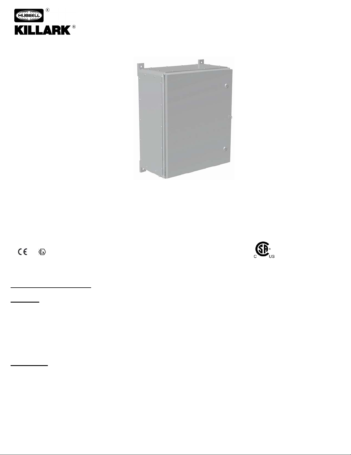
Increased Safety Terminal Enclosures For Use In
MAINTENANCE DATA SHEET
SERIES USF JUNCTION BOXES
Increased Safety Terminal Enclosures For Use
In Zone* Classified Hazardous Locations
0518 SIRA 14 ATEX 3157
IECEx SIR 14.0054
* - Suitable For Use In Division Classified Locations Based On
Equivalency - See North American Certification Ratings Below
Before installing, make sure you are compliant with area classifications, failure to do so may result in bodily injury, death and
property damage. Do not attempt installation until you are familiar with the following procedures. All installation must comply with
the applicable Electrical Code.
Make sure that the circuit is De-energized before starting installation or maintenance.
Verify that the installation is grounded. Failure to ground will create electrical shock hazards, which can cause serious injury and or
IMPORTANT:
Please read these instructions carefully before installing or maintaining this equipment. Good electrical practices should be followed
at all times and this data should be used as a guide only.
All the information and advice contained in these documents is intended for use only by persons having been trained and possessing the requisite
skill and know-how and to be used by such persons only at their own discretion and risk. The nature of these instructions is informative only and
does not cover all of the details, variations or combinations in which this equipment may be used, its storage, del iv ery , instal lation, check out, safe
operation and maintenance. Since conditions of use of the product are outside of the care, custody and control of Killark, the purchaser should
P/N KIL00921445 FORM NO. K1445 R6/18 ECO-2-045-18
Page 1 of 10
Page 2
HUBBELL ELECTRICAL PRODUCTS
A Division of HUBBELL INCORPORATE D (Delaware)
INSTALLATION, OPERATION &
Zone Classified Hazardous Locations
3940 Dr. Martin Luther King Drive
St. Louis, Missouri 63113 USA
MAINTENANCE DATA SHEET
SERIES USF JUNCTION BOXES
Increased Safety Terminal Enclosures For Use In
Application Information
a: The enclosure forms the basis for certification of a unit or protection system for use in hazardous areas other than Zone 0 (Class I Div. 1).
b: All internal components mounted in these Junction Box enclosures should be ATEX and IECEx Certified , and Listed or Recognized for
CANADA and US, for the application.
c: All components must be installed in accordance w ith the compone nt manu fac tur er' s in st a llat ion instructions.
d: A complete Junction Box should be installed using supply wiring methods (including grounding) in accordance with the
local/jurisdictional ele ctri cal code(s).
e.: A 1/4-20 UNC (M6) ground / earthing stud is supplied on all Series USF enclosures.
f: To maintian proper IP ratings, be sure to follow all mfr's. mounting instructions when installing certified cable glands or conduit entries.
Warning: Enclosures must be installed in the upright vertical position only. Mounting the enclosures in a horizontal position could cause a fire or
explosion due to excessive dust / heat build-up.
CATALOG LOGIC: USF 12 12 06 * W S 1 6 GP1234 *
1 2 3 4 5 6 7 8 9
1. SERIES DESIGNATOR
2. ENCLOSURE SIZE - L x W x D (inches)
3. MATERIAL
Blank = 316 Stainless Steel
S = 304 Stainless Steel
C = Carbon Steel (Painted)
4. TERMINAL MANUFACTURER
W = Weidmuller
A = ABB
P = Phoenix
G = WAGO
K = Klemsan Elektrik
5. TERMINAL TYPE
S = Screw
C = Cage Clamp
6. NUMBER OF ROWS (OF TERMINALS)
7. TERMINAL BLOCK SIZE
1 = 1.5 mm
4 = 4 mm
10 = 10 mm
35 = 35 mm
For Larger Sizes : Please Contact Customer Service
8. GLAND PLATE LOCATOR
0 = None 1 = Bottom 2 = LHS 3 = Top 4 = RHS
9. OPTIONS (See Catalog)
2
(#14 AWG) 2 = 2.5 mm2 (#14 AWG)
2
(#12 AWG) 6 = 6 mm2 (#10 AWG)
2
(#8 AWG) 16 = 16 mm2 (#6 AWG)
2
(#2 AWG)
P/N KIL00921445 FORM NO. K1445 R6/18 ECO-2-045-18
Page 2 of 10
Page 3
HUBBELL ELECTRICAL PRODUCTS
A Division of HUBBELL INCORPORATE D (Delaware)
INSTALLATION, OPERATION &
Zone Classified Hazardous Locations
WARNING: Enclosures that are powder co ated have a potent ial electrostatic charging hazard. Wipe the enclosure down with a moi st cloth
Terminal Block Installation and Wiring Instructions:
l: When Weidmuller WDU 1.5 or WDU 2.5 Series Terminal Blocks are installed, they are limited to a maximum current of 15A.
3940 Dr. Martin Luther King Drive
St. Louis, Missouri 63113 USA
MAINTENANCE DATA SHEET
SERIES USF JUNCTION BOXES
Increased Safety Terminal Enclosures For Use In
Enclosure and Cover Installation Instructions
before servicing.
a: Using a screwdriver with a #2 Phillips Head, a Standard Slotted or Robertson style head, remove the cover screws. Securely fasten the
enclosure to the mounting location, using up to a 1/4” (M6) diameter steel bolt and washer. The mounting location must be flat and provide
proper clearance, rigidity and strength to support the enclosure and all contained devices. Mounting dimensions are shown in this document.
b: Install Internal Components per the Mfrs. installation instructions. (See "Wiring and Terminal Block" and "Cable Gland / Conduit Entry"
Installation Instructions Sections below).
c: Grounding connections are available at the din rail, earth continuity plate and internal- external ground stud.
d: Bonding connections are available on covers and boxes of all enclosures. All exposed metal should be bonded per local electrical codes.
e: Closing / Installing the enclosure cover: Thread each cover screw half way into the threaded insert without completely tightening in a diagonal
pattern. Then complete installation of cover by tightening screws in the same diagonal pattern to a minimum torque of 3 Nm (26 lb-i ns.) to a
maximum of 4 Nm (35 lb-ins.). DO NOT OVERTIGHTEN OR USE AN IMPACT TOOL. A consistent fit over the entire length of the cover joint
should be verified at the time of installation.
f: This enclosure is provided without cable glands / conduit sealing devices. Proper selection of cable glands / conduit sealing devices must
occur in the field.
g: Cable fittings must be certified “Ex e” components per EN 60079-7. For lines which are not permanently installed, only cable fittings
appropriate for this purpose can be used. They are to be protected from loosening and locked against rotation, i.e. clips, cemented, etc., per EN
60079-7. The operating (service) temperature of the enclosure is limited to the temperature of the gland fitting if less than the enclosure.
h: Killark KDE series drain and breather may be installed. The operating temperature of the enclosure is limited to the temperature of the drain
and breathers if lower than the enclosure's. Other drain and breathers may be installed, the user is responsible for ensuring that the
protection concept, temperature class and relevant IP rating is maintained.
i: All unused conduit openings must be fitted with a certified close-up plug of equivalent minimum required IP rating as required.
a: Attention to detail is highly recommended when installing and wiring the Terminal Blocks. Proper installation is required to ensure the
component Certification Ratings are not invalidated.
b: Care should be taken not to damage or crack the DIN-Rail mounting clips when removing or installing polymeric terminal blocks. Damaged or
loose-fitting terminal blocks should be replaced before energizing the device.
c: Refer to each Terminal Block Manufacturer's Installation Instructions for suitable wire types (ie: Solid, Stranded), proper wire stripping lengths,
and terminal torques. OVERTIGHTENED or LOOSE WIRE TERMINALS MAY CAUSE OVERHEATING, WHICH CAN RESULT IN AN
ELECTRIC SHOCK OR EXPLOSION HAZARD.
d Care shall be taken to ensure proper separation of circuits (voltages), and spacings (creepage and clearance distances between live parts of
opposite polarity, and between all live parts and dead metal) are maintained. Refer to IEC/EN/UL/CSA 60079-7, Table 2, for minimum creepage
and clearance distances.
e: Grounding connections are available at the din rail, earth continuity plate and internal- external ground stud. Bonding connections are
available on covers and boxes of all enclosures. All exposed metal should be bonded per local electrical codes.
f: Wiring must be carried out in accordance with the relevant local and national electrical codes (ie: IEC/EN 60079-14, IEC/EN 61241-0 and
IEC/EN 61241-1.
g: All conductor insulation and terminal block service temperature ratings shall be suitable for (exceed) the minimum ambient and
maximum temperature (defer to T-Code) achieved in service. All conductors shall be sized per the National or Local Electrical Codes
for the max. continuous current or max. motor load of the installation.
h: Conductors at entry points may reach 73oC in a +55oC ambient, and may reach 108oC in a +90oC ambient.
i: Only the terminal blocks listed on Killark certificates may be installed in the enclosures. See Table A below.
j: No more than one conductor shall not be permitted in a wire terminal, unless the device has been evaluated specifially for multiconductor
installation (See Terminal Block Mfr's Installation Instructions). Ferrules may be used if the Terminal Block has been approved for use with Solid
Wires of equivalent diameter.
k: When installing Terminal blocks, the maximum voltage, current and dissipated power shown on the Junction Box nameplate must not be
exceeded.
P/N KIL00921445 FORM NO. K1445 R6/18 ECO-2-045-18
Page 3 of 10
Page 4

HUBBELL ELECTRICAL PRODUCTS
A Division of HUBBELL INCORPORATE D (Delaware)
INSTALLATION, OPERATION &
Zone Classified Hazardous Locations
Minimum Ambient "Ta"
When Installed
KEMA 97ATEX2755U
-50oC
ABB
ZK
Cage clamp
LCIE 13ATEX3042U
IECEx LCI 13.0025U
-50oC
-50oC
-50oC
-50oC
-50oC
-50oC
KEMA 98ATEX1786U
IECEx KEM 06.0029U
KEMA 04ATEX2048U
IECEx KEM 06.0027U
IECEx PTB
10.0046U
TABLE A: Terminal Blocks Approved For Use in USF Junction Boxes
3940 Dr. Martin Luther King Drive
St. Louis, Missouri 63113 USA
MAINTENANCE DATA SHEET
SERIES USF JUNCTION BOXES
Increased Safety Terminal Enclosures For Use In
Manufacturer Series Style ATEX Certificate IECEx Certificate
Weidmuller WDU Screw KEMA 98ATEX1683U N/A
KEMA 01ATEX2186U
Weidmuller WDU Screw
KEMA 08ATEX0014U
KEMA 98ATEX1686U
KEMA 99ATEX6545U
SIRA 02ATEX3153U
SIRA 02ATEX3242
IECEx SIR
05.0040U IECEx SIR
05.0039U
IECEx ULD 05.0008U
SIRA 02ATEX3242U
Weidmuller ZDU Cage clamp KEMA 97ATEX4677U N/A
IECEx ULD
05.0009U IECEx KEM
07.0061U IECEx KEM
06.0048U
Weidmuller ZDU Cage clamp
KEMA 99ATEX5514U
KEMA 97ATEX2521U
KEMA 01ATEX2106U
KEMA 00ATEX2107U
Weidmuller PDU Spring (push in) KEMA 06ATEX0177U IECEx KEMA 06.0032U
Klemsan Elektrik AVK Screw FTZU 10ATEX0071U IECEx FTZU 10.0012U
Klemsan Elektrik MVK Screw FTZU 09ATEX0252U IECEx FTZU 10.0011U
Klemsan Elektrik PIK Screw FTZU 09ATEX0252U IECEx FTZU 10.0011U
Klemsan Elektrik PUK Screw FTZU 09ATEX0252U IECEx FTZU 10.0011U
Klemsan Elektrik PYK Cage clamp FTZU 09ATEX0252U IECEx FTZU 10.0011U
ABB ZS Screw LCIE 08ATEX0007U IECEx LCI 08.0031U
of Overall Junction Box
o
-50
C
o
C
-50
-50oC
o
C
-50
o
(-40
C for devices
covered by Cert. Number
KEMA 01ATEX2106U)
o
C
-20
o
-50
C
o
-50
C
o
C
-50
o
-50
C
-50oC
WAGO 2001-**** Cage clamp PTB 05ATEX1094U IECEx PTB 11.0093U
WAGO 2002-**** Cage clamp PTB 03ATEX1162U IECEx PTB 03.004U
WAGO 2004-**** Cage clamp PTB 05ATEX1095U IECEx PTB 05.0033U
WAGO 2006-**** Cage clamp PTB 05ATEX1030U IECEx PTB 05.0014U
WAGO 2010-**** Cage clamp PTB 05ATEX1070U IECEx PTB 06.0003U
WAGO 2016-**** Cage clamp PTB 05ATEX1031U IECEx PTB 05.0015U
Phoenix UKH Screw
Phoenix UT Screw
Phoenix PT Push in
Phoenix ST Cage clamp
Phoenix QT Cage clamp
Phoenix UK Screw
KEMA 99ATEX8332U
KEMA 06ATEX0017U
PTB 09ATEX1111U
PTB 09ATEX1112U
KEMA 01ATEX2129U
KEMA 00ATEX2052U
KEMA 01ATEX2260U
KEMA 04ATEX2226U
KEMA 03ATEX2557U
KEMA 05ATEX2148U
KEMA 96ATEX4370U
KEMA 06ATEX0119U
KEMA 98ATEX1651U
KEMA 98ATEX1786U
KEMA 99ATEX4487 U
KEMA 96ATEX4370U
IECEx KEM 06.0030U
IECEx KEM 06.0013U
10.0021U IECEx KEM
IECEx KEM 06.0051U
IECEx KEM 06.0050U
IECEx KEM 06.0033U
IECEX KEM 06.0043U
IECEx KEM 07.0015U
IECEx KEM 07.0010U
IECEx KEM
06.0034U IECEx KEM
06.0029U IECEX KEM
06.0035U
-50oC
-50oC
-50oC
-50oC
o
-50
o
-45
o
-50
C
C
C
P/N KIL00921445 FORM NO. K1445 R6/18 ECO-2-045-18
Page 4 of 10
Page 5

HUBBELL ELECTRICAL PRODUCTS
A Division of HUBBELL INCORPORATE D (Delaware)
INSTALLATION, OPERATION &
Zone Classified Hazardous Locations
WARNING: Before servicing the enclosure, be sure ALL electrical power is OFF and LOCKED OUT.
WARNING: Enclosures that are powder coated have a potential electrostatic charging hazard. Wipe the enclosure down
3940 Dr. Martin Luther King Drive
St. Louis, Missouri 63113 USA
MAINTENANCE DATA SHEET
SERIES USF JUNCTION BOXES
Increased Safety Terminal Enclosures For Use In
Maintenance Instructions:
WARNING: Enclosures that are powder coated have a potential electrostatic charging hazard. Wipe the enclosure down
with a moist cloth before servicing.
WARNING: Maintenance on the end product should be carried out by authorized and trained personnel only. Following
any maintenance, the enclosure gasket must be checked for damage before the cover is replaced / reinstalled.
a: After initial installation, the unit should be inspected at regular intervals to verify the cover is tight; that all conduit or gland
connections are intact and free of corrosion and that the enclosure mounting bolts are tight and in good condition.
b: Inspect flanged surfaces of the box and of the cover gasket. Surfaces must be free of nicks, dirt or any foreign particle build-up
that would prevent a proper seal. Check hinges to ensure they are improper working order.
c: Should the surfaces be damaged, consult factory. Never attempt to rework the surfaces in the field. Surfaces must seat fully
against each other to provide the proper joint.
d: Apply a light coating of Killark “LUBG” lubricant to the box flange before closing the cover. All cover screws must be installed
tightly (25 to 36 lb-ins.) to ensure the joint between the box and cover is sealed prior to powering the unit. An improper joint can
result in an explosion with the possibility of physical injury and property damage.
e: Series USF hinged covers are permanent and are not field removable or replaceable. Prior to securing the cover add lubrication
to the hinge pin to aid in operation and the free movement of the cover . Important: Care is to be taken opening the cover to help
prevent accidental damage to the cover and cover gasket. Never apply excess force to the cover when closing the hinged cover.
Never hammer the cover, this will deform the covers and possibly reduce the protection level of the enclosure.
Conditions For Safe Use (IECEx/ATEX):
with a moist cloth before servicing. Conductors at entry points may reach 73oC in a +55oC ambient, and may reach 108oC
in a +90
a: The range of enclosures shall only be used in a service temperature range of -55 OC to +135 OC.
b: When Junction Boxes are equipped by the manufacturer with wired terminals, a routine electric strength test is required per EN
60079, Clause 6.1.
c: The maximum dissipated power in watts for each model of junction box shall be calculated in accordance with EN 60079-7,
Annex E, E.2, and shall not exceed the maximums given in Table 6 below.
o
C ambient.
P/N KIL00921445 FORM NO. K1445 R6/18 ECO-2-045-18
Page 5 of 10
Page 6

HUBBELL ELECTRICAL PRODUCTS
A Division of HUBBELL INCORPORATE D (Delaware)
INSTALLATION, OPERATION &
Zone Classified Hazardous Locations
To maintain the IP (Ingress Protection) levels and the NEMA / TYPE ratings of the Series USF enclosures, end-product nameplates or label & tag
3940 Dr. Martin Luther King Drive
St. Louis, Missouri 63113 USA
Certification Information
MAINTENANCE DATA SHEET
SERIES USF JUNCTION BOXES
Increased Safety Terminal Enclosures For Use In
North American Certifications:
North American (NEC/CEC) Certificat ions***:
Class I, Zone 1 AEx eb IIC Gb T6...T4 (U.S.)
Zone 21 AEx tb IIIC Db T80 oC...T130 oC IP66 (U.S.)
Ex db eb IIC Gb T6...T4 (CAN)
Ex tb IIIC Db T85
Class I, Division 2, Groups A,B,C,D
Class II, Zone 21 & 22
Class II, Groups E, F, G; Class III
Type 3/4/4X**/IP66
** - Only 304 and 316 Stainless Steel Enclosures are Type 4X
o
C ≤ Ta ≤ +40oC (when marked T6 / T80oC)
- 50
o
C ≤ Ta ≤ +55oC (when marked T5 / T100oC)
- 50
o
C ≤ Ta ≤ +90oC (when marked T4 / T130oC)
- 50
Standards Applied:
CSA 60079-0 ANSI/ISA 60079-0
CSA 60079-7 ANSI/ISA 60079-7
CSA 60079-31 ANSI/ISA 60079-31
CSA No. 94.1 / 94.2 / 14 UL50 / UL50E / UL508
CSA 60529 ANSI/IEC 60529
o
C...T135 oC IP66 (CAN)
IEC / ATEX Certifications:
ATEX Ratings: SIRA 14 ATEX 3157
0518 II 1 G Ex ia IIC T6/T5/T4 Ga
II 2 D Ex tb IIIC T80
0518 II 2 G Ex eb IIC T6/T5/T4 Gb
Ex ib IIC T6/T5/T4 Gb
II 2 D Ex tb IIIC T80
0518 II 1 G Ex eb ib IIC T6/T5/T4 Gb
II 2 D Ex tb IIIC T80
IECEx Ratings: IECEx SIR 14.0054
When ia Terminals are installed (only):
Ex ia IIC T6/T5/T4 Ga
Ex tb IIIC T80
Ex eb IIC T6/T5/T4 Gb
Ex ib IIC T6/T5/T4 Gb
Ex tb IIIC T80
Ex eb ib IIC T6/T5/T4 Gb
Ex tb IIIC T80
o
- #
C ≤ Ta ≤ +40oC (when marked T6 / T80oC)
o
- #
C ≤ Ta ≤ +55oC (when marked T5 / T100oC)
o
- #
C ≤ Ta ≤ +90oC (when marked T4 / T130oC)
# - Mimumum Ambient Temp. may be either -50oC, -45oC, -40oC or -20oC - See Table
1 below for minimum ambient ratings based on installed T-Blocks.
Standards Applied:
EN 60079-0 IEC 60079-0
EN 60079-7 IEC 60079-7
EN 60079-11 IEC 60079-11 (Terminal Blocks)
IEC 60079-31
o
C / T100oC / T130oC Db IP66
o
C / T100oC / T130oC Db IP66
o
C / T100oC / T130oC Db IP66
o
C / T100oC / T130oC Db IP66
(with Ex e terminals only) OR
o
C / T100oC / T130oC Db IP66
o
C / T100oC / T130oC Db IP66
(with Ex ib terminals only)
(with Ex e & ib terminals)
OR
OR
OR
OR
Electrical Ratings
The overall electrical ratings of an USF Junction Box is dependent upon the ratings of the terminal blocks installed. Please refer to the Terminal
Block Mfr's. website - or see the Killark Online Catalog (Section E) for specific Terminal Block Current, Voltage and Resistance (Full and
Partial Load Wattage) ratings:
http://ecatalog.hubbell-killark.com/
Labels / Nameplates
mounting holes must not penetrate the interior of the enclosure.
Earthing (Grounding)
The earth connection accepts a cable lug. The cable must be run and fixed near to the enclosure. The earth connection must be made in all
circumstances.
Conduit Hubs and Cable Glands
Conduit hubs and cable gland sizes may be mixed. The maximum number of hubs or cabl e glands must be selected such that the walls are not weakened
nor the enclosure stability affected .
See Figure 1 below, a nd Tables 1 - 7 below for Enclosure Dimensions and Mounting Hole Loc ations, Conduit and Gland Mountnig Details (Useable Wall
Area, Hole Spacing D etails, etc) .
P/N KIL00921445 FORM NO. K1445 R6/18 ECO-2-045-18
Page 6 of 10
Page 7

HUBBELL ELECTRICAL PRODUCTS
A Division of HUBBELL INCORPORATE D (Delaware)
INSTALLATION, OPERATION &
Zone Classified Hazardous Locations
NPT
(Metric)
2-1/2"
(M63)
1-1/2" (
M40)
1-1/4"
(M32)
3/4"
(M20)
1/2"
(M16)
1-5/8
(41)
1-1/4
(32)
NPT
(Metric)
2-1/2"
(M63)
1-1/4"
(M32)
3/4"
(M20)
1/2"
(M16)
2-1/8
(54)
1-3/4
(44)
1-1/2
(38)
1-1/4
(32)
Size
(mm2)
IN.
(mm)
5.5
(140)
6.5
(164)
NPT
4"
3-1/2"
3"
2-1/2"
2"
1-1/2
1-1/4"
1"
3/4"
1/2"
Max. Hole
Dia. IN. (mm)
4.53
(115.06)
4.03
(102.36)
3.53
(89.66)
2.905
(73.79)
2.405
(61.08)
1.93
(49.2)
1.69
(42.93)
1.345
(34.16)
.87
(22.09)
Metric
M100
M80
M75
M63
M50
M40
M32
M25
M20
M16
Max. Hole
Dia. mm (IN.)
100.7
(3.94)
80.7
(3.15)
75.7
(2.95)
63.7
(2.48)
50.7
(1.97)
40.7
(1.58)
32.7
(1.26)
25.7
(0.98)
16.7
(0.63)
3940 Dr. Martin Luther King Drive
St. Louis, Missouri 63113 USA
MAINTENANCE DATA SHEET
SERIES USF JUNCTION BOXES
Increased Safety Terminal Enclosures For Use In
TABLE 1 - Minimum Distance - From Edge of Enclosure to Center of Conduit / Cable Entry
4" 3-1/2" 3" (M75)
2" (M50)
1" (M25)
IN. (mm) 2-3/4 (70) 2-1/2 (64) 2 (51) 2 (51)
1-3/8 (35)
1 (25) 7/8 (22) 3/4 (19)
TABLE 2 - Minimum Distance - From Edge of Gland Plate to Center of Conduit / Cable Entry
4" 3-1/2" 3" (M75)
2" (M50) 1-1/2" (M40)
1" (M25)
IN. (mm) 3-1/4 (83) 3 (76) 2-3/4 (70) 2-1/2 (64)
1-7/8 (48)
1-3/8 (35)
TABLE 3 - CEC / NEC Minimum Wire Bending Space - From Inside Wall of Enclosure (North America Applications Only)
AWG
16 (1.5) 14 (2.5) 12 (4) 10 (6) 8 (10) 6 (16) 4 (25) 2 (35) 1/0 (50) 2/0 (70) 3/0 (95)
1.5 (38) 1.5 (38) 1.5 (38) 1.5 (38) 1.5 (38) 2 (51) 3 (76) 3.5 (89)
6 (152)
4/0
(120)
7 (178)
TABLE 4 - Conduit / Cable Gland Hole Diameters - For additional sizes, please contact Customer Service
1.08 (27.4)
20.7 (0.79)
TABLE 5 - Minimum Distance - From Center Line to Center Line of Conduit / Cable Entries
P/N KIL00921445 FORM NO. K1445 R6/18 ECO-2-045-18
Page 7 of 10
Page 8

HUBBELL ELECTRICAL PRODUCTS
A Division of HUBBELL INCORPORATE D (Delaware)
INSTALLATION, OPERATION &
Zone Classified Hazardous Locations
3940 Dr. Martin Luther King Drive
St. Louis, Missouri 63113 USA
MAINTENANCE DATA SHEET
SERIES USF JUNCTION BOXES
Increased Safety Terminal Enclosures For Use In
FIGURE 1 - USF (HINGED COVER) - (See Table 6 and 7 below)
Note: The maximum hole size for enclosure depths of 6" (153mm) through 20" (508mm) and with
blank walls is a 4" NPT (M100). The maximum hole size for enclosure with a depths of 6"
(153mm) and with gland plate cut outs is 3"N PT (M75). The maximum hole size for enclosure
depths of 8" (203mm) through 20" (508mm) and with gland plate cut outs is 4" NPT (M100).
P/N KIL00921445 FORM NO. K1445 R6/18 ECO-2-045-18
Page 8 of 10
Page 9

HUBBELL ELECTRICAL PRODUCTS
INSTALLATION, OPERATION &
Zone Classified Hazardous Locations
when using
Terminals
when using
Terminals
Catalog
Number
USF121206 12 (305) 12 (305) 6 (153) 10.69 (272) 10.69 (272) 13.63 (346) 13.63 (346) 15.0 7.5
USF161206 16 (407) 12 (305) 6 (153) 10.69 (272) 14.69 (373) 13.63 (346) 17.63 (448) 17.0 8.5
USF161208 16 (407) 12 (305) 8 (203) 10.69 (272) 14.69 (373) 13.63 (346) 17.63 (448) 20.6 10.3
USF161210 16 (407) 12 (305) 10 (254) 10.69 (272) 14.69 (373) 13.63 (346) 17.63 (448) 23.5 11.7
USF161606 16 (407) 16 (407) 6 (153) 14.69 (373) 14.69 (373) 17.63 (448) 17.63 (448) 19.0 9.5
USF161608 16 (407) 16 (407) 8 (203) 14.69 (373) 14.69 (373) 17.63 (448) 17.63 (448) 20.0 10.0
USF161610 16 (407) 16 (407) 10 (254) 14.69 (373) 14.69 (373) 17.63 (448) 17.63 (448) 25.0 12.5
USF201606 20 (508) 16 (407) 6 (153) 18.69 (475) 14.69 (373) 21.63 (549) 17.63 (448) 21.0 10.5
USF201608 20 (508) 16 (407) 8 (203) 14.69 (373) 18.69 (475) 17.63 (448) 21.63 (549) 23.0 11.5
USF201610 20 (508) 16 (407) 10 (254) 14.69 (373) 18.69 (475) 17.63 (448) 21.63 (549) 26.0 13.0
USF202006 20 (508) 20 (508) 6 (153) 14.69 (373) 18.69 (475) 17.63 (448) 21.63 (549) 24.3 12.1
USF202008 20 (508) 20 (508) 8 (203) 18.69 (475) 18.69 (475) 21.63 (549) 21.63 (549) 26.0 13.0
USF202010 20 (508) 20 (508) 10 (254) 18.69 (475) 18.69 (475) 21.63 (549) 21.63 (549) 30.0 15.0
USF202012 20 (508) 20 (508) 12 (305) 18.69 (475) 18.69 (475) 21.63 (549) 21.63 (549) 36.0 18.0
USF241606 24 (610) 16 (407) 6 (153 14.69 (373) 22.69 (576) 17.63 (448) 25.63 (651) 23.0 11.5
USF241608 24 (610) 16 (407) 8 (203) 18.69 (475) 18.69 (475) 21.63 (549) 21.63 (549) 23.0 11.5
USF241610 24 (610) 16 (407) 10 (254) 14.69 (373) 22.69 (576) 17.63 (448) 25.63 (651) 31.0 15.5
USF242006 24 (610) 20 (508) 6 (153) 14.69 (373) 22.69 (576) 17.63 (448) 25.63 (651) 24.5 12.2
USF242008 24 (610) 20 (508) 8 (203) 18.69 (475) 22.69 (576) 21.63 (549) 25.63 (651) 31.5 15.7
USF242010 24 (610) 20 (508) 10 (254) 18.69 (475) 22.69 (576) 21.63 (549) 25.63 (651) 33.6 16.8
USF242012 24 (610) 20 (508) 12 (305) 18.69 (475) 22.69 (576) 21.63 (549) 25.63 (651) 36.0 18.0
USF242406 24 (610) 24 (610) 6 (153) 18.69 (475) 22.69 (576) 21.63 (549) 25.63 (651) 25.8 12.9
USF242408 24 (610) 24 (610) 8 (203) 22.69 (576) 22.69 (576) 25.63 (651) 25.63 (651) 34.0 17.0
USF242410 24 (610) 24 (610) 10 (254) 22.69 (576) 22.69 (576) 25.63 (651) 25.63 (651) 34.0 17.0
USF242412 24 (610) 24 (610) 12 (305) 22.69 (576) 22.69 (576) 25.63 (651) 25.63 (651) 38.0 19.0
USF242416 24 (610) 24 (610) 16 (407) 22.69 (576) 22.69 (576) 25.63 (651) 25.63 (651) 42.0 21.0
USF242420 24 (610) 24 (610) 20 (508) 22.69 (576) 22.69 (576) 25.63 (651) 25.63 (651) 57.3 28.6
USF302008 30 (762) 20 (508) 8 (203) 22.69 (576) 22.69 (576) 25.63 (651) 25.63 (651) 36.5 18.2
USF302010 30 (762) 20 (508) 10 (254) 18.69 (475) 28.69 (729) 21.63 (549) 31.63 (803) 36.0 18.0
USF302408 30 (762) 24 (610) 8 (203) 18.69 (475) 28.69 (729) 21.63 (549) 31.63 (803) 39.0 19.5
USF302410 30 (762) 24 (610) 10 (254) 22.69 (576) 28.69 (729) 25.63 (651) 31.63 (803) 38.0 19.0
USF302412 30 (762) 24 (610) 12 (305) 22.69 (576) 28.69 (729) 25.63 (651) 31.63 (803) 40.0 20.0
USF302420 30 (762) 24 (610) 20 (508) 22.69 (576) 28.69 (729) 25.63 (651) 31.63 (803) 57.3 28.6
USF303008 30 (762) 30 (762) 8 (203) 22.69 (576) 28.69 (729) 25.63 (651) 31.63 (803) 43.0 21.5
USF303010 30 (762) 30 (762) 10 (254) 28.69 (729) 28.69 (729) 31.63 (803) 31.63 (803) 40.0 20.0
USF303012 30 (762) 30 (762) 12 (305) 28.69 (729) 28.69 (729) 31.63 (803) 31.63 (803) 46.0 23.0
USF362408 36 (915) 24 (610) 8 (203) 34.69 (881) 28.69 (729) 37.63 (956) 31.63 (803) 44.0 22.0
USF362410 36 (915) 24 (610) 10 (254) 9.79 (249) 35.20 (894) 8.15 (207) 27.63 (702) 40.0 20.0
Height
in. (mm)
A Division of HUBBELL INCORPORATE D (Delaware)
3940 Dr. Martin Luther King Drive
St. Louis, Missouri 63113 USA
TABLE 6 - USF OVERALL DIMENSION CHART
Width Depth
"E"
"F" "G" "H"
MAINTENANCE DATA SHEET
SERIES USF JUNCTION BOXES
Increased Safety Terminal Enclosures For Use In
Max. Power Dissipation (W)
Screw Type
Cage Clamp
P/N KIL00921445 FORM NO. K1445 R6/18 ECO-2-045-18
Page 9 of 10
Page 10

HUBBELL ELECTRICAL PRODUCTS
A Division of HUBBELL INCORPORATE D (Delaware)
INSTALLATION, OPERATION &
Zone Classified Hazardous Locations
Catalog
Number
"A" Gland
Plate
"B" Gland
Plate
"C" Gland
Plate
"A" Blank
Wall Area
"B" Blank
Wall Area
"C" Blank
Wall Area
USF121206
5.79 (147)
11.20 (284)
5.79 (147)
11.75 (298)
35.2 (894)
11.2 (284)
USF161206
5.79 (147)
15.20 (386)
5.79 (147)
11.75 (298)
35.2 (894)
11.2 (284)
USF161208
7.79 (198)
15.20 (386)
7.79 (198)
11.75 (298)
35.2 (894)
11.2 (284)
USF161210
9.79 (249)
15.20 (386)
9.79 (249)
11.75 (298)
35.2 (894)
11.2 (284)
USF161606
5.79 (147)
15.20 (386)
5.79 (147)
11.75 (298)
35.2 (894)
15.2 (386)
USF161608
7.79 (198)
15.20 (386)
7.79 (198)
11.75 (298)
35.2 (894)
15.2 (386)
USF161610
9.79 (249)
15.20 (386)
9.79 (249)
11.75 (298)
35.2 (894)
15.2 (386)
USF201606
5.79 (147)
15.20 (386)
5.79 (147)
11.75 (298)
35.2 (894)
19.2 (488)
USF201608
5.79 (147)
19.20 (488)
5.79 (147)
11.75 (298)
35.2 (894)
15.2 (386)
USF201610
7.79 (198)
19.20 (488)
7.79 (198)
11.75 (298)
35.2 (894)
15.2 (386)
USF202006
9.79 (249)
19.20 (488)
9.79 (249)
11.75 (298)
35.2 (894)
15.2 (386)
USF202008
5.79 (147)
19.20 (488)
5.79 (147)
11.75 (298)
35.2 (894)
19.2 (488)
USF202010
7.79 (198)
19.20 (488)
7.79 (198)
11.75 (298)
35.2 (894)
19.2 (488)
USF202012
9.79 (249)
19.20 (488)
9.79 (249)
11.75 (298)
35.2 (894)
19.2 (488)
USF241606
11.79 (299)
19.20 (488)
5.79 (147)
11.75 (298)
35.2 (894)
11.2 (284)
USF241608
11.79 (299)
19.20 (488)
11.79 (299)
11.75 (298)
35.2 (894)
15.2 (386)
USF241610
7.79 (198)
23.20 (589)
7.79 (198)
11.75 (298)
35.2 (894)
15.2 (386)
USF242006
9.79 (249)
23.20 (589)
9.79 (249)
11.75 (298)
35.2 (894)
19.2 (488)
USF242008
5.79 (147)
23.20 (589)
5.79 (147)
11.75 (298)
35.2 (894)
19.2 (488)
USF242010
7.79 (198)
23.20 (589)
7.79 (198)
11.75 (298)
35.2 (894)
19.2 (488)
USF242012
9.79 (249)
23.20 (589)
9.79 (249)
11.75 (298)
35.2 (894)
19.2 (488)
USF242406
11.79 (299)
23.20 (589)
11.79 (299)
11.75 (298)
35.2 (894)
23.2 (589)
USF242408
5.79 (147)
23.20 (589)
5.79 (147)
11.75 (298)
35.2 (894)
23.2 (589)
USF242410
7.79 (198)
23.20 (589)
7.79 (198)
11.75 (298)
35.2 (894)
23.2 (589)
USF242412
9.79 (249)
23.20 (589)
9.79 (249)
11.75 (298)
35.2 (894)
23.2 (589)
USF242416
11.79 (299)
23.20 (589)
11.79 (299)
11.75 (298)
35.2 (894)
23.2 (589)
USF242420
15.79 (401)
23.20 (589)
15.79 (401)
11.75 (298)
35.2 (894)
23.2 (589)
USF302008
19.79 (503)
23.20 (589)
19.79 (503)
11.75 (298)
35.2 (894)
19.2 (488)
USF302010
7.79 (198)
29.20 (742)
7.79 (198)
11.75 (298)
35.2 (894)
19.2 (488)
USF302408
9.79 (249)
29.20 (742)
9.79 (249)
11.75 (298)
35.2 (894)
23.2 (589)
USF302410
7.79 (198)
29.20 (742)
7.79 (198)
11.75 (298)
35.2 (894)
23.2 (589)
USF302412
9.79 (249)
29.20 (742)
9.79 (249)
11.75 (298)
35.2 (894)
23.2 (589)
USF302420
11.79 (299)
29.20 (742)
11.79 (299)
11.75 (298)
35.2 (894)
23.2 (589)
USF303008
19.79 (503)
29.20 (742)
19.79 (503)
11.75 (298)
35.2 (894)
29.2 (742)
USF303010
7.79 (198)
29.20 (742)
7.79 (198)
11.75 (298)
35.2 (894)
29.2 (742)
USF303012
9.79 (249)
29.20 (742)
9.79 (249)
11.75 (298)
35.2 (894)
29.2 (742)
USF362408
11.79 (299)
29.20 (742)
11.79 (299)
11.75 (298)
35.2 (894)
23.2 (589)
USF362410
7.79 (198)
35.20 (894)
7.79 (198)
11.75 (298)
35.2 (894)
23.2 (589)
3940 Dr. Martin Luther King Drive
St. Louis, Missouri 63113 USA
MAINTENANCE DATA SHEET
SERIES USF JUNCTION BOXES
Increased Safety Terminal Enclosures For Use In
TABLE 7 - USABLE WALL AREA - DIMENSIONS
P/N KIL00921445 FORM NO. K1445 R6/18 ECO-2-045-18
Page 10 of 10
 Loading...