

Page 1
HUBBELL ELECTRICAL PRODUCTS
A Division of HUBBELL INCORPORATE D (Delaware)
INSTALLATION, OPERATION &
Drilling and Tapping Instructions For Conduit Openings
General Safety Information:
CAUTION:
Technical information, advice and recommendations contained in these documents is based upon information that Killark believes to be reliable.
determine the suitability of the product for his intended use, and assumes all risk and liability whatsoever in connection therewith.
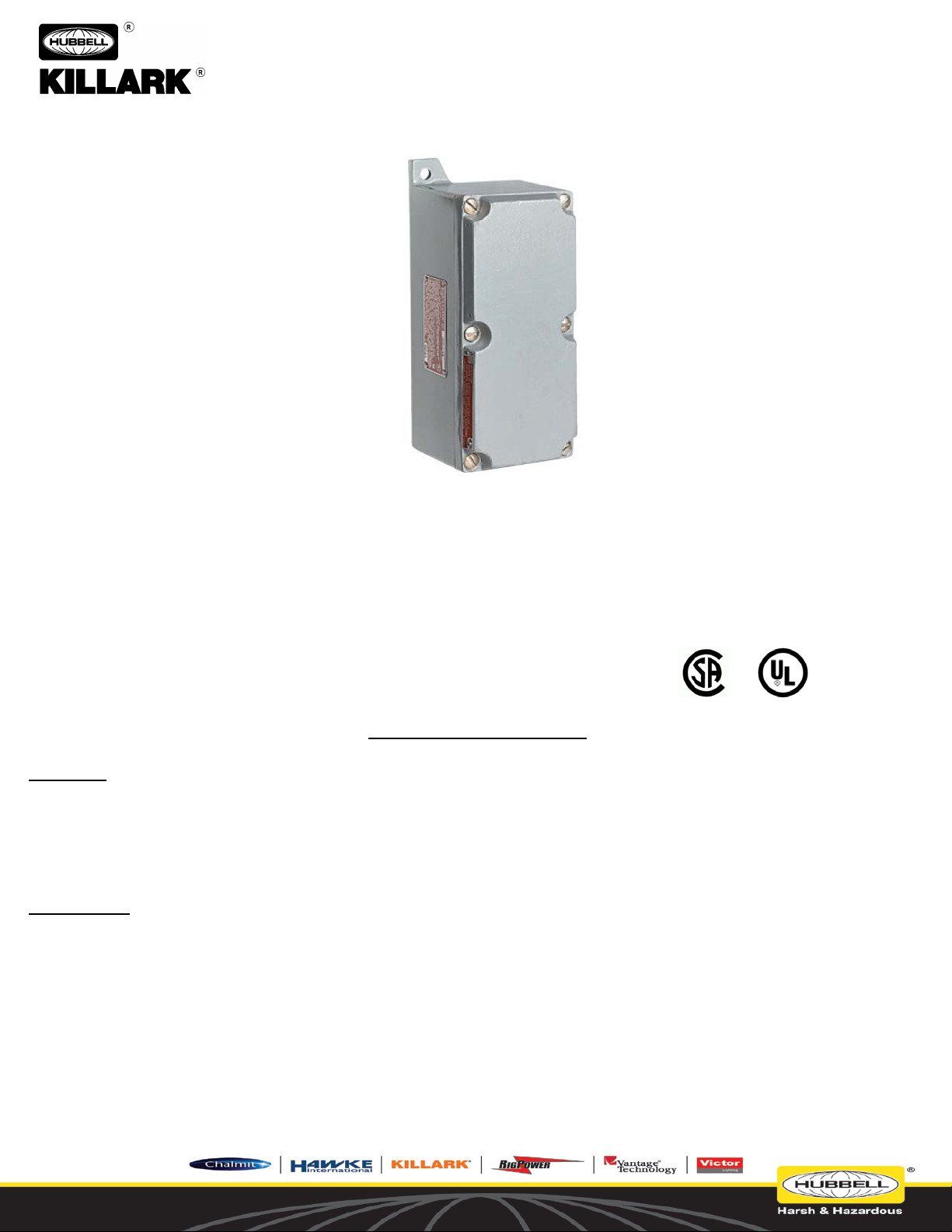
SERIES SWBC CAST ALUMINUM ENCLOSURES
3940 Dr. Martin Luther King Drive
St. Louis, Missouri 63113 USA
MAINTENANCE DATA SHEET
SERIES SWBC EMPTY ENCLOSURES
For Use In Hazardous Locations
For Use In Classified Hazardous Locations –
Instructions For Drilling and Tapping of Conduit Entries
Before installing, make sure you are compliant with area classifications, failure to do so may result in bodily injury, death and property damage.
Do not attempt installation until you are familiar with the following procedures. All installation must comply with the applicable Electrical Code.
Make sure that the circuit is De-energized before starting installation or maintenance.
Verify that the installation is grounded. Failure to ground will create electrical shock hazards, which can cause serious injury and or deat h.
IMPORTANT:
Please read these instructions carefully before installing or maintaining this equipment. Good electrical practices should be followed
at all times and this data should be used as a guide only.
All the information and advice contained in these documents is intended for use only by persons having been trained and possessing the requisite
skill and know-how and to be used by such persons only at their own discretion and risk. The nature of these instructions is informative only and
does not cover all of the details, variations or combinations in which this equipment may be used, its storage, delivery, installation, check out, safe
operation and maintenance. Since conditions of use of the product are outside of the care, custody and control of Killark, the purchaser should
P/N 00911459 FORM NO. K1022 R8/18 ECO-3-038-18
Page 1 of 3
Page 2
HUBBELL ELECTRICAL PRODUCTS
A Division of HUBBELL INCORPORATE D (Delaware)
INSTALLATION, OPERATION &
Drilling and Tapping Instructions For Conduit Openings
(10) If insufficient wall thickness is encountered, contact Killark Customer Service at 314-531-8839.
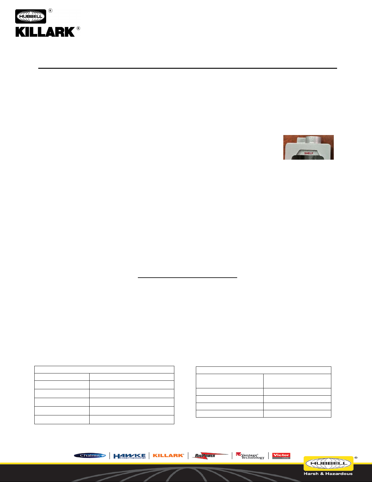
TABLE A
Cat No.
Maximum Conduit Size
SWBC-13
1-1/4 “
SWBC-14
1-1/4 “
SWBC-15
1-1/4 “
SWBC-16
1-1/4 “
SWBC-83
1-1/4 “
TABLE B – Recommended Tap Drill
TAPPED HOLE SIZE
- NPT
TAP DRILL SIZE
(Diameter)
½” – 14
23/32”
¾” – 14
59/64”
1” – 11-1/2
1-5/32”
1-1/4” – 11-1/2
1-12”
3940 Dr. Martin Luther King Drive
St. Louis, Missouri 63113 USA
MAINTENANCE DATA SHEET
SERIES SWBC EMPTY ENCLOSURES
For Use In Hazardous Locations
GENERAL INSTRUCTIONS AND REQUIREMENTS FOR DRILLING AND TAPPING IN THE FIELD
WARNING: The following requirements must be met in order to comply with the applicable UL and CSA HazLoc Standards, the National
Electrical Codes (NEC and CEC), and in order to maintain the Listing/Classification of the enclosure.
(1) Standard NPT threads (with a ¾ inch-per-foot taper) must be used for all conduit openings.
(2) Field drilling and tapping of the side and back walls of blank boxes may be performed provided the location of the conduit
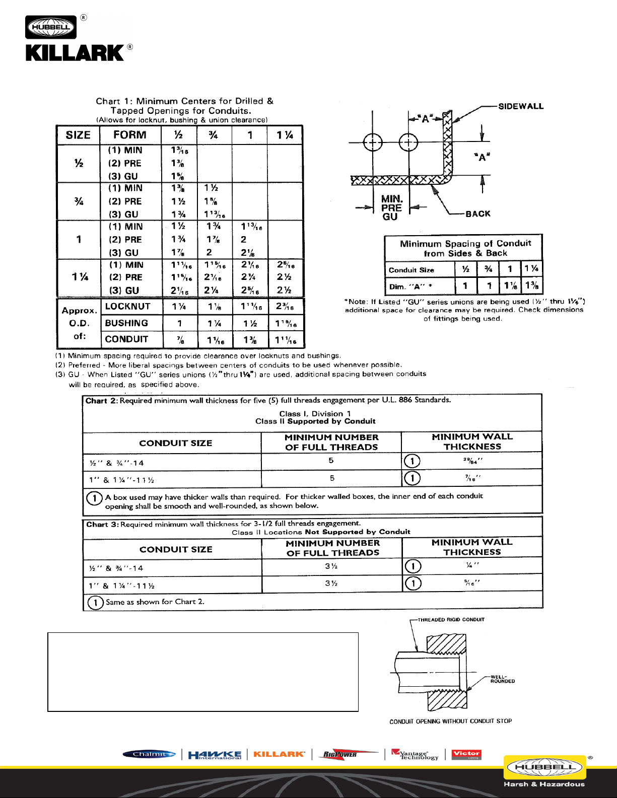
openings meet the specifications of Chart 1 below.
NOTE – Drilling and tapping of holes for mounting brackets on the casted “shelf” does not affect the flange (flamepath). Holes may
be machined at any location on the “shelf” – see inset at right:
Use caution when drilling and tapping to avoid damage to the flanged surfaces (flamepath).
(3) Wall thickness must meet the dimensions shown on Charts 2 and 3.
(4) Use Chart 1 to determine the maximum quantity and size of conduit openings permitted.
(5) 1/2 inch trade size is the minimum allowable size for any conduit opening.
(6) Refer to Table A below for maximum allowable conduit sizes.
(7) Class I, Division 1 & Class II Locations require boxes with a wall thickness sufficient to provide a minimum of five (5) full
threads (See Chart 2).
(8) Class II Locations, when the box is not supported by the conduits, requires a wall thickness sufficient to provide a minimum of
3-1/2 full threads (See Chart 3).
(9) After the size of the conduit openings has been determied for specific enclosures, measure the wall thickness and refer to the
specific Chart per the following steps :
(A) 5 Full Thread Reference Chart 2 (B) 3-1/2 Full Thread Reference Chart 3.
INSTALLATION PRECAUTIONS
(1) NEVER use hammers, screwdrivers, or any type of prying device, to open the cover. These types of tools can damage
the surface of the flanges and prevent the flamepath joint from sealing properly.
(2) Inspect flanged surfaces of the box and of the cover. Surfaces must be free of nicks, dirt or any foreign particle build-up that
would prevent a proper seal.
(3) Should the surfaces be damaged, consult the factory. Never attempt to rework the surfaces in the field. Surfaces must seat
fully against each other to provide the proper joint.
(4) Apply a light coating of Killark “LUBG” lubricant to the box flange before closing the cover. All cover screws must be installed
tightly to ensure the joint between the box and cover is sealed prior to powering the unit. An improper joint can result in an
explosion with the possibility of physical injury and property damage.
P/N 00911459 FORM NO. K1022 R8/18 ECO-3-038-18
Page 2 of 3
Page 3
HUBBELL ELECTRICAL PRODUCTS
A Division of HUBBELL INCORPORATE D (Delaware)
INSTALLATION, OPERATION &
Drilling and Tapping Instructions For Conduit Openings
NOTE:
without bottoming-out on the unthreaded area of the conduit.
3940 Dr. Martin Luther King Drive
St. Louis, Missouri 63113 USA
MAINTENANCE DATA SHEET
SERIES SWBC EMPTY ENCLOSURES
For Use In Hazardous Locations
1. Conduit openings must be tapped to a depth which allows the
conduit to be fully engaged. Recommended gaging is 1 to 2 turns
deep beyond gage mark.
2. Do not over-tap cond ui t openings: the conduit must tighten fully
P/N 00911459 FORM NO. K1022 R8/18 ECO-3-038-18
Page 3 of 3
 Loading...