

Page 1

POUR UTILISATION AVEC LES PRISES DE
120 V ET SNAPConnectMD SEULEMENT
MODE D’EMPLOI
• Pour vérifier l’état d’un circuit et d’un disjoncteur différentiel de fuite à
la terre (DDFT), mettre le commutateur à glissière (Fig. 1 et 2) à
gauche et brancher le vérificateur sur la prise. Comparer les témoins
lumineux avec le tableau imprimé sur le vérificateur (Tableau 1).
• Pour vérifier l’état des bornes d’une prise SNAPConnectMD, mettre le
commutateur à glissière (Fig. 1 et 2) à droite et introduire la borne de la
prise SNAPConnectMD
• Tous les appareils ou matériels raccordés au circuit à vérifier
doivent être débranchés afin d’éviter les erreurs de lecture.
• Le vérificateur n’est pas un instrument de diagnostic complet mais un
simple appareil servant à détecter presque toutes les conditions de
câblage non conformes.
• Soumettre tout problème identifié à un électricien qualifié.
• Le vérificateur n’indiquera pas la qualité de la mise à la terre.
• Le vérificateur ne détectera pas 2 fils vivants dans un circuit.
• Le vérificateur ne détectera pas une combinaison de défaillances.
• Le vérificateur n’indiquera pas l’inversion des conducteurs mis à la
terre et de mise à la terre.
MODE D’EMPLOI DU VÉRIFICATEUR DE DDFT
• Consulter les directives de montage du fabricant du DDFT pour
déterminer si l’appareil est installé conformément à ses spécifications.
• Vérifier si le câblage de la prise et de toutes les prises raccordée à
distance au circuit de dérivation est conforme.
• Actionner le bouton d’essai du DDFT raccordé au circuit. Le DDFT
doit se déclencher. Si ce n’est pas le cas, ne pas utiliser le circuit -
consulter un électricien. Lorsque le DDFT se déclenche, réarmer celuici. Puis, introduire le vérificateur de DDFT dans la prise à vérifier.
• Actionner le bouton d’essai du vérificateur de DDFT pendant au
moins 6 secondes pour vérifier l’état du DDFT. L’indicateur visuel du
vérificateur de DDFT doit s'éteindre une fois celui-ci déclenché.
• Lorsque le vérificateur ne fait pas déclencher le DDFT, cela suppose:
1) Un problème de câblage au niveau d’un DDFT totalement
fonctionnel ou,
2) Un câblage adéquat mais un DDFT défectueux.
Consulter un électricien pour vérifier l’état du câblage et du DDFT.
• ATTENTION - Lorsqu’on vérifie un DDFT installé dans un réseau
bifilaire (absence d'un fil de mise à la terre), le vérificateur peut fournir
une indication erronée et signaler que le DDFT ne fonctionne pas
correctement. Dans un tel cas, vérifier à nouveau le fonctionnement du
DDFT en se servant des boutons d’essai et de réarmement. Le bouton
d’essai du DDFT confirmera le bon fonctionneme.
FOR USE ON 120V RECEPTACLES AND SNAPConnect®
RECEPTACLE WIRING TERMINAL ONLY
GENERAL OPERATING INSTRUCTIONS
• To test circuit and GFCI condition, move Slide Switch (Fig. 1 & 2) to
the left and insert tester into receptacle. Compare indicator lights to
the chart(Table 1) printed on the tester.
• To test the SNAPConnect® receptacle wiring terminal condition,
move Slide Switch (Fig. 1 & 2) to the right and insert SNAPConnect®
receptacle wiring terminal into provided slot on tester. Compare
indicator lights to the chart printed on the tester (Fig. 2).
• All appliances or equipment on the circuit being tested should be
unplugged to help avoid erroneous readings.
• Tester is not a comprehensive diagnostic instrument but a simple
instrument to detect nearly all probable common improper wiring
conditions.
• Refer all indicated problems to a qualified electrician.
• Tester will not indicate quality of ground.
• Tester will not detect 2 hot wires in circuit.
• Tester will not detect a combination of defects.
• Tester will not indicate reversal of grounded and grounding
conductors.
GFCI TESTER INSTRUCTIONS
• Consult the GFCI manufacturer’s installation instructions to
determine that the GFCI is installed in accordance with the
manufacturer’s specifications.
• Check for correct wiring of receptacle and all remotely connected
receptacles on the branch circuit.
• Operate the test button on the GFCI installed in the circuit.
The GFCI must trip. If it does not – do not use the circuit – consult an
electrician. If the GFCI does trip, reset the GFCI.
Then, insert the GFCI tester into the receptacle to be tested.
• Activate the test button on the GFCI tester for a minimum of 6
seconds when testing the GFCI condition. The visible indication on
the GFCI tester must cease when tripped.
• If the tester fails to trip the GFCI, it suggests:
1) A wiring problem with a totally operable GFCI, or
2) Proper wiring with a faulty GFCI.
Consult with an electrician to check the condition of the wiring and
GFCI.
• CAUTION: When testing GFCIs installed in 2-wire systems (no
ground wire available), the tester may give a false indication that the
GFCI is not functioning properly. If this occurs, recheck the operation
of the GFCI using the test and reset buttons. The GFCI button test
function will demonstrate proper operation.
SNAPConnect® Circuit Tester
Hubbell Cat. No. SNAPCTG
Operating Instructions
Vérificateur de circuit SNAPConnectMD
Hubbell Nº cat. SNAPCTG
Mode d’emploi
Probador de circuitos SNAPConnectMD
Hubbell Cat. No. SNAPCTG
Instrucciones de operación
PARA USO EN RECEPTÁCULOS DE 120V y
SNAPConnect® CABLES TERMINALES ÚNICAMENTE
INSTRUCCIONES GENERALES DE OPERACIÓN
• Para la prueba de estado del circuito y GFCI, mover el interruptor
deslizante (Fig.1 & 2) a la izquierda e introducir el probador en el
receptáculo. Comparar los indicadores con la tabla (Tabla 1) impresa
en el probador.
• Para probar la condición de los cables terminales del receptáculo,
mueva el interruptor deslizante (Fig. 1 y 2) a la derecha y inserte la
terminal de cableado del receptáculo SNAPConnect® en la ranura
proporcionada en el probador. Comparar el indicador luminoso al
gráfico impreso en el medidor (Fig. 2).
• Todos aparatos o equipos conectados en el circuito de prueba deben
estar desconectados para evitar lecturas erróneas.
• El probador no es un instrumento de diagnóstico integral sino un
instrumento simple para detectar casi todas fallas comunes de los
cableados. Refiera todos los problemas indicados a un electricista
calificado.
• El probador no indica calidad de tierra.
• El probador no detectará 2 hilos de fase en el circuito.
• El probador no detectará una combinación de defectos.
• El probador no indican inversión de tierra y de puesta a tierra de los
conductores
INSTRUCCIONES DEL PROBADOR GFCI
• Consultar las instrucciones del fabricante del GFCI para determinar
que el GFCI está instalado de acuerdo con las especificaciones del
fabricante.
• Compruebe el correcto cableado del receptáculo y todos los
receptáculos conectados en forma remota en el circuito derivado.
• El ICFT (GFCI) debe funcionar. Si no lo hace – no use el circuito –
consulte un electricista. Si el ICFT (GFCI) funciona, oprima el botón de
RESET del ICFT (GFCI).
Entonces, introducir el probador de ICFT (GFCI) en el receptáculo a
ser probado
• Activar el botón de prueba en e l probador ICF T ( GFCI) por un
mínimo de 6 segundos cuando se prueba la condición del ICFT
(GFCI). El indicador visible en el probador ICFT (GFCI) debe cesar
cuando se ha disparado.
• Si el probador no dispara el GFCI, se sugiere esto:
1) Problema de cableado con un GFCI totalmente operable, o
2) Cableado correcto con un GFCI defectuoso.
Consultar con un electricista que compruebe el estado del
cableado y el ICFT (GFCI).
• PRECAUCIÓN: Cuando se prueba el ICFT (GFCI) instalado en un
sistema de 2 hilos (sin cable de tierra disponible), el probador puede
dar una indicación falsa de que el GFCI no está funcionando
apropiadamente. Si esto ocurre, vuelva a verificar la operación del
ICFT (GFCI) con los botones de prueba. Los botones de prueba del
English
Español
Français
Page 2
LED INDICATOR
INDICA TEUR DEL
INDICADORA DE LED
LABEL
ÉTIQUETTE
ETIQUETA
CONDITION
ÉTAT
CONDICIÓN
ORANGE
NARANJA
OPEN GROUND
MALT OUVERTE
TIERRA ABIERTO
GROUND CONTACT IS NOT CONNECTED
CONTACT MALT NON CONNECTÉ
CONTACTO TIERRA NO CONECTADO
ORANGE
NARANJA
OPEN NEUTRAL
NEUTRE OUVERTE
NEUTRAL ABIERTO
NEUTRAL CONTACT IS NOT CONNECTED
CONTACT NEUTRE NON CONNECTÉ
CONTACTO NEUTRAL NO CONECTADO
OPEN HOT
VIVANT OUVERT
CALIENTE ABIERTO
HOT CONTACT IS NOT CONTACTED
CONTACT VIVANT NON CONNECTÉ
CONTACTO CALIENTE NO CONECTADO
ORANGE
NARANJA
RED
ROUGE
ROJO
REVERSED HOT/GROUND
INVERSION VIVANT/MALT
INVERTIDO CALIENTE/TIERRA
HOT AND GROUND CONNECTIONS REVERSED
CONNEXIONS VIVANT ET MALT INVERÉES
INVERTIDO CONEXIÓNES CALIENTE Y TIERRA
RED
ROUGE
ROJO
ORANGE
NARANJA
REVERSED HOT/NEUTRAL
INVERSION VIVANT/NEUTRE
INVERTIDO CALIENTE/NEUTRAL
HOT AND NEUTRAL CONNECTIONS REVERSED
CONNEXIONS VIVANT ET NEUTRE INVERÉES
INVERTIDO CONEXIÓNES CALIENTE Y NEUTRAL
ORANGE
NARANJA
ORANGE
NARANJA
CORRECT
CORRECTO
ALL CONNECTIONS ARE CORRECT
TOUTES LES CONNEXIONS CORRECTES
TODOS LOS CONEXIONES SON CORRECTOS
HUBBELL DE MEXICO garantiza este producto, de estar libre de defectos en materiales y mano
de obra por un período de un año a partir de la fecha de su compra. HUBBELL reparará o
reemplazará a su juicio el producto en un plazo de 60 días. Esta garantía no cubre desgastes
por uso normal o daños ocasionados por accidente, mal uso, abuso o negligencia. El
vendedor no otorga otras garantías salvo lo expresado arriba y excluye expresamente daños
incidentales o consecuenciales. ESTA GARANTÍA ES VÁLIDA SÓLO EN MÉXICO.
HUBBELL
DE
MÉXlCO, S.A.
DE
C.V.
Av. Insurgentes Sur # 1228 Piso 8, Col. Tlacoquemecatl del
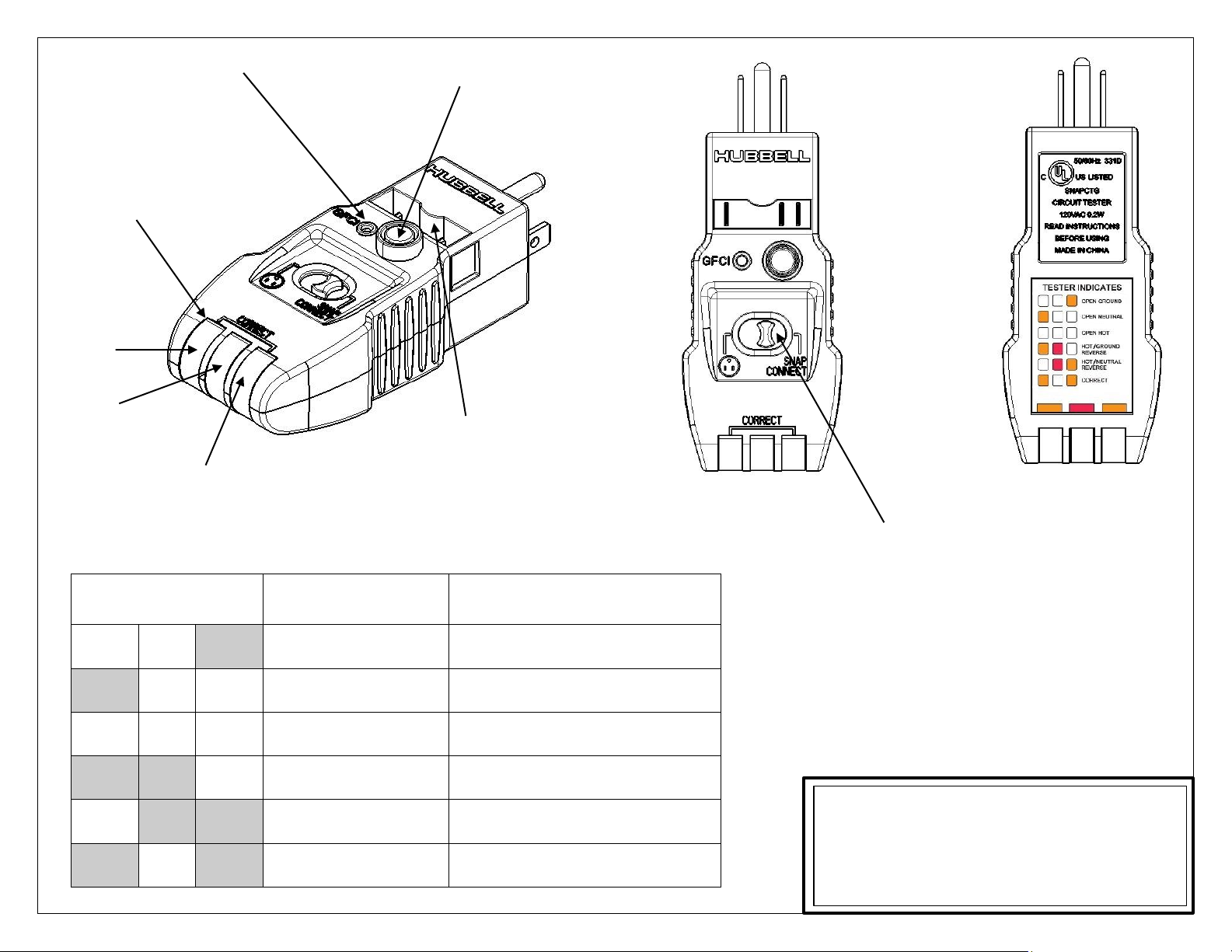
GFCI INDICATOR LIGHT
VOYANT DU DDFT
GFCI TEST BUTTON
BOUTON D'ESSAI DU DDFT
BOTÓN INDICADORA DE ICFT
INDICATOR LIGHTS
TÉMOINS LUMINEUX
LUCES INDICADORA
ORANGE
NARANJA
RED
ROUGE
ROJO
ORANGE
NARANJA
SNAPCONNECT INSERT SLOT
FENTE D’INSERTION DU SNAPCONNECT
ESPACIO DE INSERCIÓN DE SNAPCONNECT
FIG. 1
FIG. 2
FIG. 3
RECEPTACLE & SNAPCONNECT SWITCH
COMMUTATEUR À GLISSIÈRE POUR PRISE ET SNAPCONNECT
INTERRUPTOR DE RECEPTÁCULOS Y SNAPCONNECT
TABLE 1: CIRCUIT CONDITION INDICATOR CHART / TABLEAU 1: INDICATION DE L’ETAT DU CIRCUIT /
TABLA 1: CIRCUITO DE INDICADOR DE ESTADO
 Loading...